Boeing-747 _ Final_Project of Boeing
MODELLING AND ASSEMBLY OF BOEING 747-8 USING SOLIDWORKS
OBJECTIVE:
To set up the blueprints for Boeing 747-8.
To model the individual parts of the Boeing 747-8 using SolidWorks.
To assemble all the parts with proper mates.
To give proper appearances and decals for the parts.
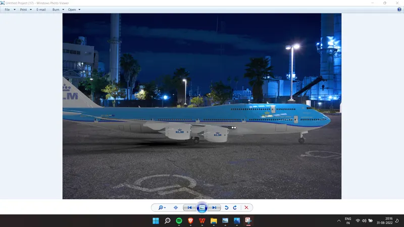
To position the assembly and set up cameras, lights and environments.
To create photorealistic renders using SolidWorks Visualize.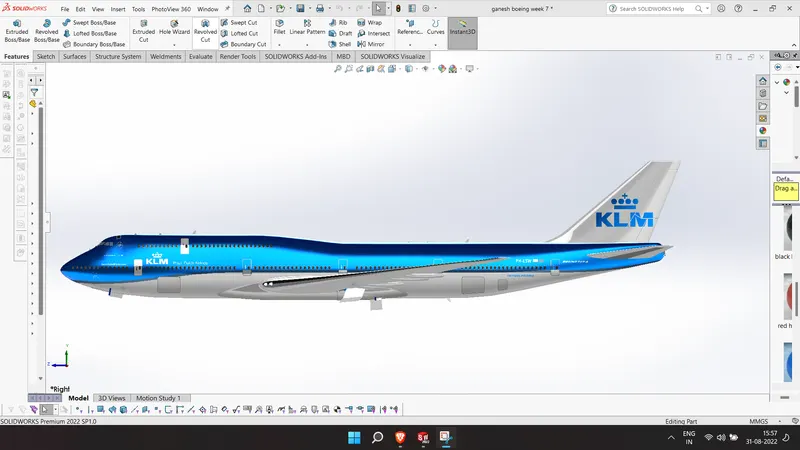
INTRODUCTION:
SolidWorks is a 3D CAD and CAE software developed by Dassault Systèmes. It provides dedicated tools and workflows that streamline the design and development of products. It is used for sketching, part modelling, sheet metal design, simulation, mold design, and other computer-aided manufacturing processes.
SolidWorks Visualize is a software used to create photorealistic or non-photorealistic renders. It is also used for post-processing images and even creating basic presentation animations.
Boeing 747-8 is the largest variant of the Boeing 747 range of wide-body jet airliners developed by Boeing Commerical Airplanes. This variant has been initially launched on November 14, 2005 and it began commercial service in June 2012. It was designed to compete against the Airbus's Airbus A3XX.
DESIGN METHODOLOGY
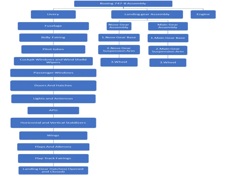
Given sketches for the design purpose. We want insert these sketches into a design software we were using. By using command key called sketch tool. With the help of teaching staff and with the given dimensions we have to create the sketches that are need to develop the Boeing aircraft.
Fuselage: I used to create fuselage with the given dimensions and with the given sketches as shown in the . Fuselage is the main body of the aircraft that will used for arrangement of the seats where the people should seated and fuselage is also used for carrying cargo. Sometimes it is used to carry fuels.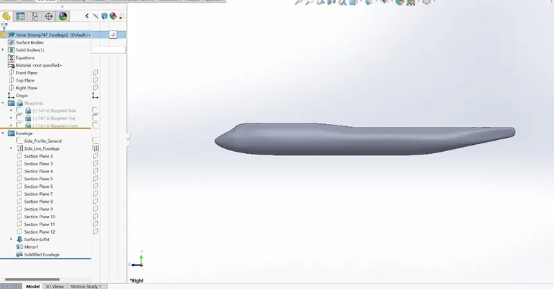
Belly fairings: I have created this part using fuselage body with a given dimensions. The belly fairing is used as support for body landing gear as well as wing . the belly fairing which is attached to the fuselage.
Nose cone: After belly fairing the nose cone part is created using the dimensions given in the video using previously created sketch. Nose cone located at front of the aircraft. Nose cone is created using the strips it is used as the insulators. It is used protect weather radar from aerodynamics forces. Conducted strips are used to protect from lighting strikes.
Pitot tubes: Pitot tubes is created using fuselage sketch with a given dimensions for design. 4 Pitot tubes are created for given aircraft. Pitot tube is also known as Pitot probe is a device used for flow measurement used to measure floe velocity. Determine the airspeed of the aircraft. Measure the liquid, air, gas velocity in certain industries. Pitot tube is used measure the local floe velocity at any given point at flow stream.
Cockpit windows: This sketch is created with a given dimensions and given sketches as shown in the Fig1. Cockpit windows are created on the fuselage. The cockpit windows I have created for this Boeing aircraft the weight will be 68kgs and thickness will be 76mm.
Windshield wipers: This sketch is created with the given dimensions using the previous sketch. It is used potentially for ground offs, take offs, landings. They have different speed setting as same as car. 2 wipers are created for given aircraft one on the pilot side and other on co-pilot side.
Passenger windows: The passenger windows are created separately using sketch block, and insert the sketch block into the main sketch, and using projected lines project the windows on to the fuselage and add appearance. I have created 250 windows for the aircraft.
Doors: This sketch is created using sketch block with a given dimensions and inserted into the main sketch. Using spilt lines spilt on to fuselage and add appearance for the created doors. I created 6 doors on each sides for a given aircraft.
Hatches: This sketch is created using the given dimensions and sketches as shown in the Fig1. Using spilt lines spilt on to the fuselage and appearance.
Lights and antennas: This sketch is created on the top of the fuselage using the given dimensions in the video. 2 lights at the front top of the fuselage and 3 wing shaped antennas using the command called move and copy with the dimensions given. 2 slot shaped antennas with the given dimensions.
Auxiliary power unit: This sketch is created using dimensions given in the video on tail of the aircraft. APU is a device at backside of the aircraft used to provide power for other functions. Tail light is created below the APU at the end of the aircraft.
Vertical stabilizer: This sketch is created at the tail of the aircraft vertically with a given dimensions. Using lofted surface command loft the sketch created. It is used control the directional stability of the aircraft. Static Discharges points are used to discharges things such as lightning.
Horizontal stabilizer: This sketch is created at the tail of the aircraft horizontally with a given dimensions. Using projected curves project the lines, create a lofted surface using loft command and add appearance.
Wings: This sketch is done using the sketches as shown in the Fig1, with a given dimensions, and using previous sketch done. After creating project the created sketch using projected curve command. Wing is the main part of the aircraft which is used produce lift by separating the flow. 2 wings are created on the aircraft one is on left side and other is on right side.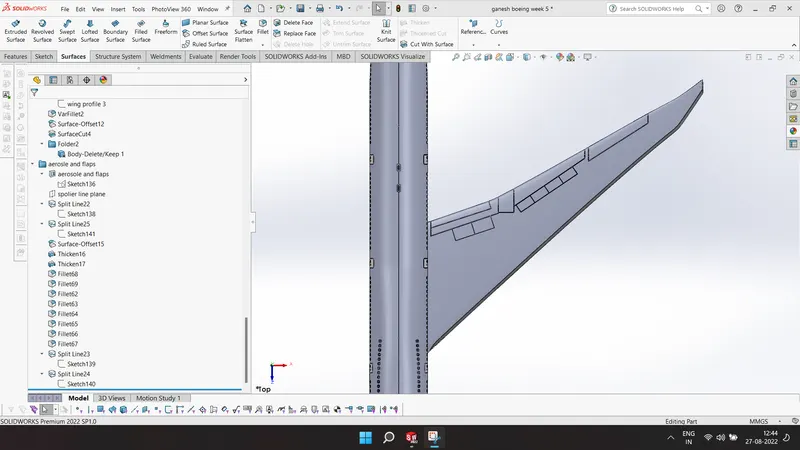
Flaps and Ailerons: This sketch is created using the sketches as shown in the Fig1, with a given dimensions and this sketch will done on the wing trailing edge of the aircraft. Ailerons are used when aircraft acts for roll moment. Flaps are used as high lift devices.
Flap tracing's: Flap tracking’s are created below the wing, which are used for support of the flaps when they are moving up and down.
Landing gea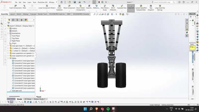 r axis: This sketch created by creating the points on the landing gear provided on the sketches shown in the Fig1, with the given dimensions. Landing gear axis are used for the assembly purpose to assembled landing gears of the aircraft.
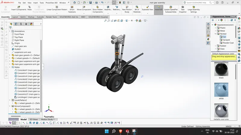
Landing gear: This sketch is created separately using new part with a given dimensions. It is a step by step process first we want to create a wheel, main support, suspension arm. At last we want to do assembly using a created parts with assembly command. Landing gears are used when the aircraft take off ,landing, and ground roll. We want to 1 nose landing gear, 4 main landing gears.
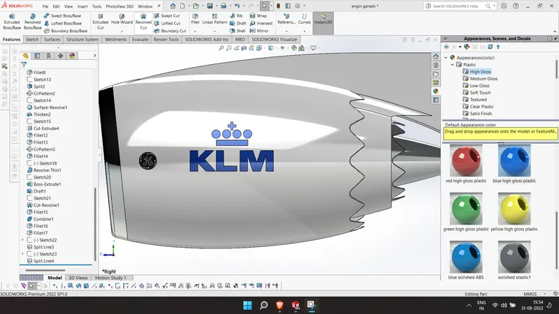
Engine: This part is created using the sketch as shown in the and with the given dimensions. Engine is the main part of the aircraft used to produce a thrust to move aircraft forward.
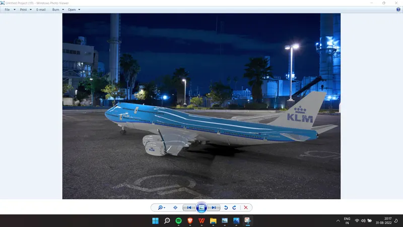
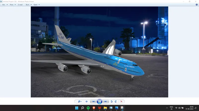
Livery: Livery in the sense adding the names on the aircraft which is given through company or airline.
Assembly: After creating all the parts of the aircraft now we need to assembled the separately created parts. To create a perfect aircraft. I have assembled all parts using assembly command with a given dimensions.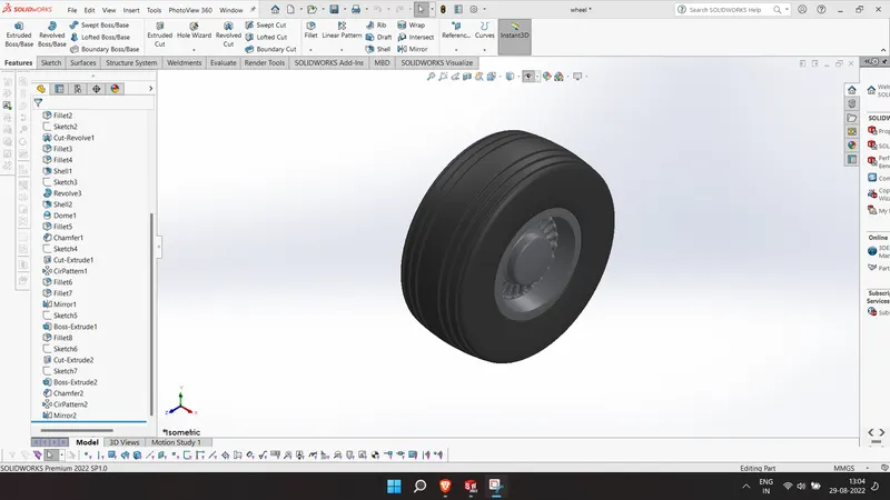
TOOLS
Right, top, front planes: These are the planes used for creating sketches.
Insert command: It is a type of command used to insert a sketch picture into sketching plane. To insert a block and to insert other commands like surfaces, curve, faces.
Line: This command is used to draw line, curve etc.
Spline: This command is to create splines on the sketches. We can drawn into any shape that we required.
Rectangle: This command is used draw rectangle at required sketch.
Circle: This command is used to draw a circle in the sketch to required diameter.
Point: This command is used keep the point for the reference of the sketch.
Offset: This command is used for offset the drawn sketch to the given dimension. Offset means to create a new sketch to the created sketch.
Smart dimensions: This command is used to define the dimensions of the sketch. The all dimensions are defined in mm(millimeters).
Convert entities: This command is used to convert the entities of created sketch to create a new sketch.
Mirror entities: This command is used to mirror the entities like( lines, splines etc.) of the sketch created to one side to other side by creating the construction line.
Spilt lines: This command is used to spilt the created sketch on required side. This can be done selecting the created sketch and the face to be spilt.
Project curves: This command is used to project the curves of the selected sketch. This is used to create two curves into a single curve.
Planes: This planes are created by using the reference command. The planes are created to create a new sketches on that plane.
Axis: This command is used to create the reference for the sketch.
3.1 FEATURES
Extrude boss base: This command is used to create a extrude of an created sketch to given dimensions. This is a command used convert 2D sketch to 3D sketch.
Resolved Boss Base: This command is to resolve or create a circular path of an created sketch to the given dimensions. This command can be created using degrees ( 1800 , 3600).
Lofted boss: This command used to create the loft of the created sketch. This command can be done by selecting point to create a loft and reference lines.
Extruded cut: This command is used cut 3D sketches created to the given dimensions. It can be cut 3D the parts using commands based on the cut.
Shell: This command is used cut 3D part of the created sketches.
Mirror: This command is used to create the mirror of the faces , bodies using the planes as a reference like(right, front, top).
CONCLUSION
At last I have concluded that I have experienced the designing of the Boeing-747 aircraft. And I have experienced to use solid works software that I haven’t learnt in my course. Now I have interested in working designing course.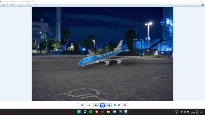
- Ritik Sonkamblehello brother can you contact me on LinkedIn https://www.linkedin.com/in/ritiksonkamble2000.