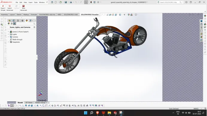
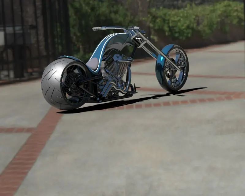
Photo Realistic Rendering
DESIGNE ,ASSEMBLY AND RENDERING OF
AMERICAN CHOPPPER USING SOLID WORKS
OBJECTIVE:
To model an American chopper bike using and to create some rendered images of the same.
INTRODUCTION:
This project report is about how I created an American chopper after modelling it's components and assembling it using Solid works.Here I will briefly explain how I did this project using solid works.
METHODOLGY
PLAN OF ACTION FOR DESIGNING CHOPPER:
- Modelling various components/parts
- Assembly of components/parts
- Setting up camera, environment, lights etc
- Final rendering
Various commands and features I used to model the parts are as follows;
2D sketch : A 2D sketch is the base to create a 3D model. It is created on plane on 2 axes. Various line tools, circles, rectangles, splines etc are mainly used to create sketches. Tools such as 'Power trim', 'Trim extend' etc. were widely used in this project.
Projected curves : Used to project a sketched curve on to a model face to create a 3D curve. It can be also created by creating sketches on two intersecting planes.
Trim : Used to remove the extra edges of intersecting lines on a 2D sketch.
Offset : Used to add sketch entities by offsetting faces, edges, curves etc to a specified direction and distance.
Convert entities : Convert selected model edges or sketch entities into current sketching plane.
Boss Extrude : It is used to extrude a sketch or selected contours in specified directions thus creating a solid feature.
Revolved Boss : Revolves a sketch or selected sketch contours about an axis, thus forming solid feature
Swept Boss : Sweeps a closed profile along an open or closed path to create a solid feature.
Extruded Cut : It removes material from a 3D model according to the selected profile along specified direction.
Revolved Cut : It removes material from a 3D model according to the selected profile about a specified axis.
Loft : The loft feature helps to create shapes by making transition between multiple profiles and make use of guide curves to form complex geometry.
Dome : A dome is a smooth rounded vault forming the outside face of a body or structure.
Fillet : used to connect adjacent faces with a specified tangent curve.
Chamfer : Used to connect adjacent faces with a specified inclined line.
Combine : It is used to combine two or more solid bodies together.
Extended surface : Used to extend the selected edge of a surface along a specified direction and distance.
Ruled surface : It is used to insert a ruled surface according to the selected edges.
Offset surface : Creates offseted surface using one or more faces.
Surface fill : Create a surface patch within a selected boundary.
Boundary surface : Creates a boundary surface between profiles in two directions.
Lofted surface : It is used to create lofted surface between two more profiles.
Trim surface : It is used to remove the unwanted portion of a surface according to a sketch profile or other features.
Shells : Used to hollows out a part, leaves open the faces we select and creates thin walled features on the remaining faces.
Assemblies : Used to build complex assemblies consisting of many components which can be parts or other assemblies called sub assemblies.
- Modelling various components/parts
This American chopper bike consists of 13 parts;
- Transmission Belt
- Kick stand
- Chain
- Rear Fender
- Rear Wheel
- Front Wheel
- Front Fender
- Pedal
- Oil Tank
- Front Fork
- Chassis
- Engine
- Gas Tank
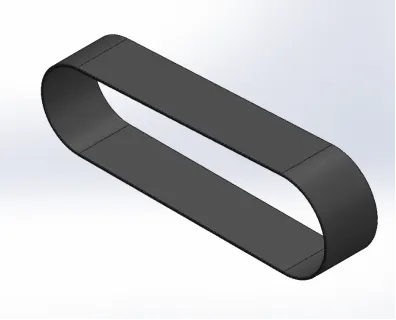
TRANSMISSION BELT
Commands used:
2D sketch
Fillet
Smart Dimensions
Appearance
Extruded boss/base
Image of the model part:
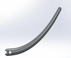
KICK-STAND
Commands used:
2D sketch
Fillet
Smart Dimensions
Appearance
Split
Lofted boss/base
Extruded boss/base
Extrude cut
Dome
Image of the model part:
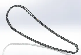
Chain
Commands used:
2D sketch
Fillet
Smart Dimensions
Appearance
Extruded boss/base
Curve driven pattern
Mirror feature
Body-Delete/keep
Image of the model part:
REAR FENDER
Commands used:
2D sketch
Fillet
Smart Dimensions
Appearance and decals
Split
Revolve
Shell
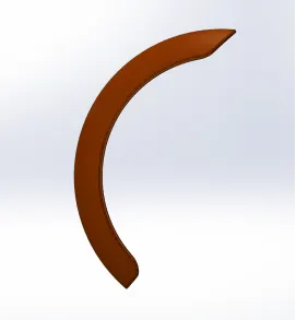
Image of the model part:
REAR WHEEL
Commands used:
2D sketch
Offset entities
Fillet
Trim entities
Smart Dimension
Appearance
Chamfer
Mirror Entities
Combine
Extruded cut
Revolved cut
Circular pattern
Extruded boss/base
Revolved boss/base.
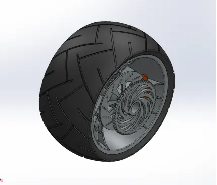
Image of the model part:
FRONT FENDER
Commands used:
2D sketch
Fillet
Smart Dimensions
Appearance
Split
Revolve
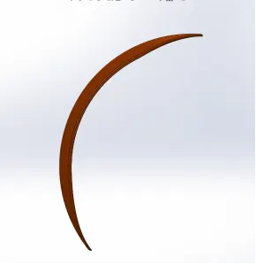
Image of the model part:
FRONT WHEEL
Commands used:
2D sketch
Offset entities
Fillet
Trim entities
Smart Dimensions
Appearance
Chamfer
Mirror Entities
Extruded cut
Revolved cut
Combine
Circular pattern
Extruded boss/base
Image of the model part:

PEDAL
Commands used:
2D sketch
Fillet
Smart Dimensions
Appearance
Chamfer
Revolved boss/base
Extruded boss/base
Linear Pattern
Dome
Image of the modelled part:
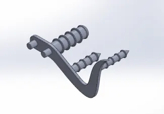
OIL TANK
Commands used:
2D sketch
Fillet
Smart Dimensions
Appearance and decals
Extruded boss/base
Combine
Shell
Image of the model part:
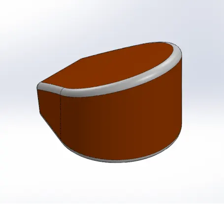
FRONT FORK
Commands used:
2D sketch
Fillet
Trim entities
Smart Dimensions
Appearance
Dome
Mirror Entities
Body-Move/Copy
Combine
Extruded cut
Revolved cut
Circular pattern
Linear pattern
Projected curve
Reference Plane
Extruded boss/base
Swept boss/base
Revolved boss/base.
Image of model part:
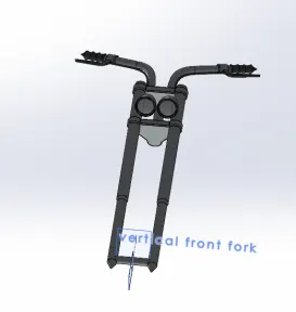
ENGINE
Commands used:
2D sketch
Sketch picture
Fillet
Trim
Smart Dimensions
Appearance
Chamfer
Mirror
Split
Combine
Dome
Extruded cut
Circular pattern
Linear pattern
Projected curve
Composite curve
Reference Plane
Extruded boss/base
Revolved boss/base
Swept boss/base.
Images of the model part:
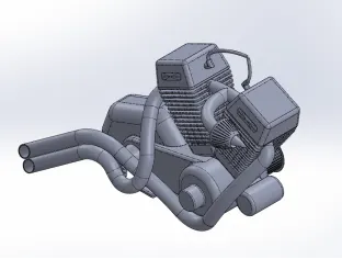
CHASSIS
Commands used:
2D sketch
Sketch picture
Fillet
Split
Smart Dimensions
Appearance
Chamfer
Mirror
Combine
Dome
Extruded cut
Projected curve
Reference Plane
Extruded boss/base
Revolved boss/base
Swept boss/base.
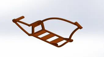
Images of the modelpart:
FUEL TANK
Commands used:
2D sketch
Sketch picture
Fillet
Trim
Smart Dimensions
Appearance and decals
Shell
Mirror
Split line
Projected curve
Reference Plane
Surface trim
Swept cut
Lofted surface
Boundary surface
Swept surface
Extruded surface
Knit surface.
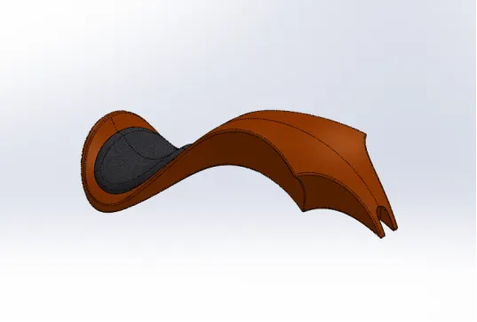
Image of model part:
Assembly of components/parts
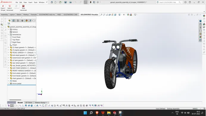
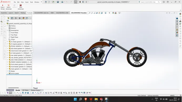
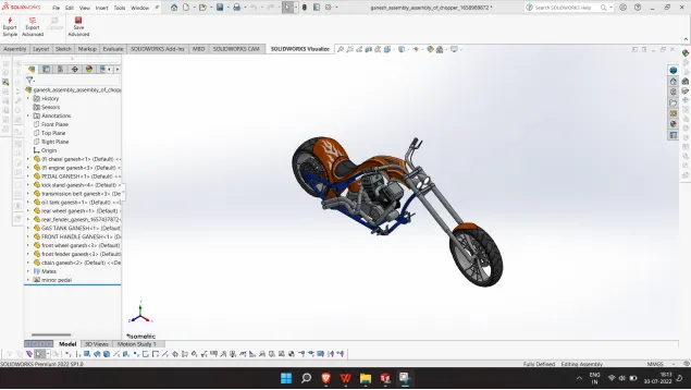
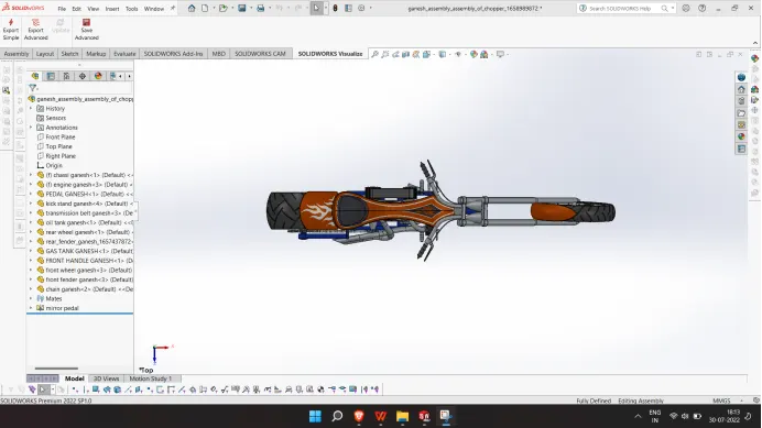
In order to assemble the parts, all the parts are inserted in assembly file one by one as per the requirement. After that required mates were applied to each and every individual component for proper alignment. In order to snap the entire motorcycle to the floor required mates were applied to kick stand and wheels with top plane. After assembling I applied some decals and did a rendering on 'Photo view 360 and solid works visualize.