Boeing-747 _ Final_Project of Boeing
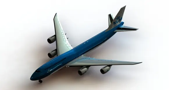
BOEING 747 DESIGN AND RENDER
Files link:https://drive.google.com/file/d/1iYOi_ZoE-_ToysN8M2NFr4MaJuTSvYdd/view?usp=sharing
Objective:
- To design and assemble each and every component of the Boeing 747
- To acquire knowledge about part design and surface design
- To understand the flow of process in designing a plane surface
- To render photo-realistic images of the Boeing 747
Introduction
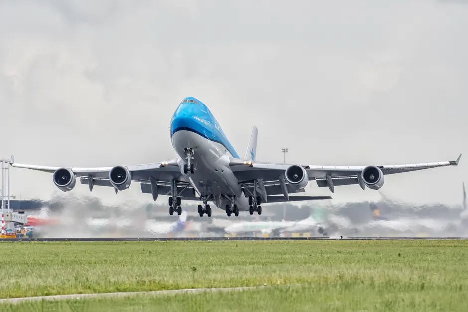
The Boeing Company is an American multinational corporation that designs, manufactures, and sells airplanes, rotorcraft, rockets, satellites, telecommunications equipment, and missiles worldwide. The Boeing 747 is a large, long-range wide-body airliner designed and manufactured by Boeing Commercial Airplanes in the United States between 1968 and 2023. The 747 is a four-engined jet aircraft, initially powered by Pratt & Whitney JT9D turbofan engines, then General Electric CF6 and Rolls-Royce RB211 engines for the original variants. With a ten-abreast economy seating, it typically accommodates 366 passengers in three travel classes
Design methodology
Features And Tools Used In The Design Process:
Solid modelling:
1) Boss Extrude
• Boss extrude is the most basic and important function in solidworks used to create a solid from a sketch
• It transforms the 2d sketch into a 3d object
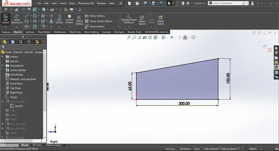
Figure 1.1 Fully defined 2d sketch
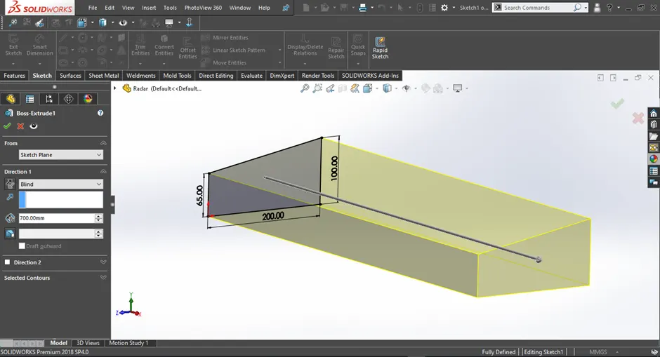
Figure 1.2 Boss Extrude feature been aplied
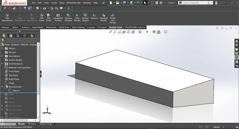
Figure 1.3 3d geomerty created from Boss Extrude
2) Cut Extrude
• Cut extrude is used to remove material from a solid or a surface
• It requires a sketch and a geometry which has to be cut
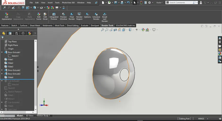
Figure 1.4 3d geomerty to be cut
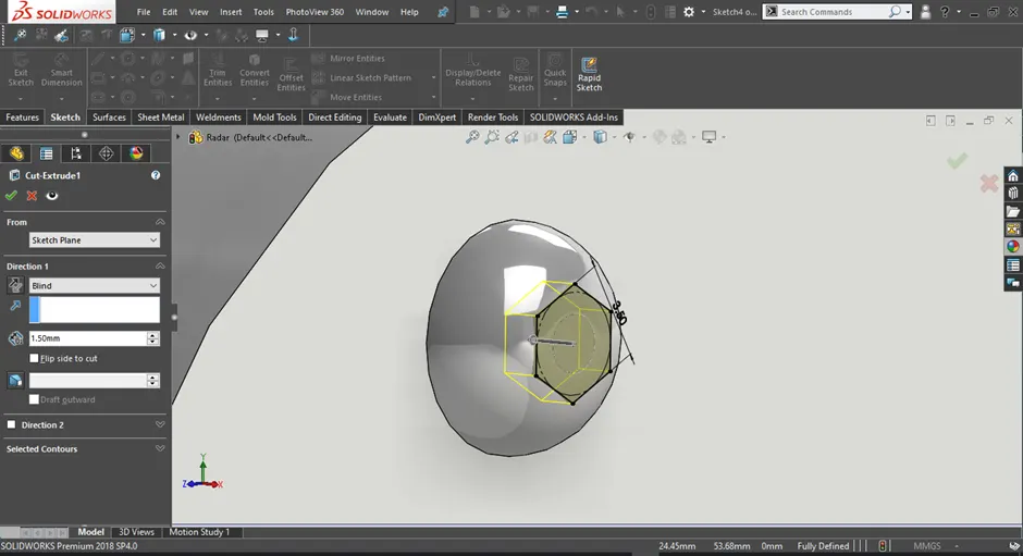
Figure 1.5 Cut Extrude feature been applied
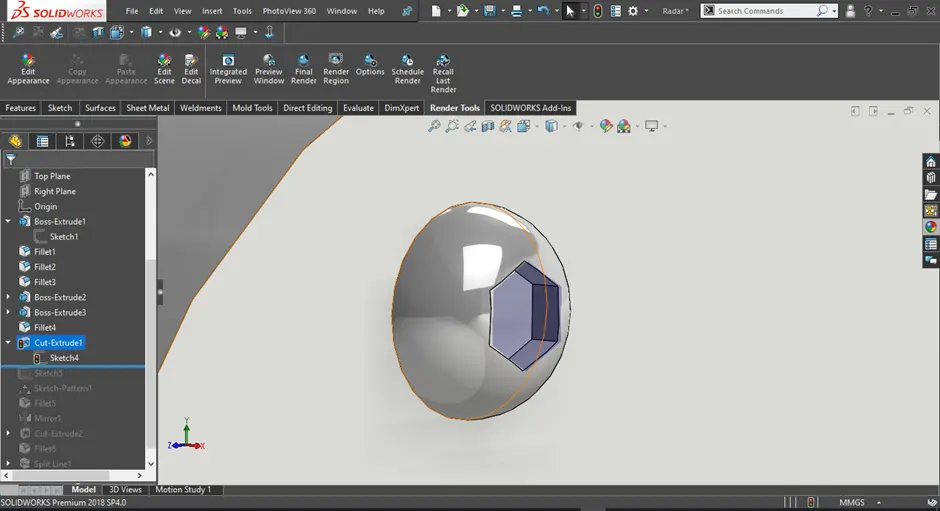
Figure 1.6 Resulting geometry from cut extrude
3) Revolve
• Revolve is used to create solid/surface by revolving a sketch around a given axis
• Based on the selection of axis the revolve shape will also change
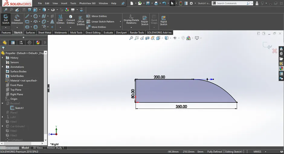
Figure 1.7 Fully defined 2d sketch
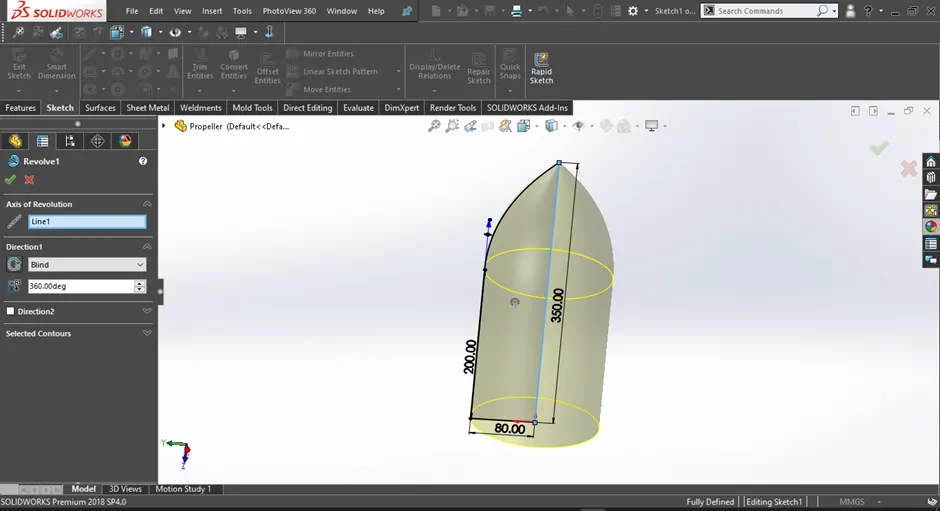
Figure 1.8 Revolve Boss/Base feature been applied
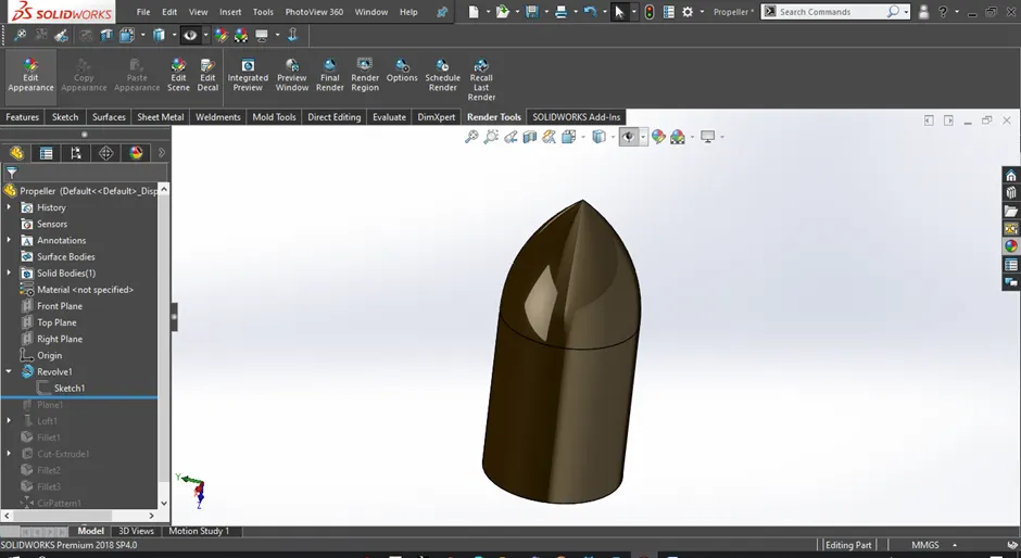
Figure 1.9 3d geomerty created from Revolve Boss/Base
4) Fillet
• Fillet feature is used to round off sharp edges od a 3d model and given it a more cleaner look
• The most commpnly used fillet options are constant size fillet and the full round fillet
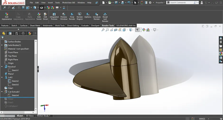
Figure 1.10 model before applying fillet
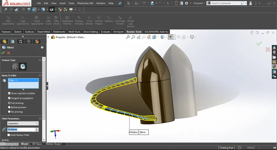
Figure 1.11 Applying fillet tto the model
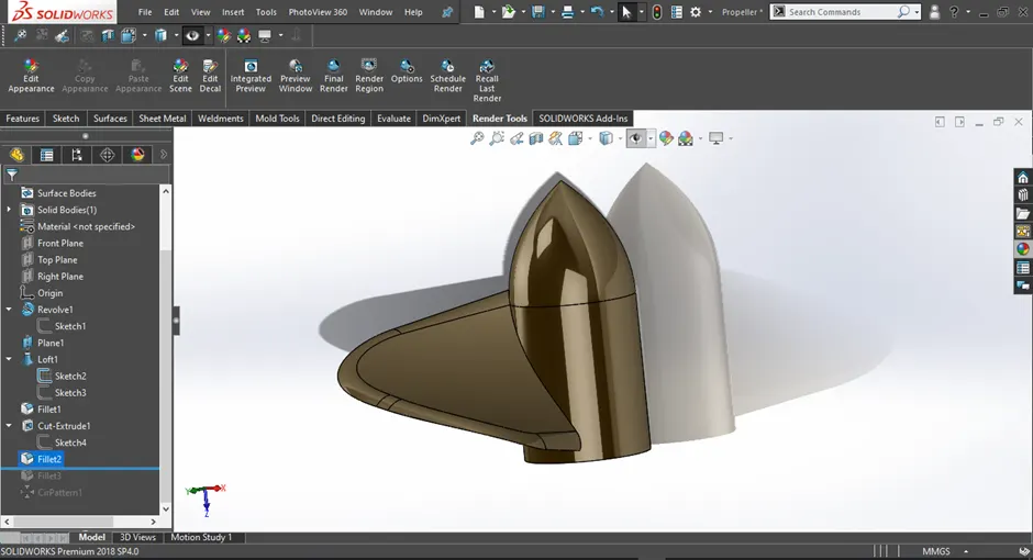
Figure 1.12 Resulting geomertry from fillet
5) Shell
• Shell command is used to make a 3d object hollow by reomving the inner geometry while maintainig a wall thickness as desired by the user
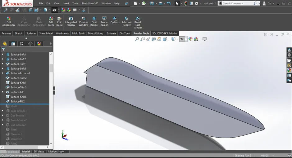
Figure 1.13 Before aplying shell feature
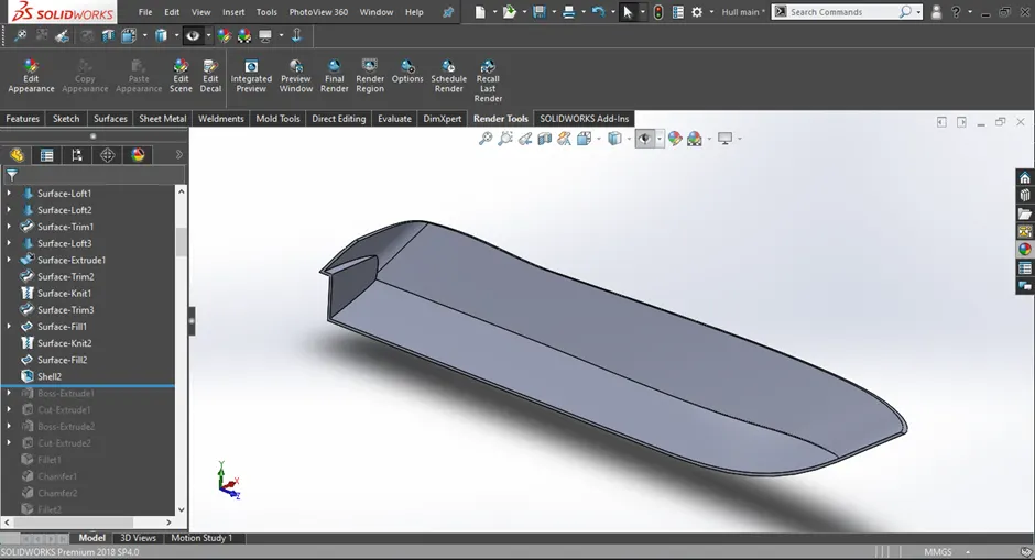
Figure 1.14 After aplying shell feature
6) Projected Curve
• Projected curves creates a 3d curve based on two 2d skethes provided by the user
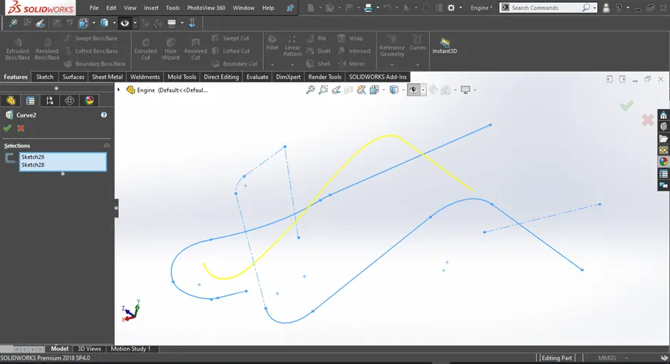
Figure 1.15 Example of projected curve
7) Mirror
• The mirror option helps duplicate a feature or a body based on a plane or a fcae slected by the user
• The user can create only half of the required geometry and the mirror it to get the required result
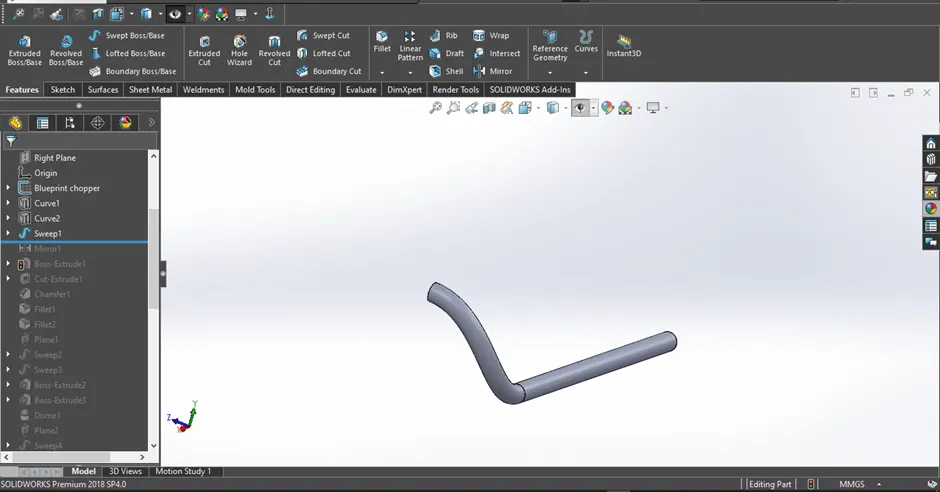
Figure 1.16 Before apllying mirror
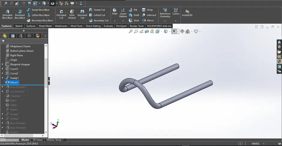
Figure 1.17 After apllying mirror
Surface modelling:
1) Surface Extrude
• Surface extrude is used to create a 3d surface from a 2d sketch(both open and closed sketches)
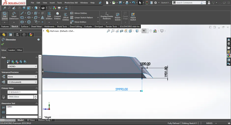
Figure 2.1 Fully defined 2d sketch
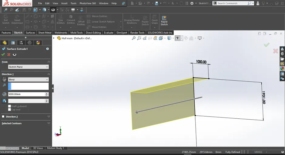
Figure 2.2 Surface Extrude feature been applied
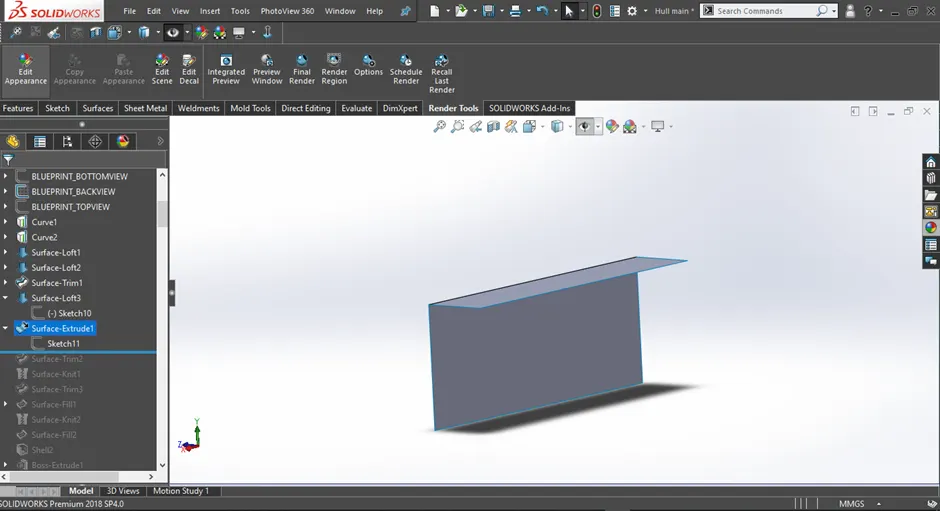
Figure 2.3 3d geomerty created from Surface Extrude
2) Surface Loft
• Surface loft is used to create a 3d sketch with the help of two or more profiles(either 2d or 3d)
• Guide curves can also be used to alter the shape of the loft and make it more defined
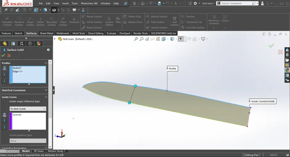
Figure 2.4 Surface loft feature been applied
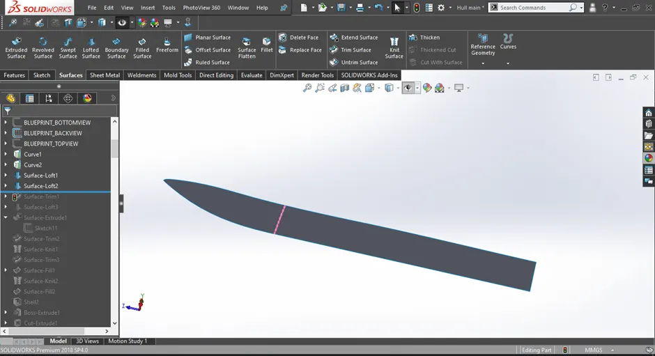
Figure 2.5 3d geomerty created from Surface loft
3) Surface sweep
• Surface sweep is used to create a 3d sketch with the help of a profile and a path
• Guide curves can also be used to alter the shape of the sweep and make it more defined
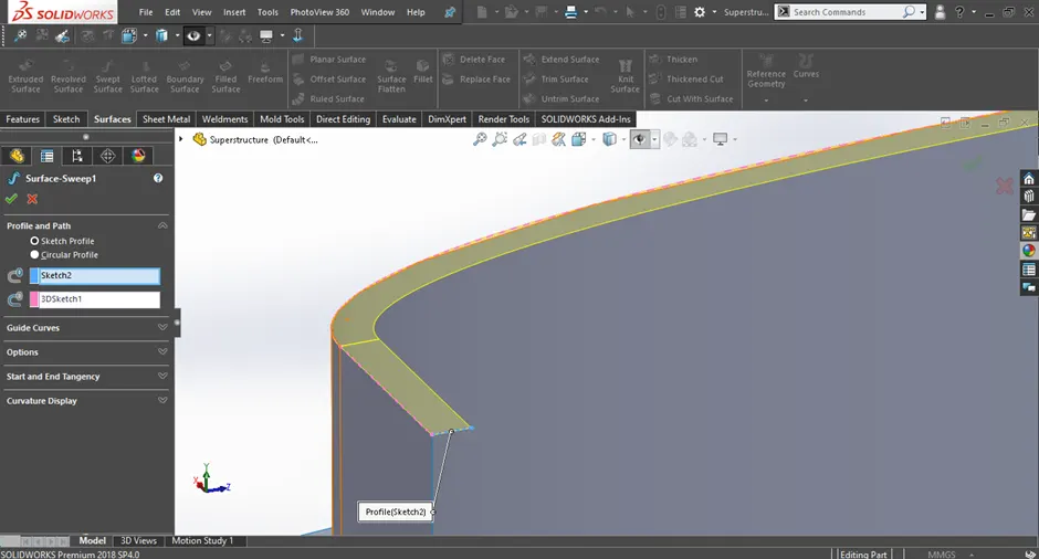
Figure 2.6 Surface sweep feature been applied
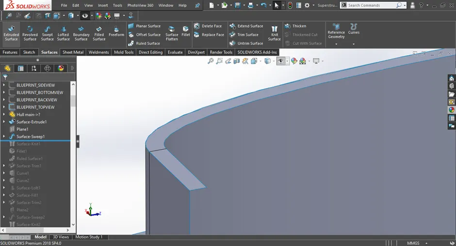
Figure 2.7 3d geomerty created from Surface sweep
4) Surface trim
• Suface trim is used to trim a section of a surafce with the help of another surface or a sketch
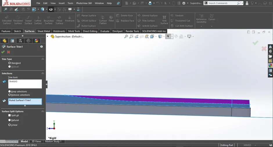
Figure 2.8 Surface trim feature been aplied
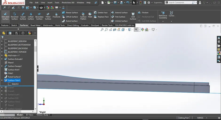
Figure 2.9 After applying Surface trim
5) Surface fill
• Surface fill is used to fill a closed boundary either with the help of sketches or surfaces
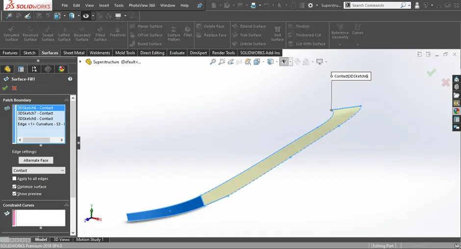
Figure 2.10 Surface fill feature been aplied
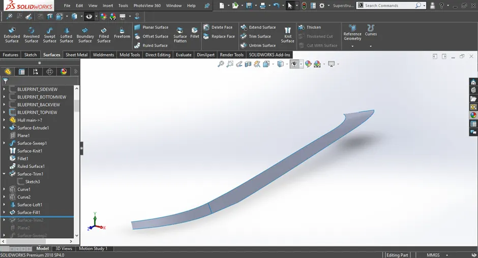
Figure 2.11 3d geomerty created from Surface fill
6) Knit surface
• Knit surface feature helps to knit the gaps exixting between the merging surfaces.
• If the surface is properly knitted then the edges will turn from blue to black as shown below
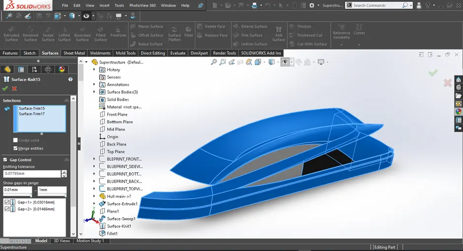
Figure 2.12 Knit surface feature been aplied
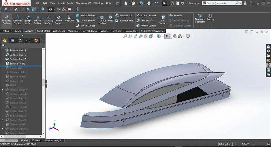
Figure 2.13 After applying Knit surafce
7) Offset surface
• Offset surface basically offsets an already existing surface to a distance required by the user
Figure 2.14 Offset surface feature been aplied
Figure 2.15 After applying offset surface
8) Thicken
• Thicken feature creates a thickened solid from an existing surface
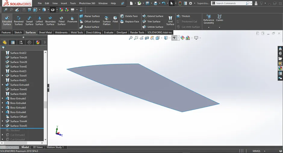
Figure 2.16 Before apllying thicken
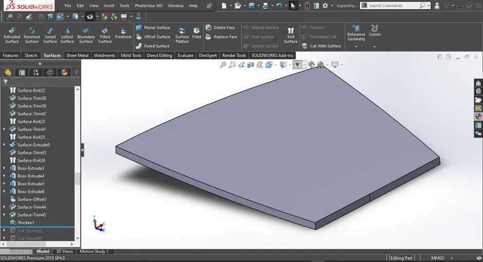
Figure 2.17 After apllying thicken
Blueprint
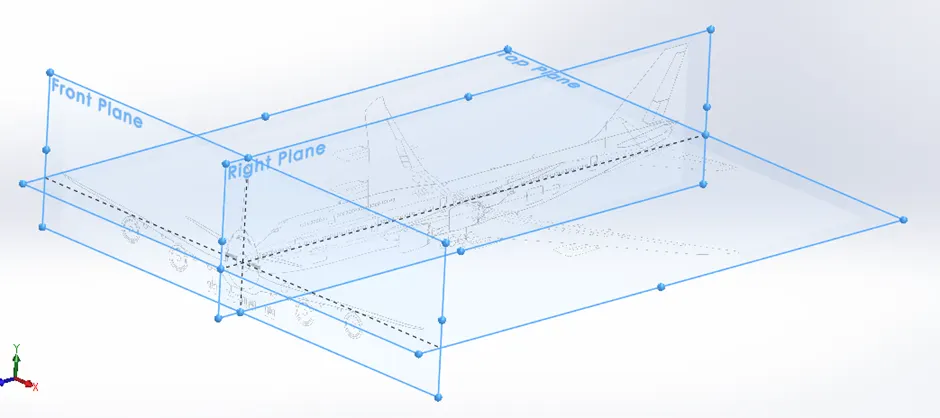
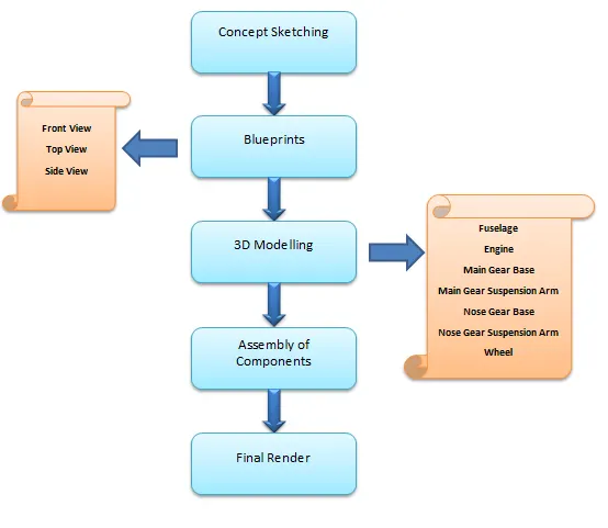
Design Of Components
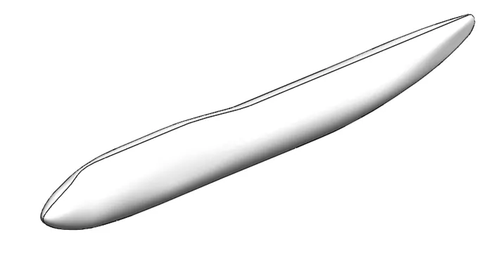
1. Fuselage
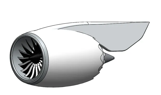
2. Engine
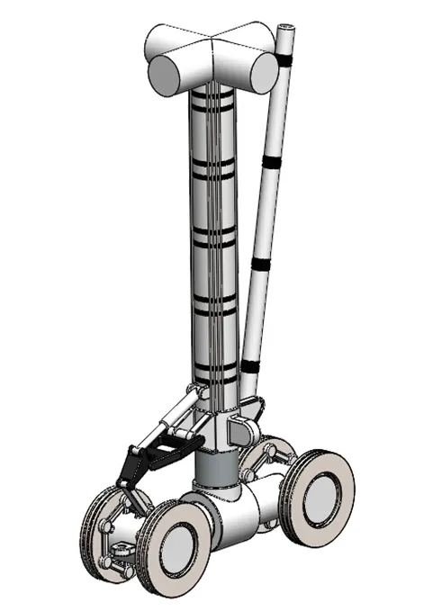
3. Main Gear Base
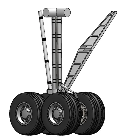
4. Main Gear Suspension Arm
5. Nose Gear Base
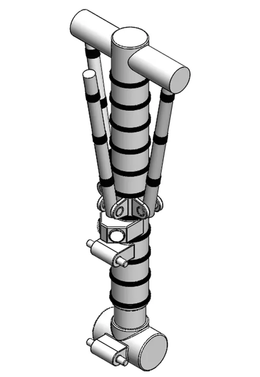
6. Nose Gear Suspension Arm
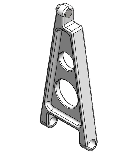
7. Wheel
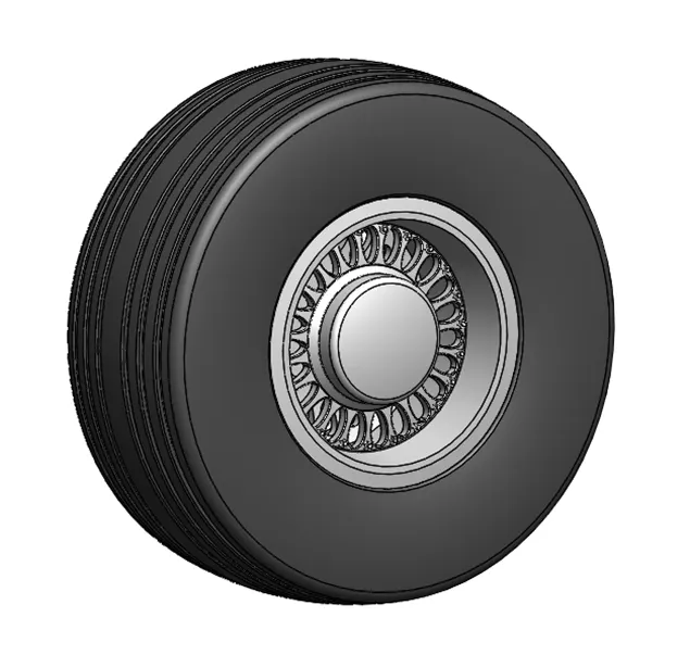
Assembly And Render Of Boeing 747
After all the componets have been designed individually in solidwoks, they are all brought together and assembled in solidworks to create the final assembly of the Boeing 747 . Since most of the components were designed in reference to the main blueprin they did not require any position change and hence when inserted into the assembly file they were correclty fixed in the required position .Few components required positioning which involved the use few different types of mates. The mates which were used are:
• Coincident mate
• Concentric mate
• Distance mate
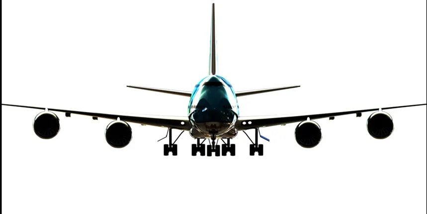
Figure 4.1 Front view
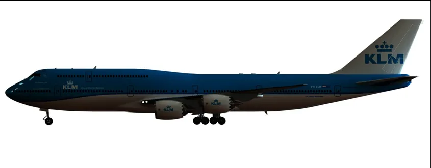
Figure 4.2 Side view
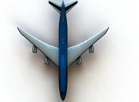
Figure 4.3 top view
Figure 4.4 perspective view
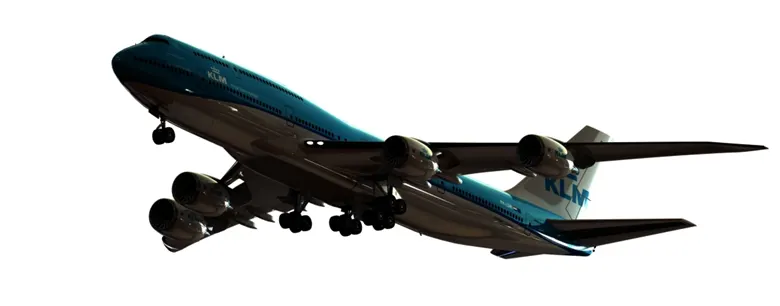
Figure 4.5 perspective view
Conclusion:
The components of the Boeing 747 were designed using solid and surface modelling techniques and finally the assembly of the Boeing 747 was done. The renders of the Boeing 747 were done in solidworks to give us a glance of how the it would look in real life.