Bird Strike - Project - 2
Objective: To simulate a Bird Strike in Aero Engine - a classic nonlinear transient dynamics problem which is solved using generic explicit solver.
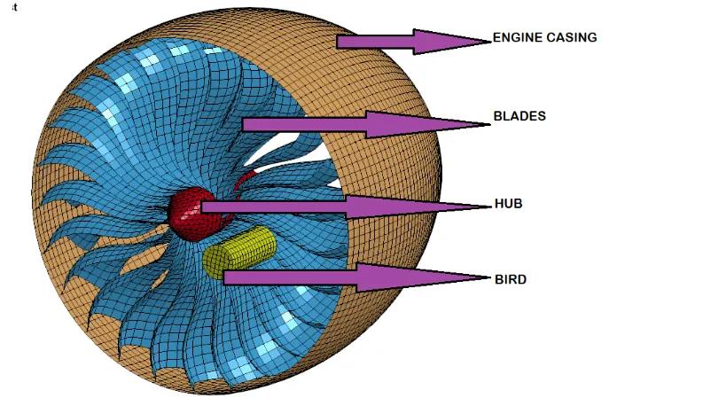
The goal of this project is to model numerically to examine the damages and failure of an aircraft engine subjected to a bird impact. For this , the work is focussed on a scenario where the bird directly impacts the rotating fan assembly, since this reperesents the most destructive part.
Unit System: kg-mm-ms
Introduction:
A bird strike refers to a collision between blades of a jet engine and an opposite approaching bird. This generally happens at low altitude flights or on a runaway, when the aircraft ascends to fly or descends for landing. With the increase in number of annual flights, the number of birdstrike incidents have also increased.
Bird strikes on aircraft mostly occurs during takeoff or landing stages as the large open field surrounding the airport provides perfect feeding, nesting and resting for largre species of birds. Most common parts of aircraft where bird strike can occur is the engine followed by leading edge (wings and empennage), windshields, nose and fuselage.
Various methods have been implemented by Airport Authorities globally to keep the birds away from the vicinity of the aircrafts which are about to takeoff or approach for landing or also in the case where the aircraft is a considerably visible lower altitiude. These approaches include remote bird sensors and hand-held laser devices for detection of birds during flight operations.
The test for bird strike on aircraft during design and manufacture involves firing a bird carass from a gas cannon onto a test unit. Later the carass is replaced with suitable density blocks often used is gelatin to ease testing.
Significance of Bird strike analysis:
Bird strike is a major threat to commercial aviation where about 90% of all foreign object damage cases are related to birds. Majority of bird causes little damage to the aircraft, however the collision is fatal to the birds involved. Most accidents occur when there is a colllision involving a bird(s) is sucked into the engines of the aircraft. In addition to property damage, colliisons between manmade structures and conveyances and birds is a major contributing factor among many others to the worldwide decline of many avian species.
Newer turbofan engines used in commercial aircraft involves large inlet diameters to achieve higher by-pass ratios and greater fuel efficiency. This larger forward facing area for each engine have a greater chance of ingesting birds. Current testing is mainly conducted with computer simulation, although final testing usually involves some physical experiments.
Before we start with assigning the parameters for differnet paths to the given input file assigned along with the project, there are some of the following things which are needed to be kept in mind.
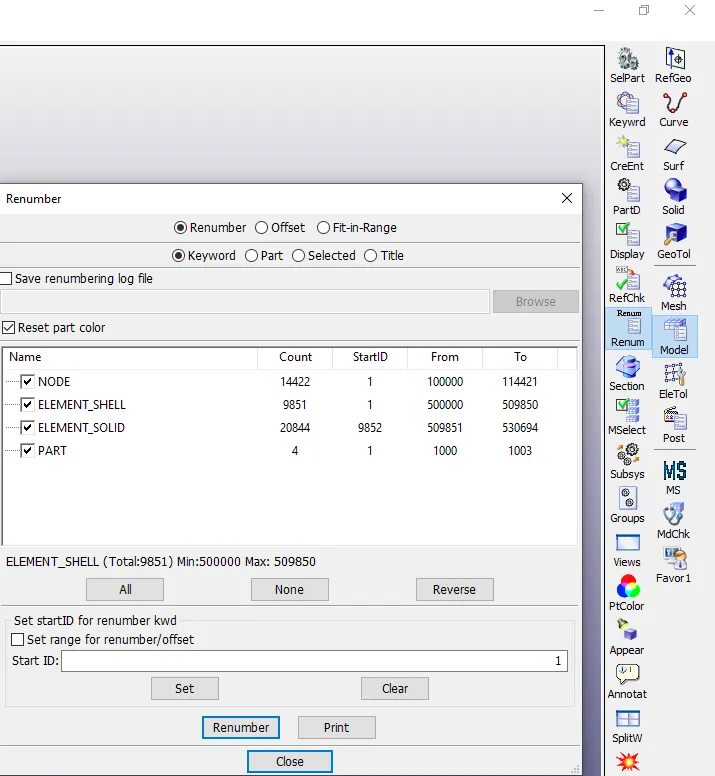
By following a consistent numbering approach, for instance 100000+ for nodes, 500000+ for elements, and 1000+ for the parts. Also all other keywords are numbered within 10000-19999 while following a range for each one.
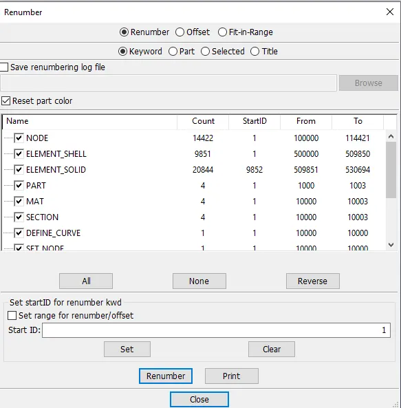
- Renumbering icon : By clicking on the renumering icon on the right toolbar, a dialog box opens and there are 4 lists of keyowrds. Rach of these keywords is ticked accordingly and the remaining ones are untickeed and a suitable ID for the ticked keyword
After adding all the other keywords related to other parameters of the part, we get
- The bird, casing, and the blades should be in different input files and there should be one main file referencing all the input files. The main file should contain only references. Control cards and boundary conditions should be there in another separate file.
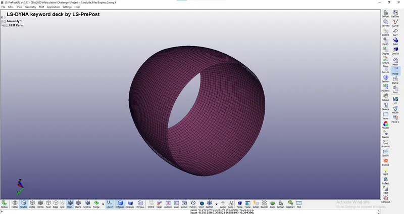
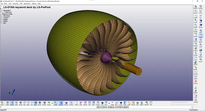
We separate all the parts in the assembly and save each part as an individual K files.
- Engine Casing
b. Hub connected by blades
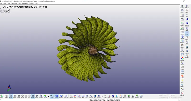
c. Striking Bird model
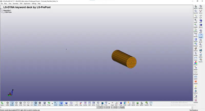
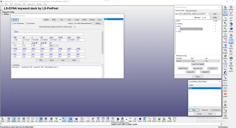
In addition we have another Input file for material modelling which provides the information for material to be added to the blade.

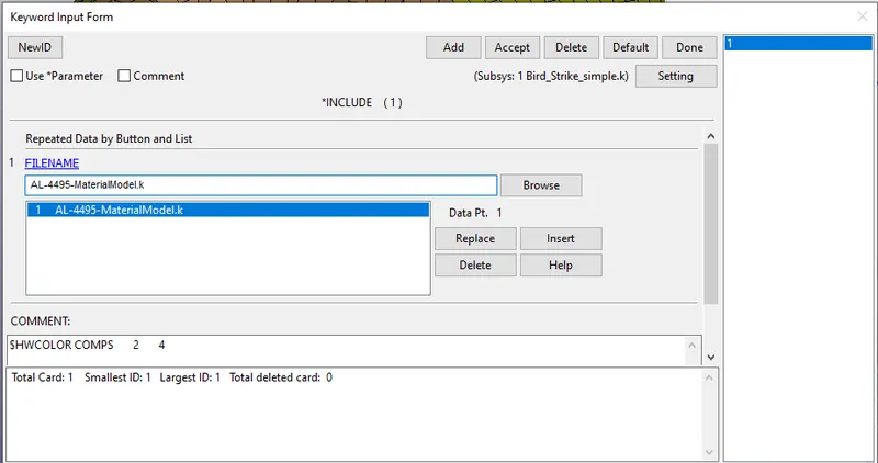
We save all the different input files generated in a single folder and open a fresh input file and connect all the subsystem file using *INCLUDE keyword
We start defining the properties of each part
*SECTION
- SHELL: For Engine casing, Blade and Striking bird
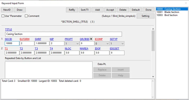
The casing section is not undergoing any kind of load or deformation during impact, there is no energy generated or disspitated in any form. Hence one can stick to reduced integration formualtion which is ELFORM Type 2. The thickness of casing is taken as 2mm since the casing is generally a sheet metal.
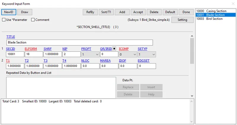
Next the blade section will undergo deformation or fracture during impact, there will be different energy generated or disspitated . Hence we need to take into account full integration formualtion which is ELFORM Type 16 over ELFORM Type 2 to account for occurences of hourglass during solving. The thickness of blade is taken as 1mm since the engine blades are very thin and made of single crystal material.
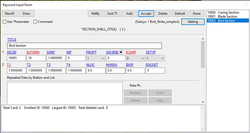
Finally the striking bird will also undergo deformation or fracture during impact, there will be different energy generated or disspitated from the moving bird. Hence we need to take into account full integration formualtion which is ELFORM Type 16 over ELFORM Type 2 to account for occurences of hourglass during solving. The thickness of bird skin is taken as 1.5mm.
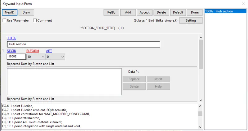
- SOLID: For Hub, the element formulation used is ELFORM type 10, as the hub is meshed using tetrahedron elements. One can also use other element formulation types like Type 4, 10 or 26.
*MAT
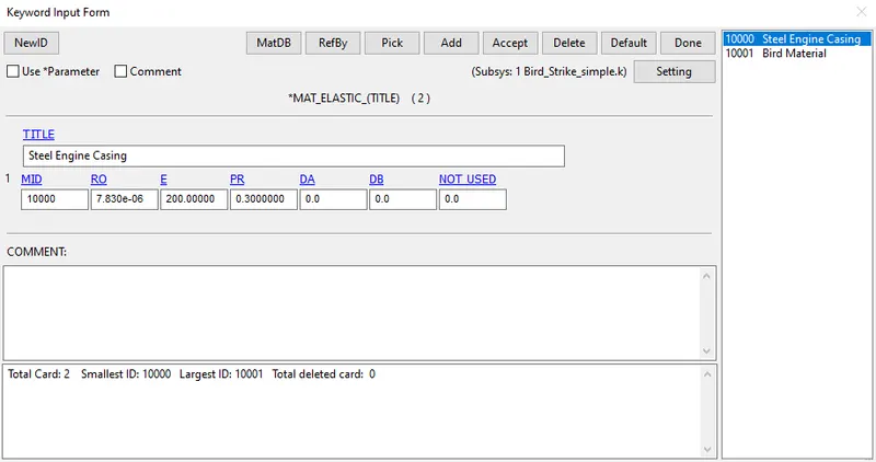
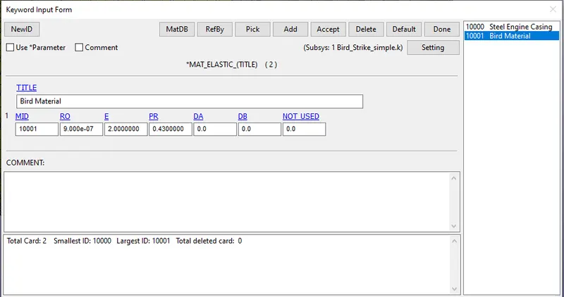
- Elastic (MAT_001): For Engine Casing, Bird
| Component | Mass Density `(\frac{kg}{mm^3})` | Poisson Ratio | Young's Modulus (GPa) |
| Engine Casing | 7.83 x `10^-6` | 0.3 | 200 |
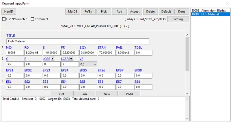
| Hub | 8.2 x `10^-6` | 0.32 | 145 |
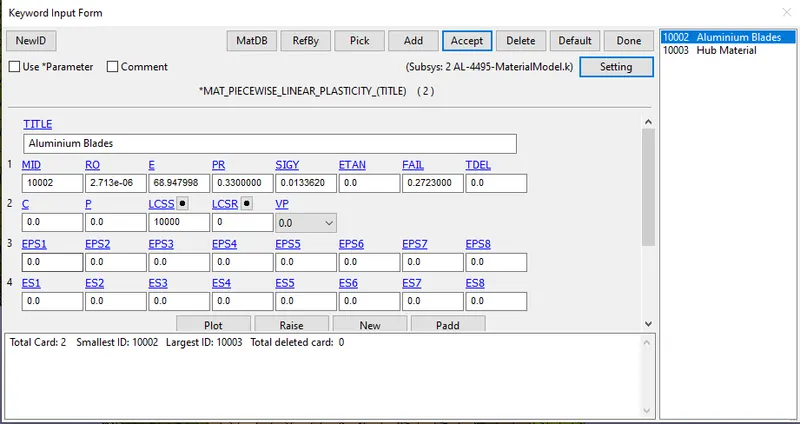
| Blades | 2.713 x `10^-6` | 0.33 | 68.947 |
| Striking Bird | 0.9 x `10^-6` | 0.43 | 2 |
- Piecewise Linear Plasticity (MAT_024): For Hub and Blades
*BOUNDARY
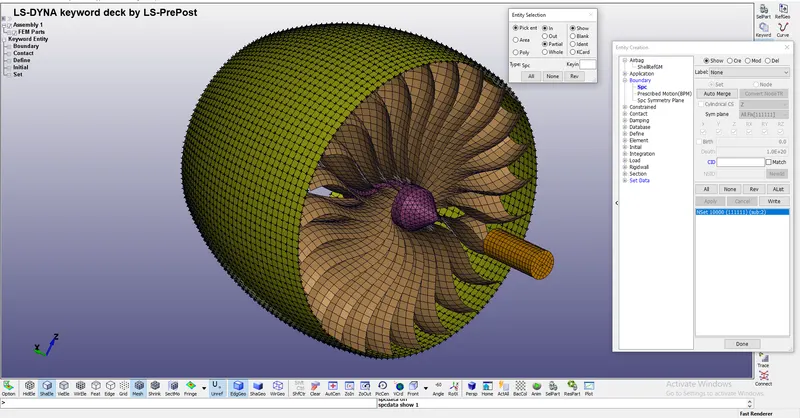
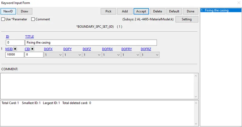
- SPC_SET: The casing of the engine is always fixed to the wing of the aircraft. So to replicate this, we fix all the nodes of the engine casing using create entity icon present in the right toolbar. By using the Boundary option among the list of the available option, we use the spc set to select all the nodes on the casing and restrain all the degrees of freedom, for fixed condition.
*INITIAL_VELOCITY_GENERATION
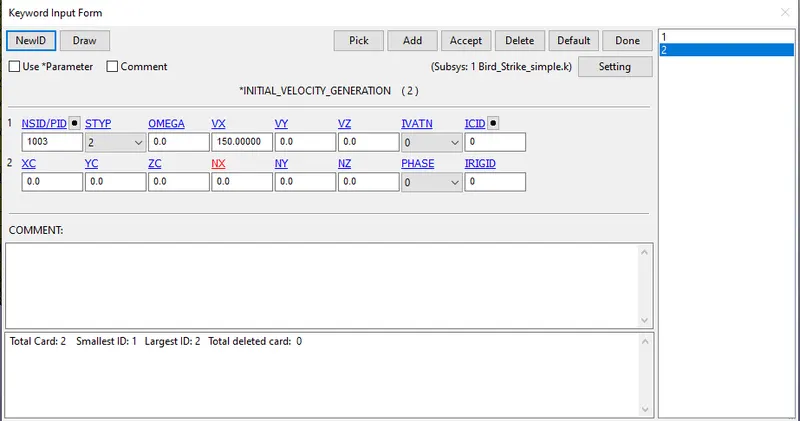
- Velocity of blades
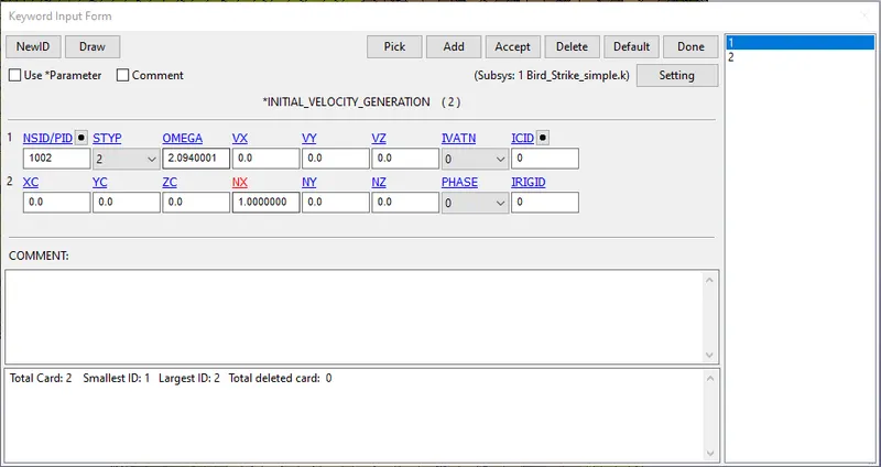
Jet Engine blades rotate at a speed of 8000~12000 rpm, during takeoff or in an event of a bird strike at low alititude A fair approximation would be to consider the velocity of blades to be 12000 rpm. So accordingly the angular velocity of the blade in rad/ms is calculated to be
`\omega =\frac{2piN}{60}` where `\omega` is calculated in `\frac{rad}{ms}`.
`\omega=\frac{2*pi*2000}{60*1000} = 2.094 \frac{rad}{ms}`
Also the hub is made to rotate about x-axis, hence the direction cosine NX is equal to 1 and the other direction consines along y and z axes are zero
- Velocity at which the bird will strike the blades
During experiments, it has been found that bird strikes occur at velocitiy of birds around 100~180m/s. For our approximation, we take the velocity of bird striking the velocity as 100m/s.
*CONTACT
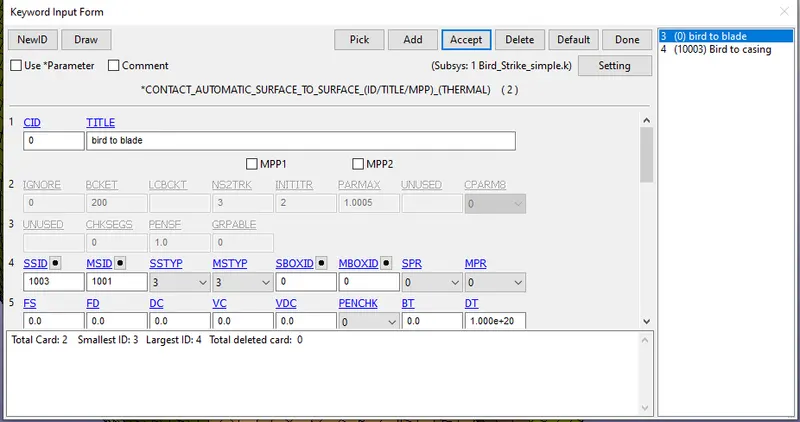
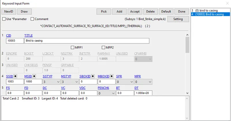
- AUTOMATIC SURFACE TO SURFACE : In order to avoid penetrations between the bird to blade during impact, Automatic Surface to Surface contact definition is used and again once the impact is caused, there is a possibility of the bird penetrating into the casing and hence the same contact card is called between bird and engine casing.
In the first contact definition the bird becomes the slave and the blade is the master surface by calling the SSTYP and MSTYP as 3.
Similarly, in the second contact definition the bird becomes the slave and the engine casing is the master surface by calling the SSTYP and MSTYP as 3.
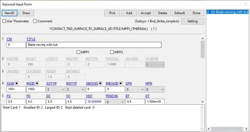
- TIED SURAFCE TO SURFACE: During rotation of the hub, the surface of the blade should move in synchronous to the surface of the hub during hub rotating at higher rpms and also the penetration between them is needed to be avoided. In this contact definition, the blade becomes the slave and the hub is the master surface by calling the SSTYP and MSTYP as 3.
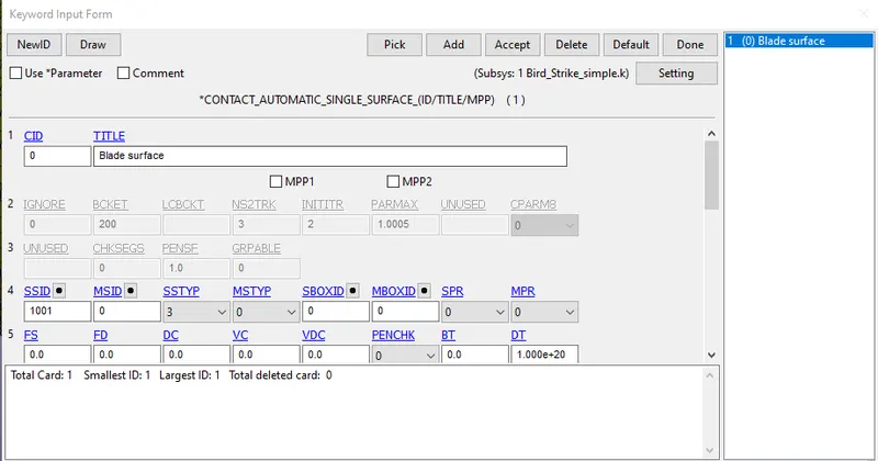
- AUTOMATIC SINGLE SURFACE : During rotation of the blades, care should be taken that the blades should not come in contact or penetrate with each other. Hence this contact definition is needed to be called by considering the blades to be the slave surface by calling the SSTYP as 3.
*CONTROL
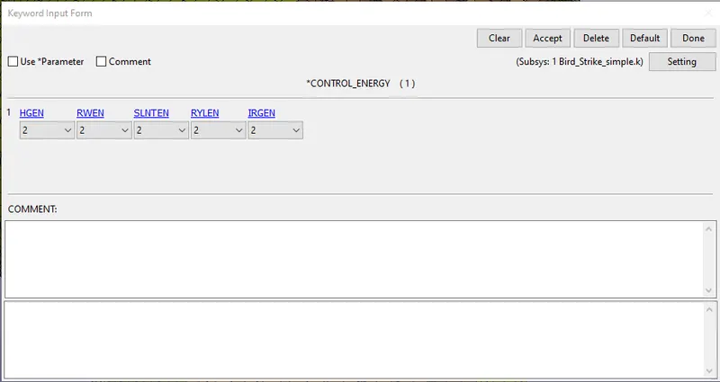
- ENERGY : All the energy considered for conducting the analysis are considered for final output calculating energies.
- TIMESTEP
Without Mass Scaling
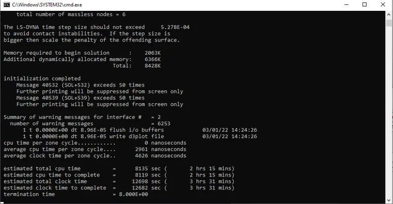
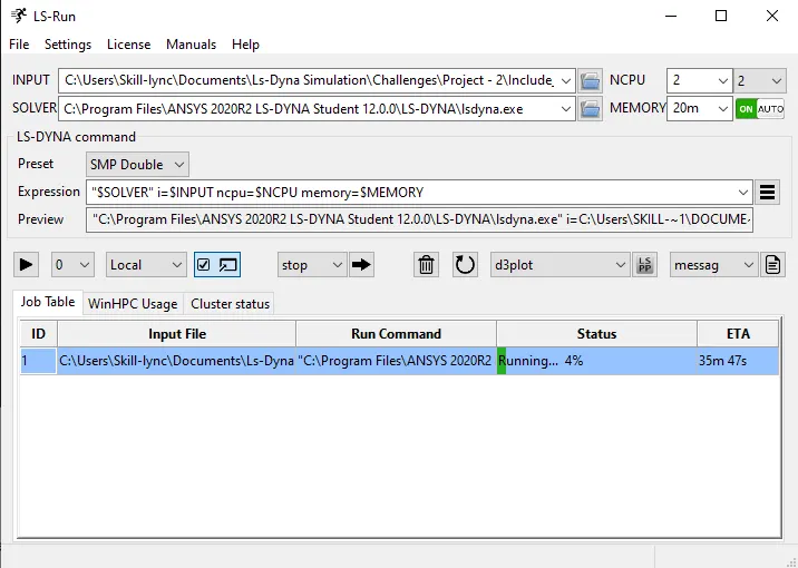
If we do not scale the mass of the nodes, then the problem will take to complete for a longer duration. Though in the command prompt it shows that it takes more than 3 hr 31 min. But in actual LS-Run window the time taken to complete the problem will be different. It is advised to take note of the simulation time from LS-Run window.
With Mass Scaling
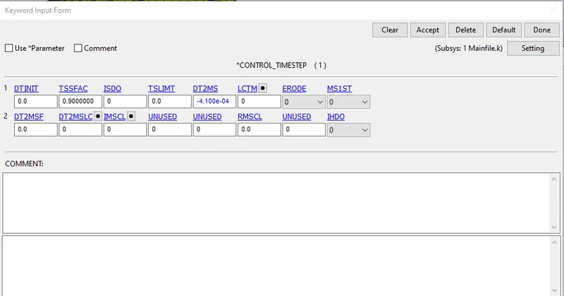
For convenience, to reduce the time taken to complete the simulation, we take into account an 8% mass is added to the existing nodal masses. We slowly increase the DT2MS parameter in the negative sense present in the *CONTROL_TIMESTEP card.
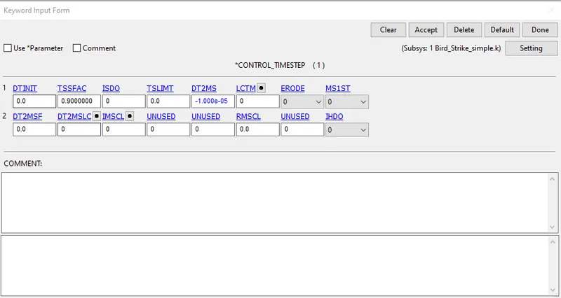
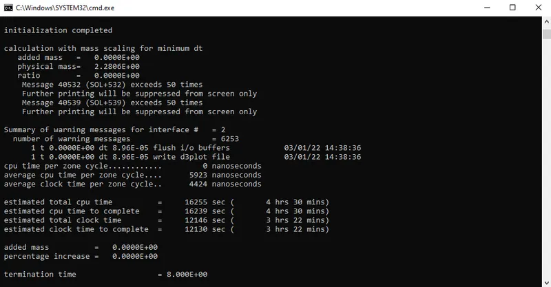
There is no increase in added mass as seen and hence we need to increase the DT2MS further. We start with DT2MS as -1x`10^-6` and increase each time by increments of 0.2.
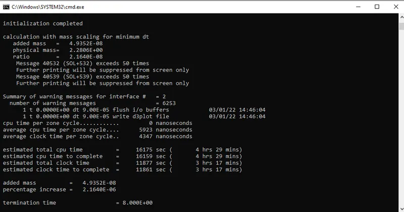
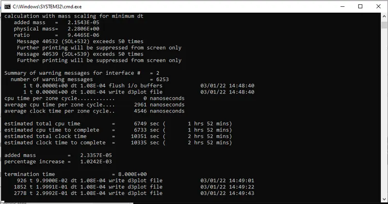
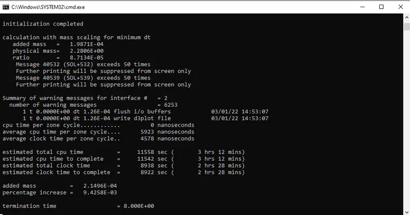
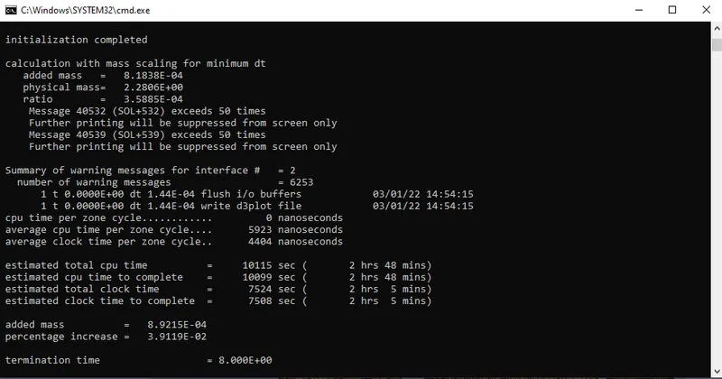
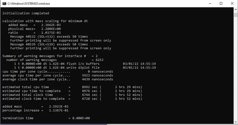
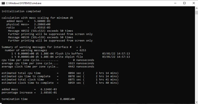
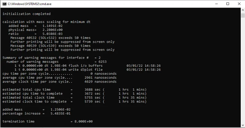
We finally settle the DT2MS value to be -4.1 x `10^-4`such that the percentage increase is found out to be 8.02%
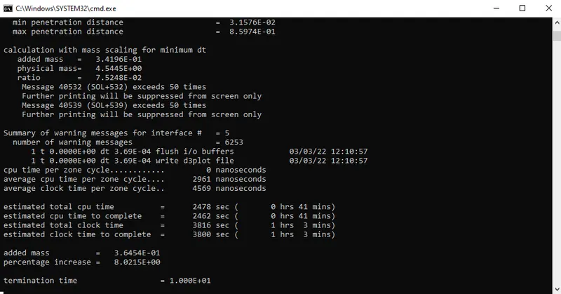
Kindly note that it is always important to look at the LS-Run window for actual time of completion of the simulation. In this case, by mass scaling the duration of the simulation went for 10mins.
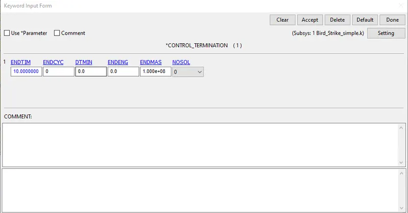
- TERMINATION: The end time for the simulation is taken to be 10ms.
*DATABASE
- Binary D3PLOT : This card is called to see the results of the animated output for every 0.1ms.
- ASCII Files - GLSTAT, MATSUM
----------------------------------------------------------------------------------------------------------------------------------------
RESULTS/OUPUTS
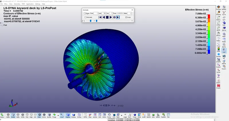
Animated image before the bird is about to strike the blades
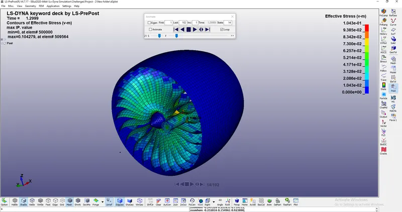
Animated image where the bird is nearing to strike the blades
Note: The animated file or the d3plot file is uploaded in the resource section as a .mov file.
Other output extracted from the analysis includes the following:
- Energy Plot (GLSTAT)
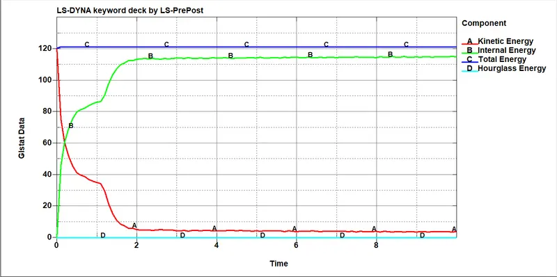
- In explicit analysis, when the bird hits the blade at a high velocity, the kinetic energy and the internal energy of the entire system go out of phase and hence the total energy of the system remains constant from the law of conservation of energy.
- There is no formation of hourglass energy as element formulation type16 was used for both blade and bird while assigning their respective sections.
- The above plot justifies the correct formulation of the simualtion.
- Effective stress plot
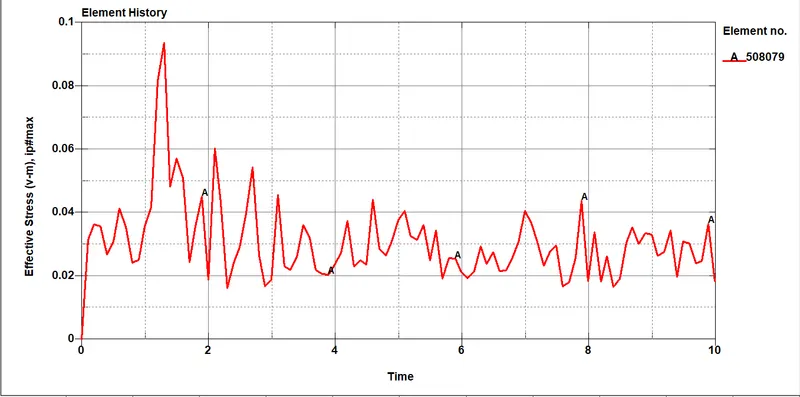
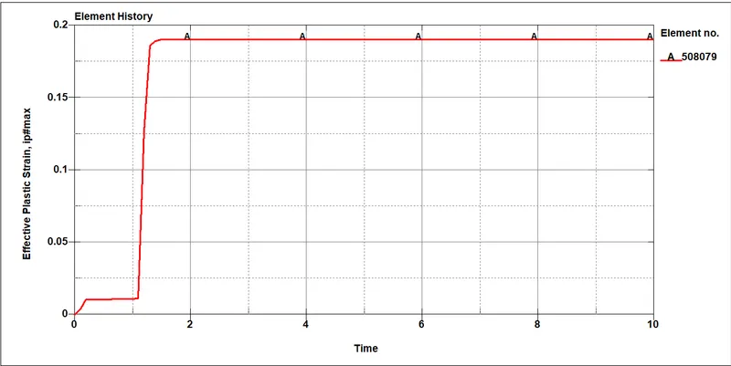
- Effective plastic strain plot
CONCLUSION
- The bird strike problem is a highly non-linear, transient dynamic problem that can be simulated using explicit solvers within a very optimized time.
- For larger models, the use of multi-file systems makes it easier for modelling as multiple people can work with the multiple subsystems simultaneously.
-
The standarized numbering system makes things further easier for CAE engineers.