Bird Strike - Project - 2
AIM: To simulate Bird Strike impact on Aero Engine.
1. Introduction
Even though the vast number of reported bird strikes have little or no impact on the continued safe flight, a small number of encounters, usually involving flocks of birds, and especially flocks of large birds, can severely damage aircraft or their engines, rendering them unfit to fly. As a result, current aircraft certification standards include requirements to demonstrate bird impact resistance in both the airframe and the engine.
The most important determinant of damage potential for any given impact is the impact speed. As we know
`E_(KE) = (1/2)*m*v^2`
where `E_(KE)`represent Kinetic Energy`
m and v represent the mass and velocity of the impacting body respectively.
Evidently, the aeroplane's speed, instead of the bird's, covers nearly all of the relative speed of impact, so that, with the exception of very small aircraft, aircraft speeds are directly proportional to the damage potential for collision with a specific object.
2. Numbering Approach Guidelines
| Components | Nodes | Elements | Part ID | Keyword | Element Type |
| Engine Casing | 100000-104095 | 500000-503967 | 1000 | 11001,11002... | SHELL |
| Blades | 200000-206252 | 600000-605472 | 2000 | 12001,12002... | SHELL |
| HUB | 300000-303981 | 700000-720843 | 3000 | 13001,13002... | SOLID |
| BIRD | 400000-400411 | 800000-800409 | 4000 | 14001,14002... | SHELL |
3. Part Modelling Definition
3.1 Engine Casing:
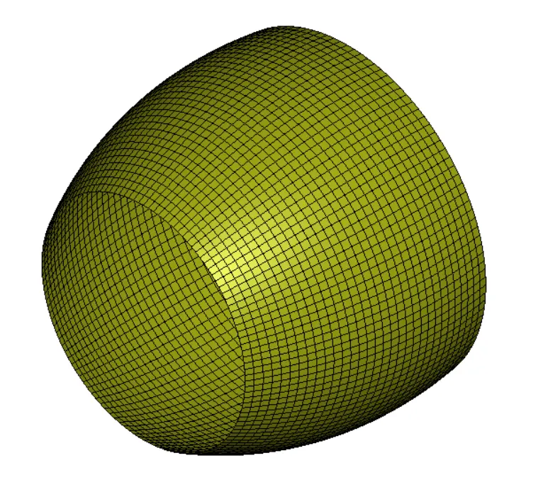
For the given Engine Casing, Part ID =1000
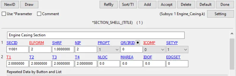
Section Definition: The model contains shell elements, thus the shell section has been utilised with SECID = 11001 and ELFPRM = 2 as the casing will remain stationary with 2mm thickness.
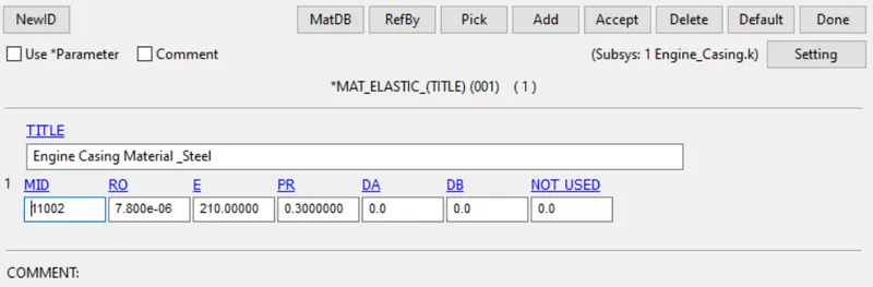
Material Definition: MAT 001 is utilised and MAT ID 11002 is defined corresponding to Part ID -1000.
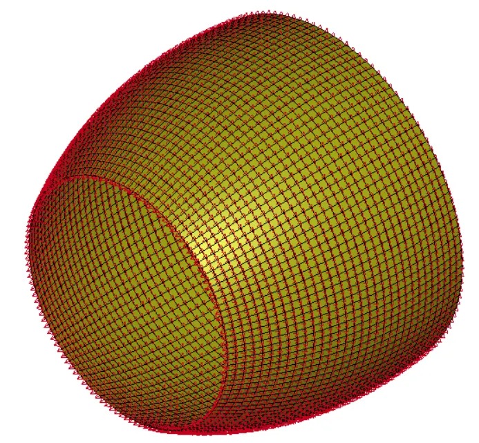
Boundary Conditions: complete geometry has been constrained in all the 6 DOFs.
3.2 Blades:
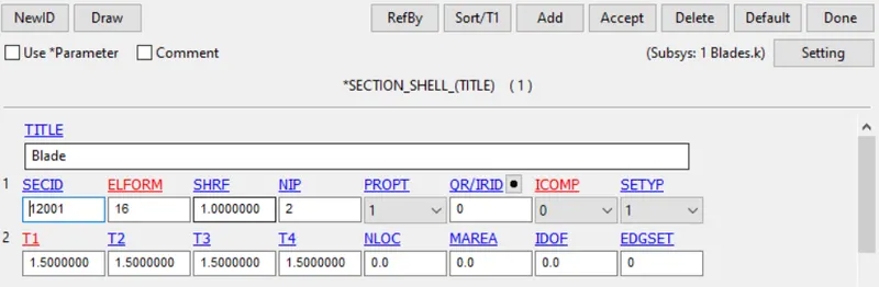
For the given Blade, Part ID =2000
Section Definition: The model contains shell elements, thus the shell section has been utilised with SECID = 12001 and ELFPRM = 16 with 1.5mm thickness was defined, as the blades will undergo deformation due to bird impacting on the surface of the blade.
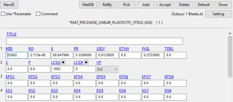
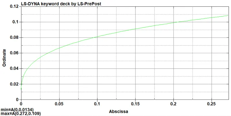
Material Definition: MAT 024 is given as the blade material with load curve defined and MAT ID 12002 is defined corresponding to Part ID -2000.
Defined Load Curve
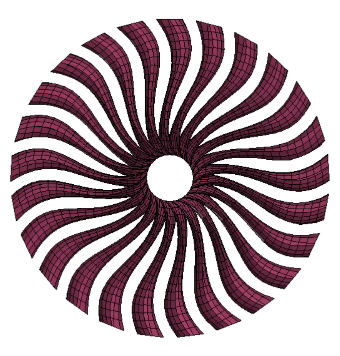
Boundary Conditions:
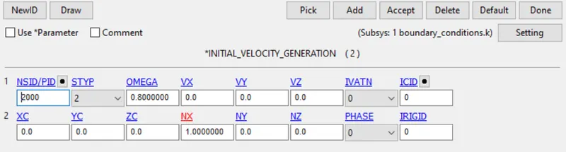
To define the angular motion of the blades, Initial velocity with omega equal to 0.8 was defined.
3.3 Hub:
For the given Engine Casing, Part ID =3000
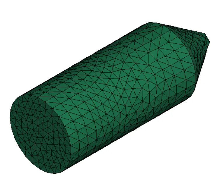
Section Definition: The model contains tetrahedron elements, thus EFFORM = 4 was defined in SECID = 13001. 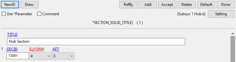
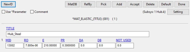
Material Definition: MAT 001 is utilised and MAT ID 13002 is defined corresponding to Part ID -1000.
3.4 Bird:
For the given Bird Model, Part ID =4000
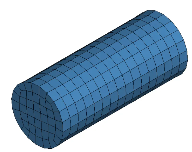
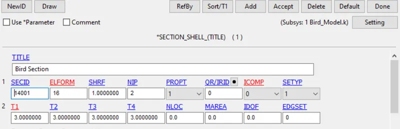
Section Definition: The model contains shell elements, thus the shell section has been utilised with SECID = 14001 and ELFORM = 16 with 2mm thickness. Advanced element formulation was introduced since the interaction between bird and blades will lead to deformation.
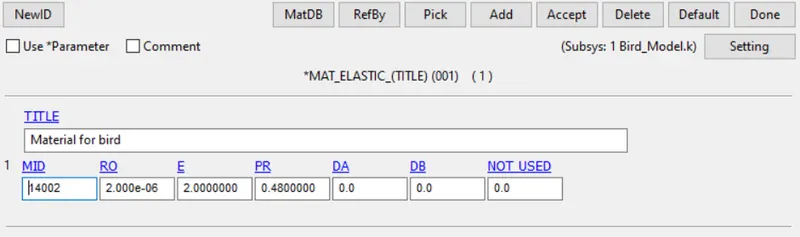
Material Definition: MAT 001 is utilised and MAT ID 14002 is defined corresponding to Part ID -4000.
Boundary Conditions: To define the linear motion of the bird model, Initial velocity with X -directional velocity of 25mm/ms was defined. 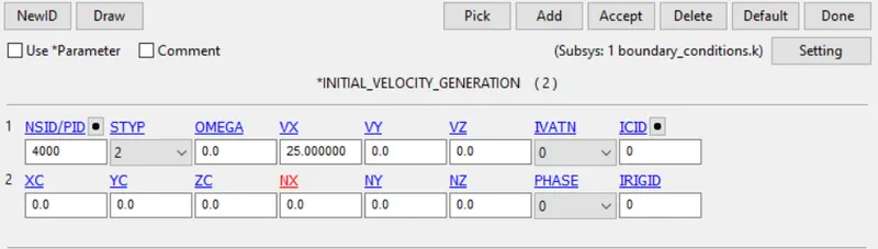
4. Contact Definition
The different contact applied for an accurate simulation of the model includes :
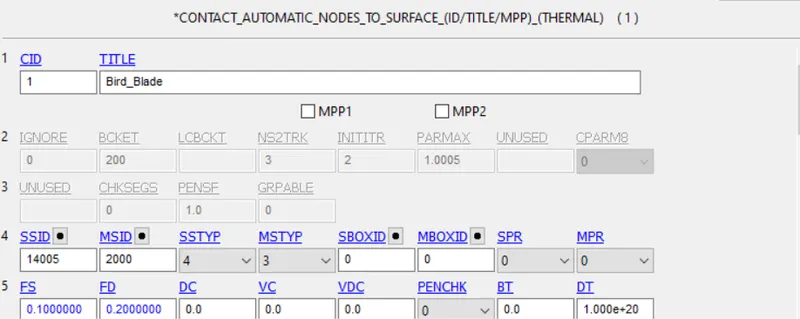
4.1 Contact between Bird and Blade was defined using Nodes_to_Surface contact.
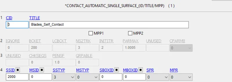
4.2 To prevent self penetration of the blades during failure, single surface contact was utilised.
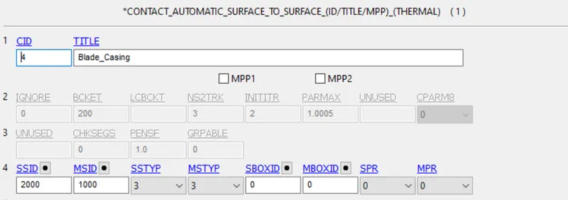
4.3 Contact between Blade and Casing was defined using Surface to Surface contact.
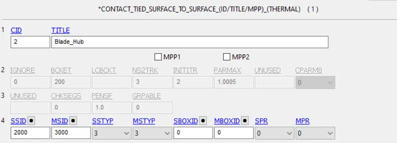
4.4 The blades are fixed to the hub using the tied surface to surface.
5. Control Card
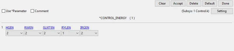
Energy Control - To determine energy output, control energy was determined.
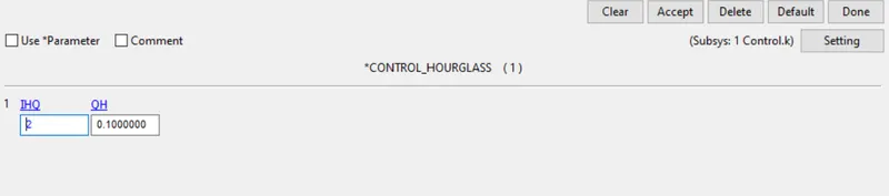
Hourglass control definition
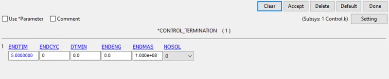
Control Termination
6. Description of the Solution Process
Since the given problem consists of multiple moving parts, systematic file inclusion was adopted in the following manner.
| SI. No. | Action | Feedback | Correction |
| 1. | Defining material properties and sections for each given part in every individual file, maintaining the keyword numbering sequence. | Given material data seemed to have unformatted load curve define | The load curve was corrected and manually included in the keyword file. |
| 2. | The inclusion of Blade and Hub only to determine correct rotation speed and avoid numerical instability. | The rotation speed appeared to be out of order. | The omega value was calibrated to obtain the solution in respective order. |
|
3. |
Adding the engine casing with fixed boundary conditions. | NIL | NIL |
| 4. | Adding the bird model and impact on the blades. | The bird impact speed error. | The impact speed was calibrated based on data available in the open literature. |
| 5. | Termination time calibration | NIL | NIL |
7. Result
7.1 Energy Balance
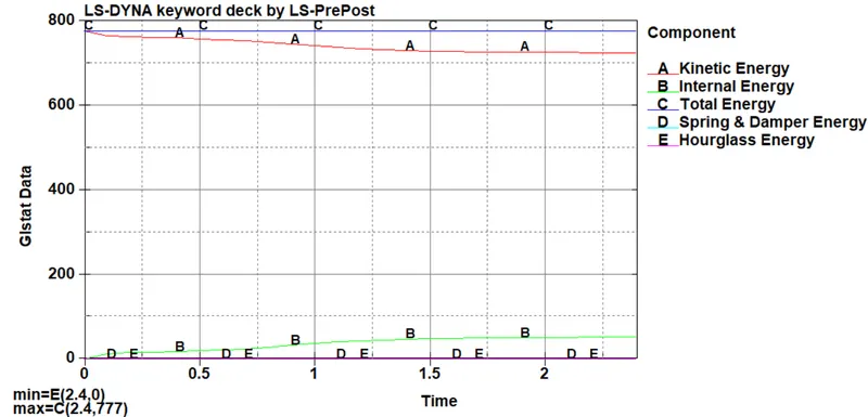
The maximum energy of the system is 777KN-mm i.e. Total Energy. For a stable simulation, apart from Internal and Kinetic energy, the energy lost by other means should be much below 5% of the total energy of the system. Form the system, the same was followed signifying the validity of the numerical simulation.
7.2 Max Von-Mises Stress
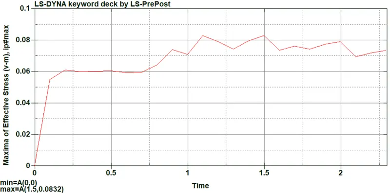
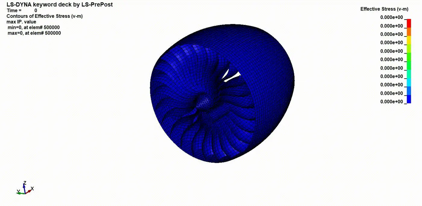
From the graph, it was observed that the maximum stress obtained in the Blade was about 0.0832 GPa. In the defined material, the yield stress was defined to be 0.0133620 GPa. The max stress in the blade reached 500% more than the yield stress, resulting in catastrophic damage to the engine blades.
7.3 Max Effective Strain
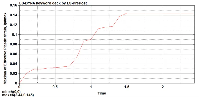
the obtained maximum strain is about 0.145 at 2.44 ms, clearly depicting the plastic deformation.
7.4 Mass Scaling Effect
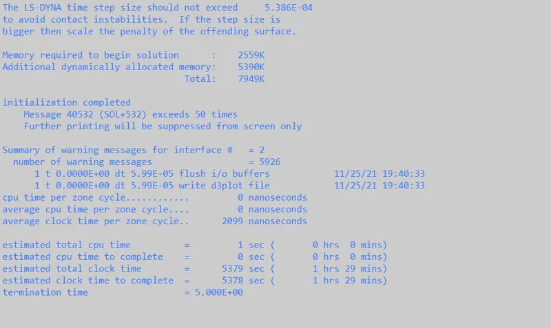
Without mass scaling, the run time is about 1hr 29 mins.
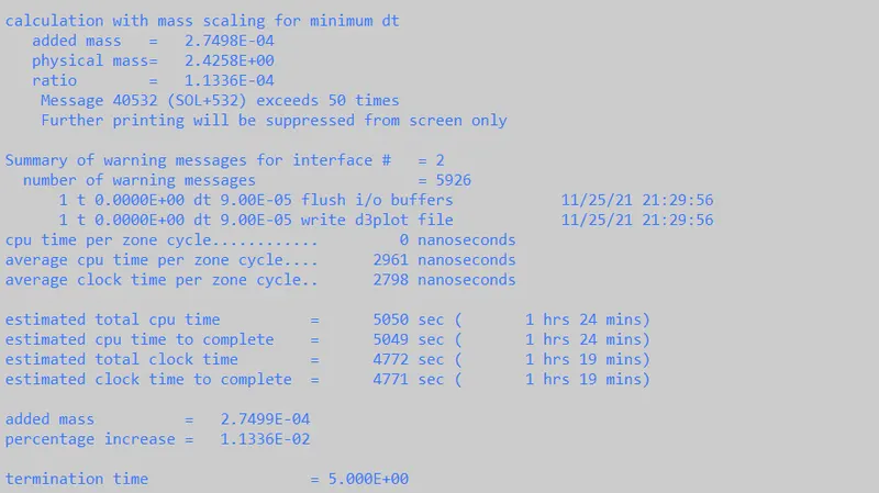
Mass Scaling with DT2MS = -1e-4, resulted in 2.75e-4 kg addition of mass and an increase of 0.0011% which is below 10%, resulting in 10min of run time.
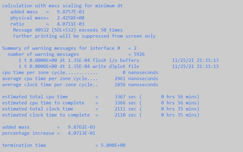
Mass Scaling with DT2MS = -1.5e-4, resulted in 9.876e-3 kg addition of mass and an increase of 0.40% which is below 10%, resulting a run time of 35min.
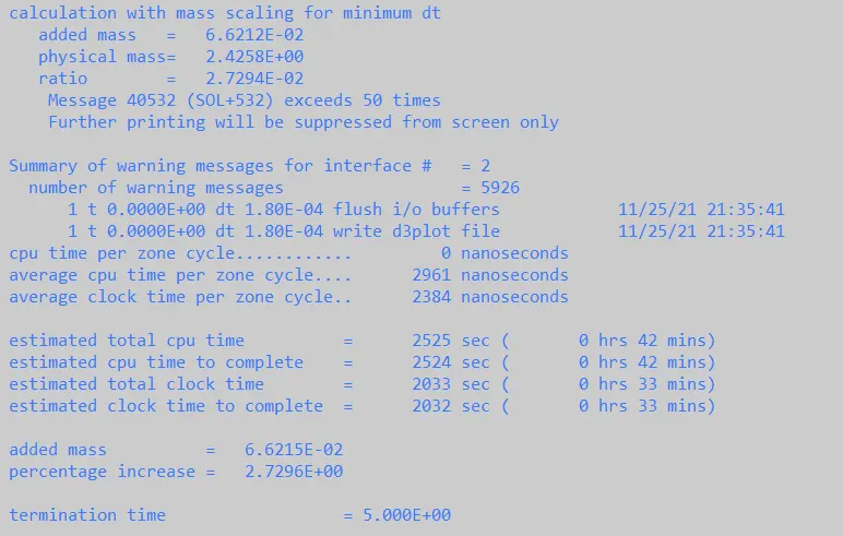
Mass Scaling with DT2MS = -2.0e-4, resulted in 6.621e-2 kg addition of mass and an increase of 2.72% which is below 10%, resulting in a run time of 33min.
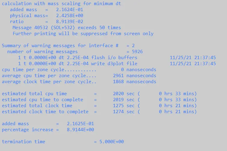
Mass Scaling with DT2MS = -2.5e-4, resulted in 2.16e-1 kg addition of mass and an increase of 8.91% which is below 10%, resulting in a run time of 21min.
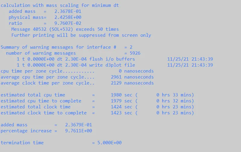
Mass Scaling with DT2MS = -2.55e-4, resulted in 2.36e-1 kg addition of mass and an increase of 9.76% which is below 10%, resulting in a run time of 23min.
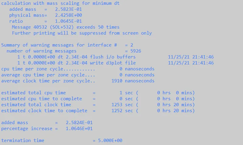
Mass Scaling with DT2MS = -2.6e-4, resulted in 2.58e-1 kg addition of mass and an increase of 10.64% which is above 10%, thus needed to be avoided.
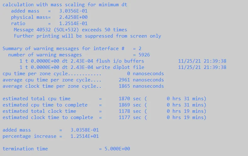
Mass Scaling with DT2MS = -2.7e-4, resulted in 3.03e-1 kg addition of mass and an increase of 12.51% which is above 10%, thus needed to be avoided.
CONCLUSION
- Bird Impact using the Lagrangian model has been utilised to simulate the effect of bird strike on rotating compressor blades.
- Plastic Deformation was observed due to Bird Impact at 25mm/ms.
- Mass Scaling was utilised and a DT2MS value of -2.5e-4 seemed appropriate.