Bird Strike Simulation in LS-DYNA
Objective: To perform and simulate the non-linear case of Birdstrike in Aero-engine using explicit analysis in LS-Dyna.
Procedure:
- The given keyword file BIRD_STRIKE consists of nodes and elements for all the four parts collectively, i.e., Engine casing, Blade, Hub, and Blade.
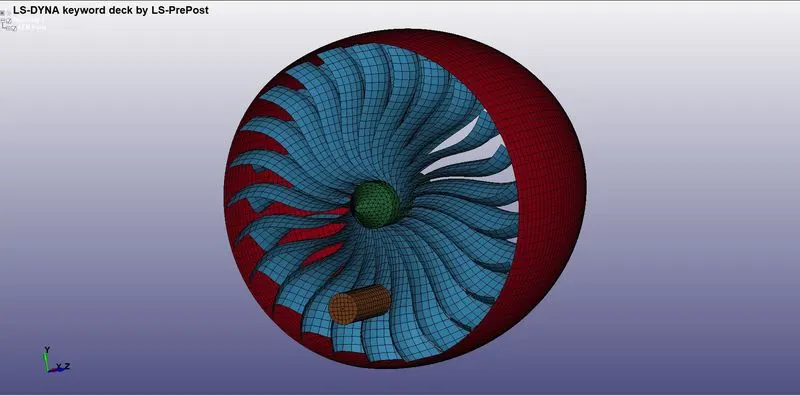
Fig 1: Model and mesh information in the provided keyword file.
- Separate the given parts by assigning the keywords file. Those parts are distributed and saved .k keyword file.
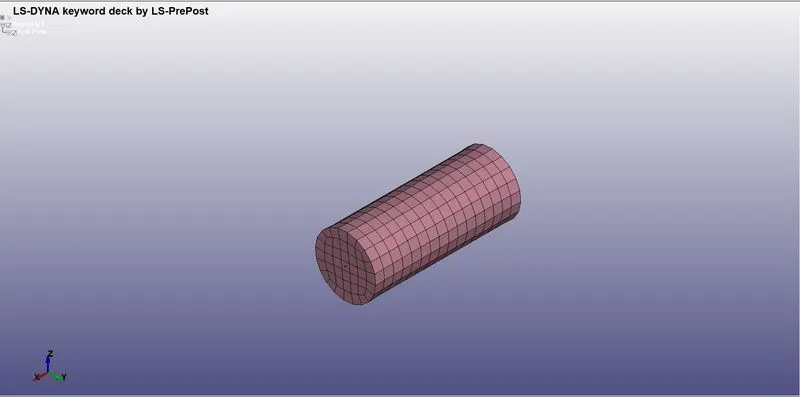
Fig 2: bird model separated.
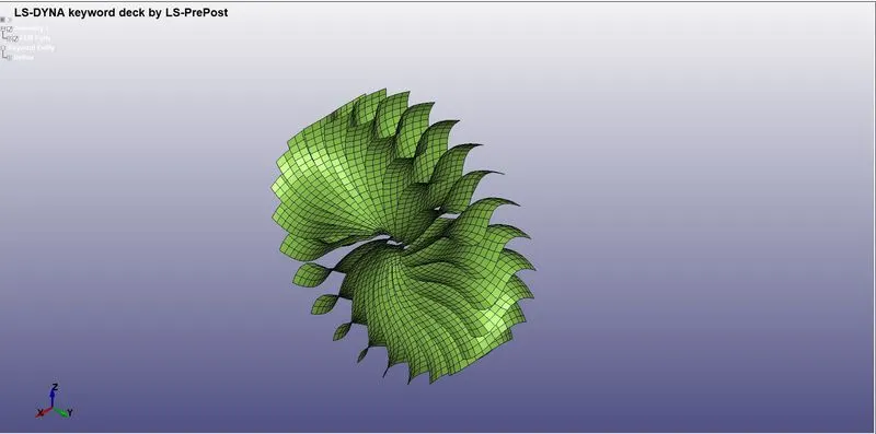
Fig 3: blades model separated.
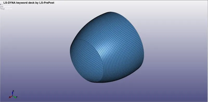
Fig 4: engine casing model separated.
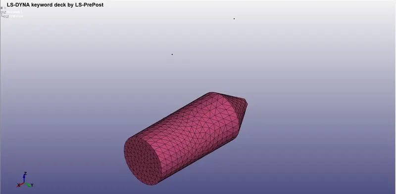
Fig 5: hub model separated.
Material and section assignment to each separated model:
- For the bird model, *MAT_ELASTIC card material is selected, and the following properties are assigned.
- The given properties are Density: 2.000e-6, Young's Modulus: 2.000, Poisson Ratio: 0.47.
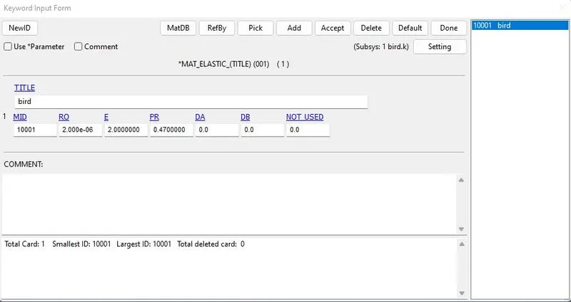
Fig 6: MAT_ELASTIC card is defined.
- Section card is created with Element formulation of 16 (Fully integrated shell element modified for higher accuracy).
- The thickness of the bird model is assigned to be 15 mm.
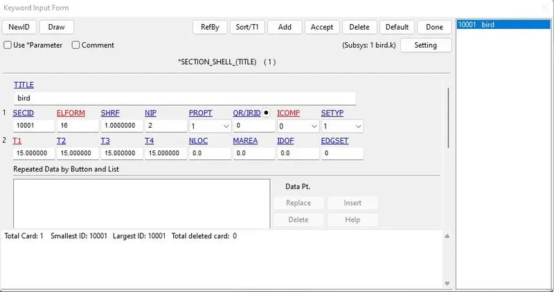
Fig 7: Shell section is defined.
- Assign the part with the material and section card.
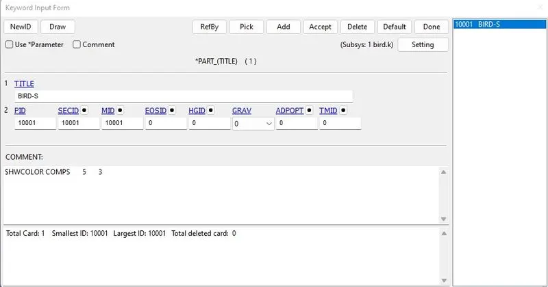
Fig 8: Section and material are assigned to the part.
- For the blade model, *MAT_PIECEWISE_LINEAR_PLASTICITY card material is selected, and the following properties are assigned.
- The given properties are Density: 2.713e-06, Young's Modulus: 68.947998, Poisson Ratio: 0.33, Yield stress: 0.0133620 and failure flag: 0.2723.
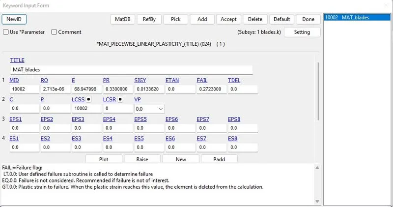
Fig 9: MAT024 card is defined.
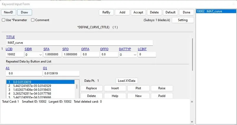
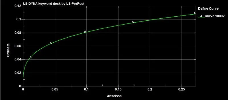
Fig 10: Stress-strain curve definition.
- Section card is created with Element formulation of 16 (Fully integrated shell element modified for higher accuracy).
- The thickness of the blade model is assigned to be 2 mm.
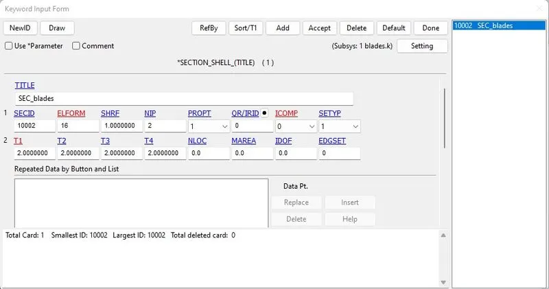
Fig 11: Shell section is defined.
- Assign the part with the material and section card.
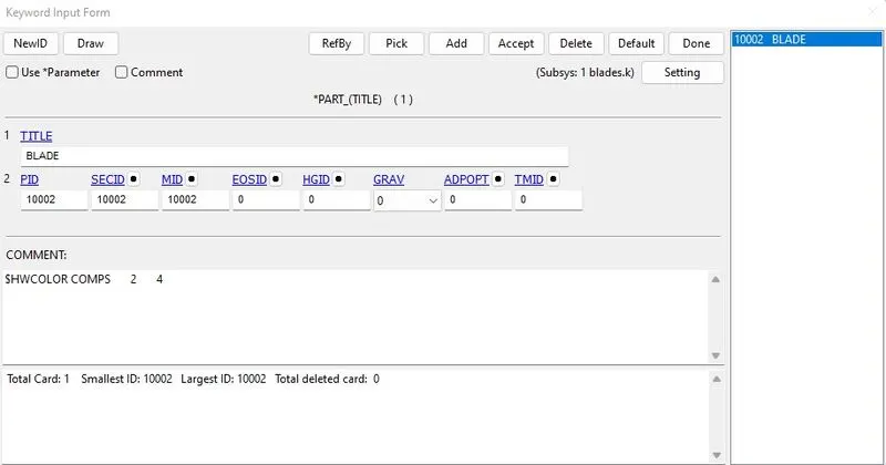
Fig 12: Section and material are assigned to the part.
- For the engine casing model, *MAT_ELASTIC card material is selected, and the following properties are assigned.
- The given properties are Density: 7.8e-06, Young's Modulus: 210, Poisson Ratio: 0.33.
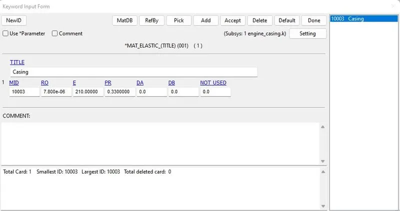
Fig 13: MAT_ELASTIC card is defined.
- Section card is created with Element formulation of 16 (Fully integrated shell element modified for higher accuracy).
- The thickness of the engine casing model is assigned to be 1 mm.
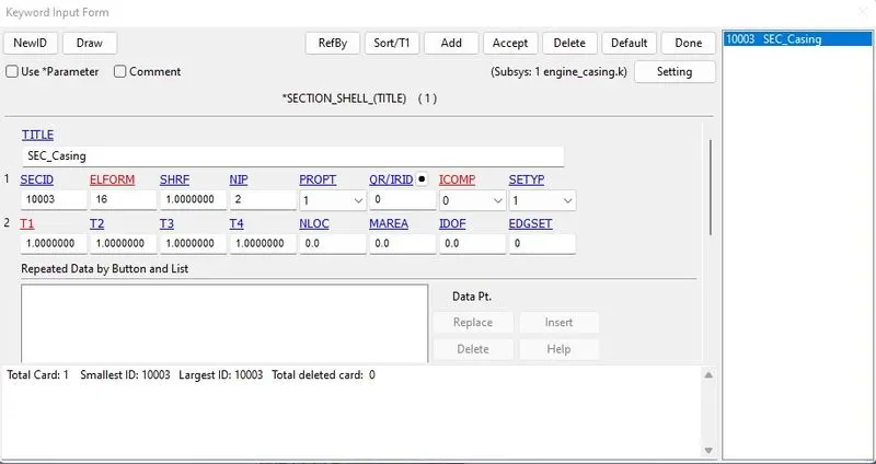
Fig 14: Shell section is defined.
- Assign the part with the material and section card.
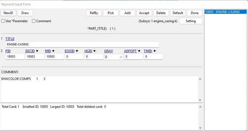
Fig 15: Section and material are assigned to the part.
- For the hub model, *MAT_PIECEWISE_LINEAR_PLASTICITY card material is selected, and the following properties are assigned.
- The given properties are Density: 8.2e-6, Young's Modulus: 145, Poisson Ratio: 0.3, Yield stress: 0.81, and tangent modulus: 70.
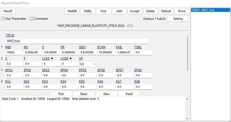
Fig 16: MAT024 card is defined.
- Section card is created with Element formulation of 10 (1 point tetrahedron).
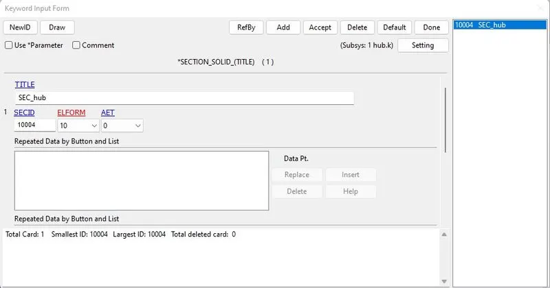
Fig 17: Solid section is defined.
- Assign the part with the material and section card.
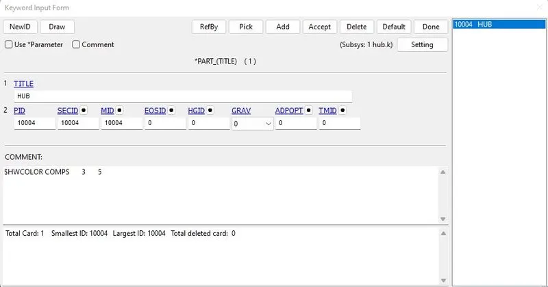
Fig 18: Section and material are assigned to the part.
- All the FE models saved separately for the bird, engine case, blade, and hub are included in a single main.k model file.
- Using the keyword file *Include→">→Include allows for providing a new FE model.
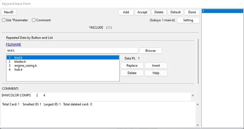
Fig 19: All the part keyword files are included in a single keyword file.
Contact definition:
- The blades should rotate according to the hub; *CONTACT_TIED_SURFACE_TO_SURFACE is used to tie the surface of the hub with the blade and blade as a slave and hub as master.
- Contacts are created using Part ID type, SSTYPE=3 & MSTYP=3.
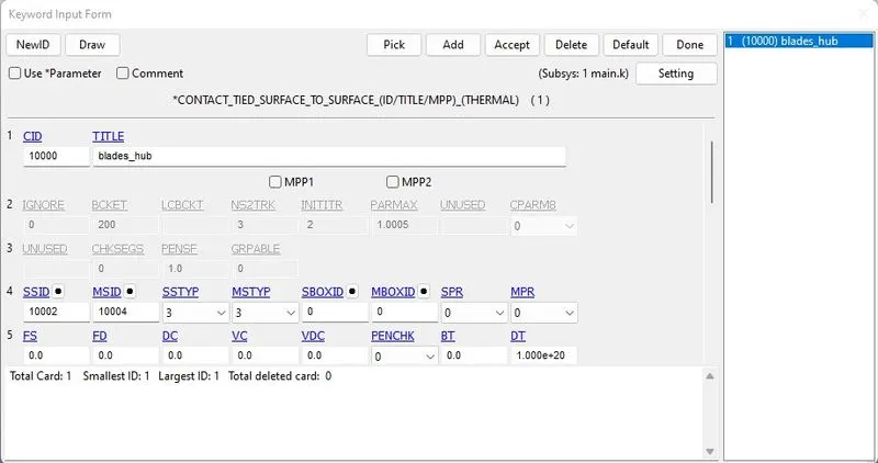
Fig 20: Tied contact is established between the blades and the hub.
- When the bird hits the blade, *CONTACT_AUTOMATIC_SURFACE_TO_SURFACE is used, keeping the bird as a slave and the blade as a master.
- Contacts are created using Part ID type, SSTYPE=3 & MSTYP=3.
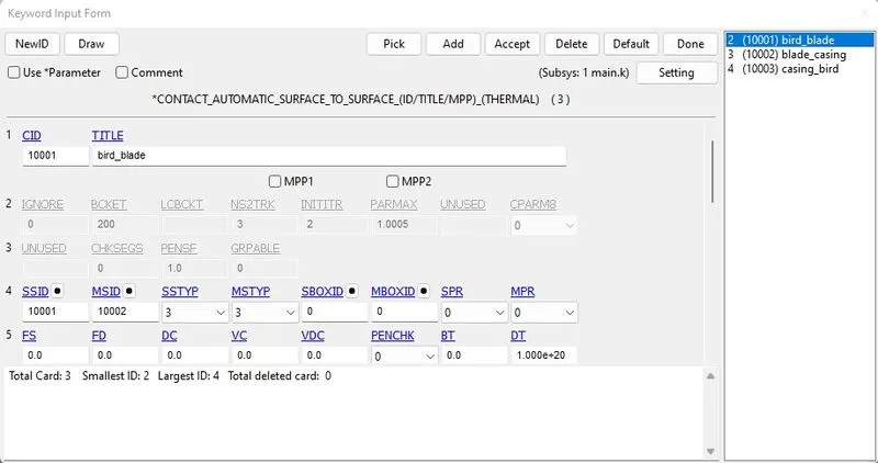
Fig 21: Contact is established between the bird and the blades.
- The blade should not suppose to penetrate the casing. Again *CONTACT_AUTOMATIC_SURFACE_TO_SURFACE is used as the blade to be slave and case as a master.
- Contacts are created using Part ID type, SSTYPE=3 & MSTYP=3.
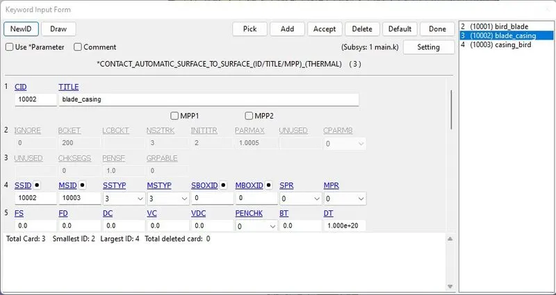
Fig 22: Contact is established between the casing and the blades.
- Also, the bird does not suppose to penetrate the casing. Again *CONTACT_AUTOMATIC_SURFACE_TO_SURFACE is used, keeping the case to be slave and bird as a master.
- Contacts are created using Part ID type, SSTYPE=3 & MSTYP=3.
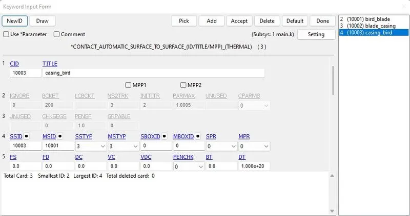
Fig 23: Contact is established between the casing and the bird.
- Finally, once the bird hits the blades, the deformed blades are not supposed to penetrate with each other. So *CONTACT_AUTOMATIC_SINGLE_SURFACE is used.
- Here for the single contact, we used Part ID type, SSTYPE=3 & MSTYP=0.

Fig 24: Self-Contact is established between the blades.
Boundary Condition:
SPC:
- Though the turbine engine case is supposed to be fixed at the airplane wing, it must be constrained in all directions, i.e., Translation and Rotation.
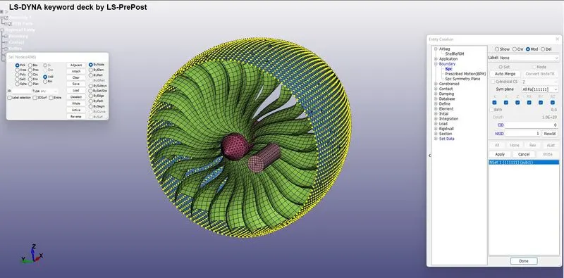
Fig 25: The casing is constraint is all DOF's.
Initial Velocity:
- The average velocity of the bird travels to be approximately 20 to 80 mm/ms.
- Here the velocity of the bird is assigned to be VX=30 mm/ms along the X-axis translative direction.
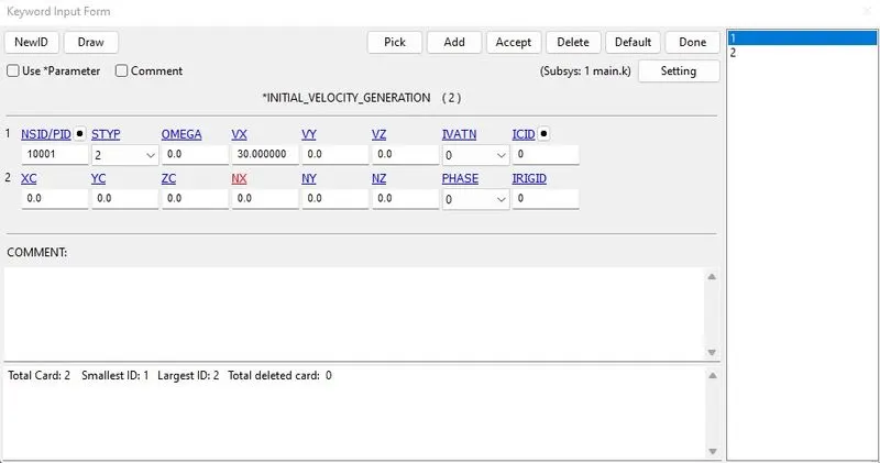
Fig 26: Velocity in the x-direction is given to the bird model.
- The angular velocity of the blades is roughly around 3000 to 20000 RPM.
- Considering 5000 RPM and converting it to radians. From which angular velocity, OMEGA=0.25 rad/ms, NX=1 (x-direction cosine).
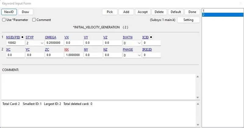
Fig 27: Angular velocity is provided for the blades.
Control cards definition:
- The simulation run time is set to be 10 ms.
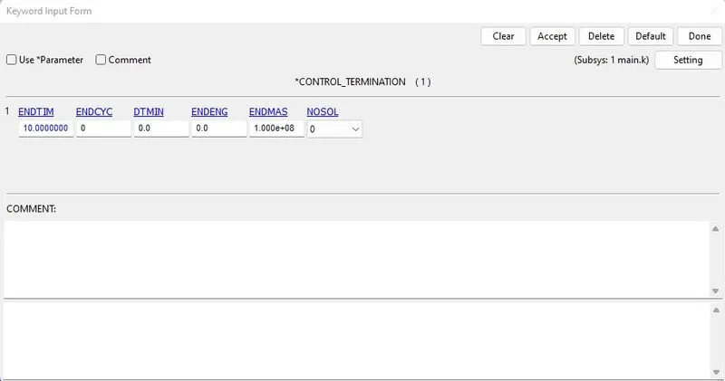
Fig 28: End time is defined for the simulation.
Mass-Scaling:
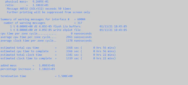
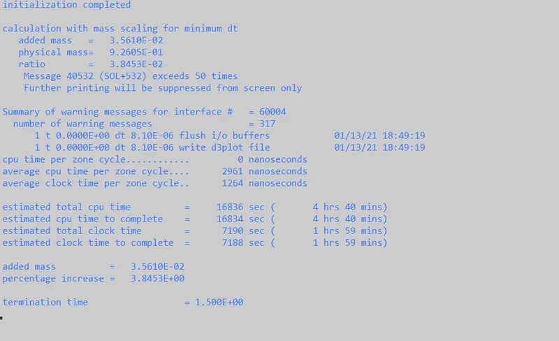
- Since the model is a little bit complex, running this model in a normal system will take more time, so we can use mass scaling to reduce this.
TSSFAC = 0.9, DT2MS = -4.5e-5:
TSSFAC = 0.9, DT2MS = -9E-6:
TSSFAC = 0.9, DT2MS = -9.9E-6:

- For mass scaling after multiple iterations, the time-step card is given with a DT2MS -0.0010 and TSSFAC 0.9.
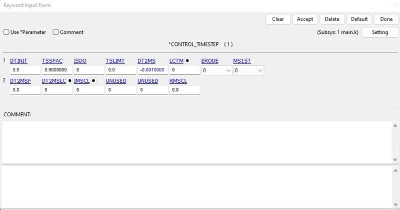
Fig 29: Timestep card is defined with DT2MS and TSSFAC values.
Database:
- Generally, the list of output requests is specified with the Time interval between outputs DT= 0.05 ms for GLSTAT, MATSUM, NODOUT.
- The frequency of the animation file is set to be the Time interval between outputs DT= 0.10 ms.
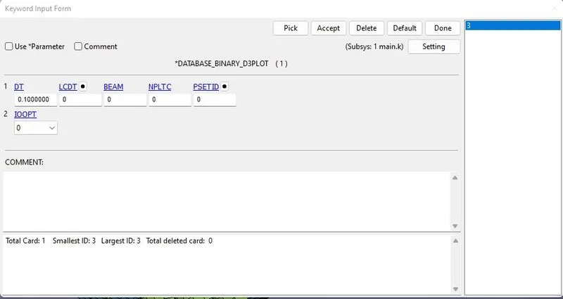
Fig 30: Binary D3Plot card is defined with a time interval.
- The error occurred when the simulation started because the contact definition surface to surface node sets should not be used below.
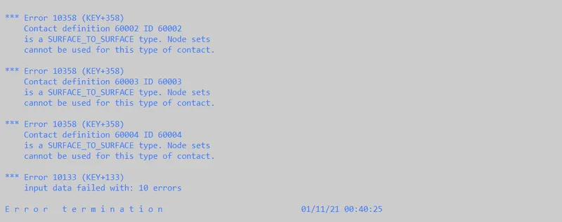
- So instead of node-set id, the part id is used to assign the contacts, and every other thing is good to rerun the model.
Results:
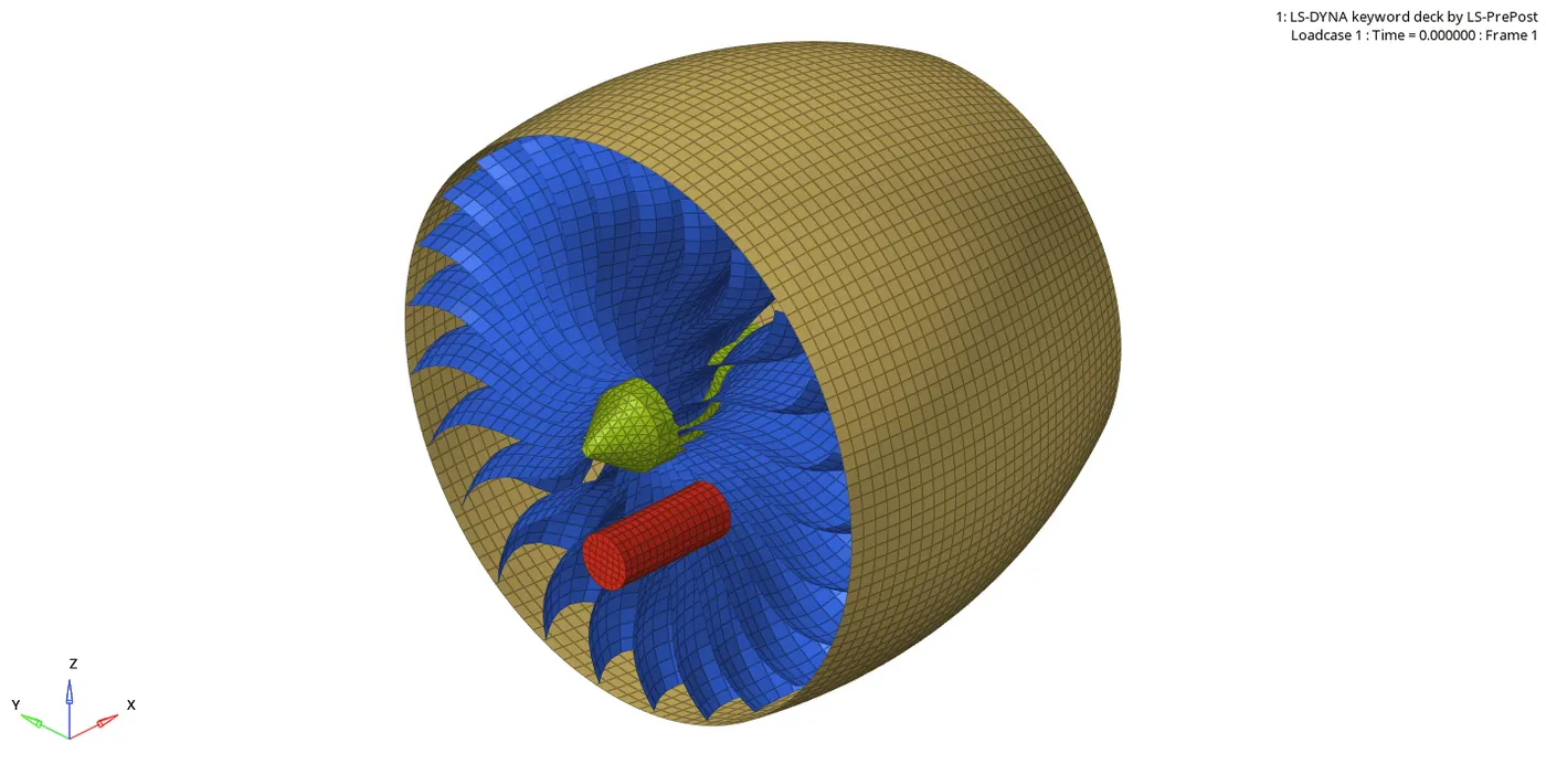
- The above animation shows the bird hitting the blades of the turbine.
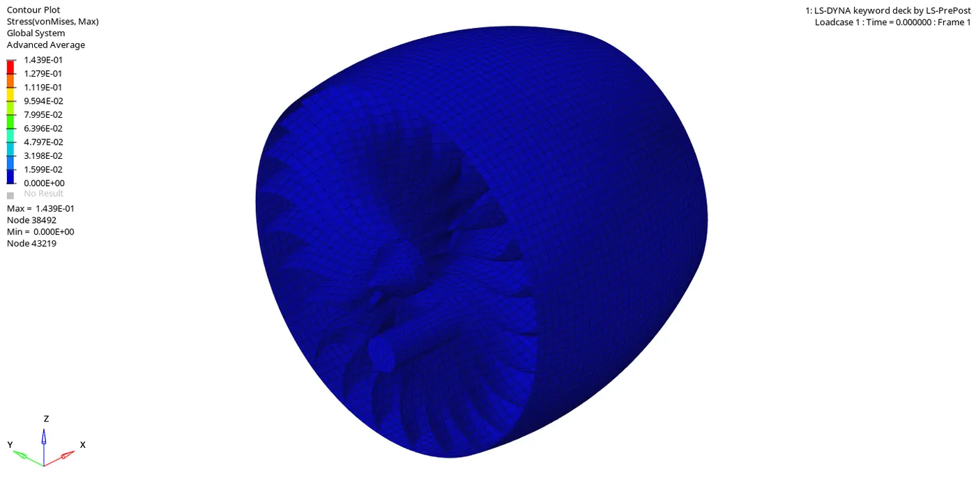
- The above animation shows the von-misses stresses in the blades after the bird hit the blades.
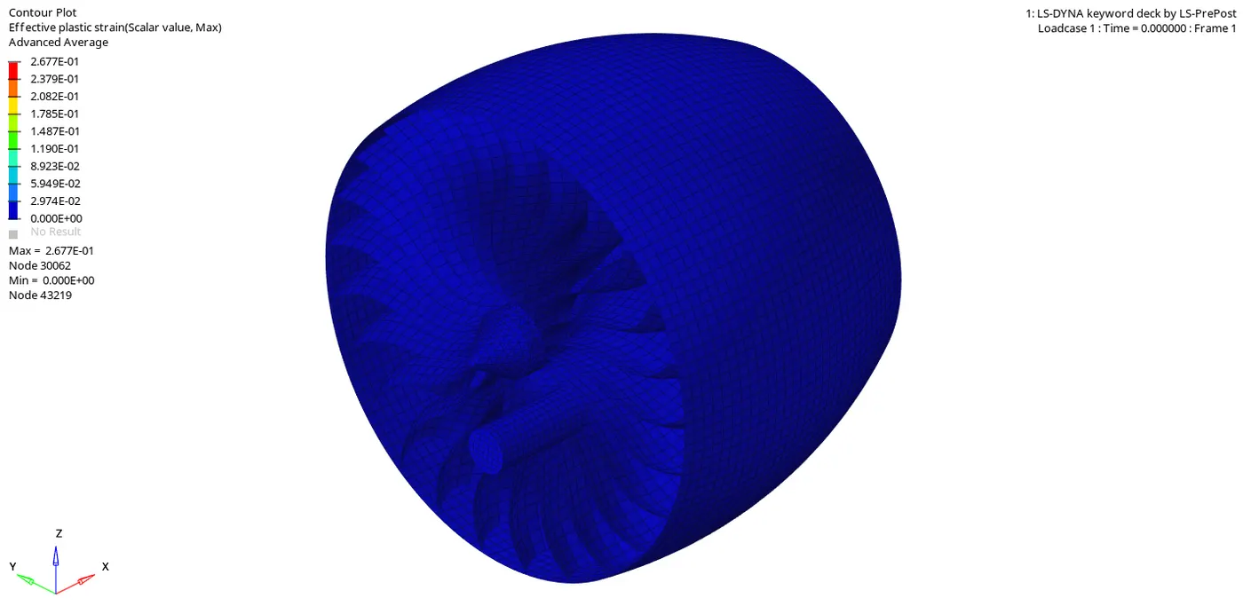
- The above animation shows the effective plastic strain in the blades.
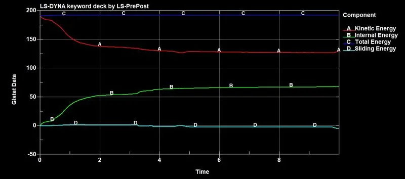
- The above image shows the variation of kinetic energy, internal energy, and total energy. When the bird strikes on the blades, the kinetic energy of the bird decreases, and the internal energy of the bird increases, and total energy remain constant.
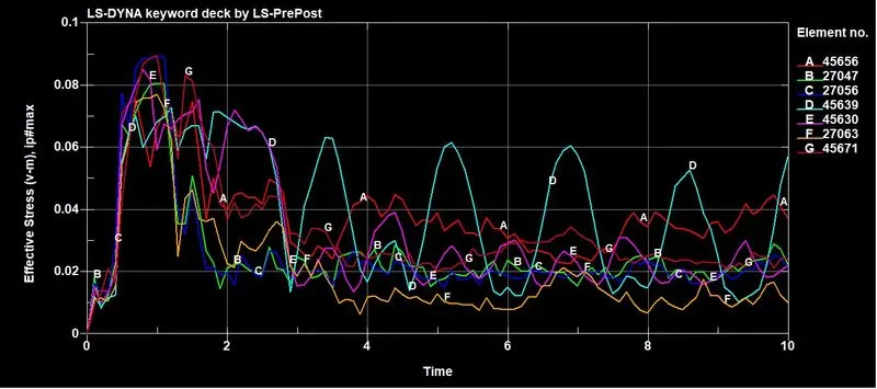
- The above image shows the von misses stress of some of the blade elements, and we can see the variation of stress when the bird hits the blade and reaches its maximum.
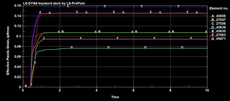
- The above image shows the variation of strain in the blade elements. When the bird hit on the blades, some of the elements at the hit region show high strain, but the strains of each element vary due to the amount of energy observed.
Conclusions:
- The bird strike and aero-engine model are built, and simulation is carried according to the given objective and requirements.
- The result and simulation show that it is almost similar to the real-world scenario.
- All the subsystems were created and included with the Main.k file.
- The simulation is assigned and performed using the mass scaling factor.