Bird Strike - Project - 2
AIM: To perform the simulation of Bird Striking on the Aero-Engine.
PROCEDURE:
- The Aero-Engine model and the Bird model is provided as shown below:
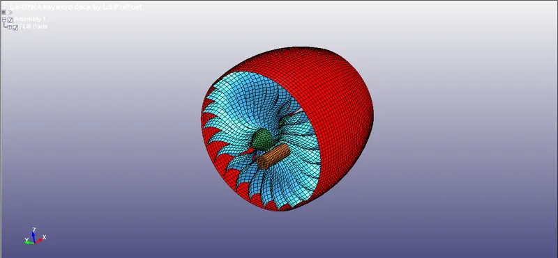
- Now we have to create a different Input files from the same file as shown:
BIRD:
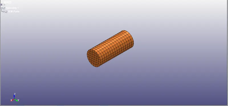
BLADE:
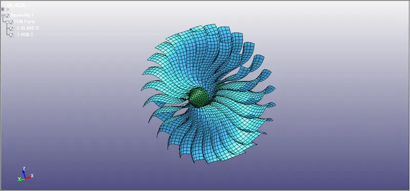
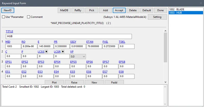
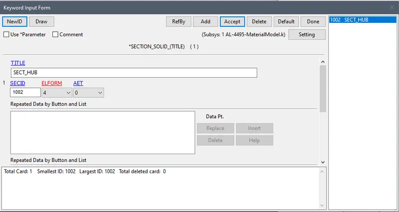
HUB:
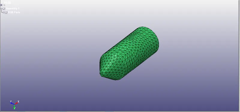
ENGINE CASING:
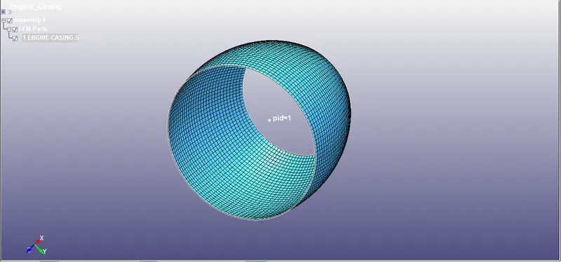
- Now we will create a material and sections for the all component.
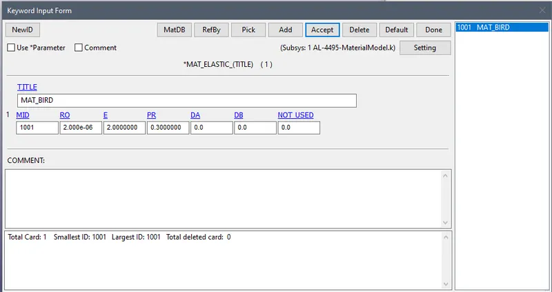
BIRD:
- The Young's Modulus of bird is given as 2000MPa
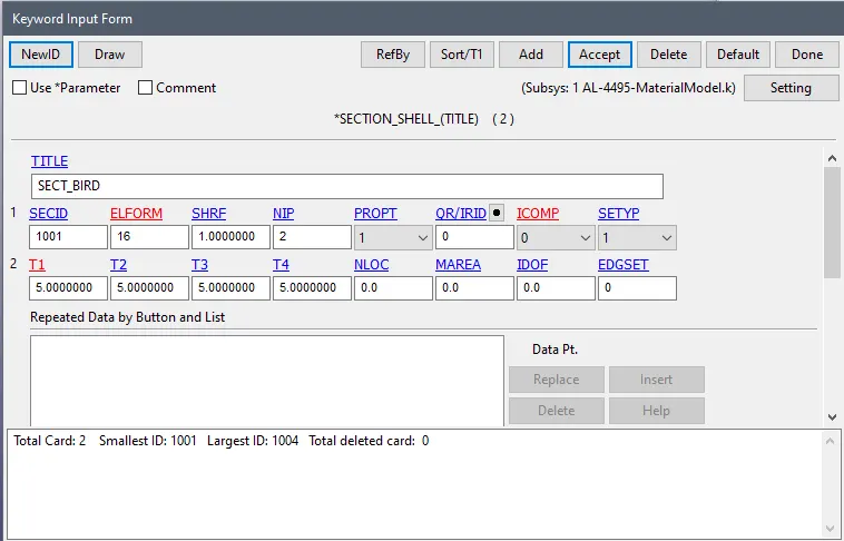
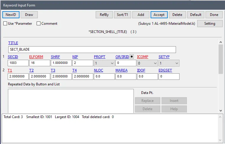
BLADE:
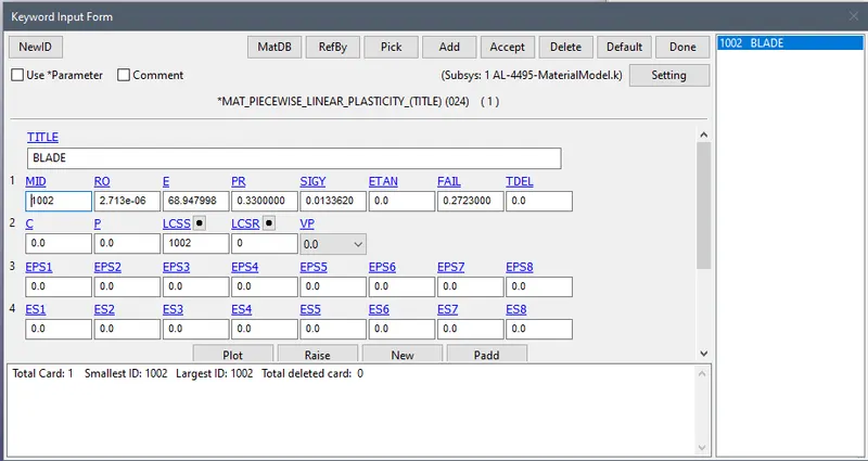
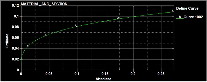
- The curve for the plate is given in the Material file.:
HUB:
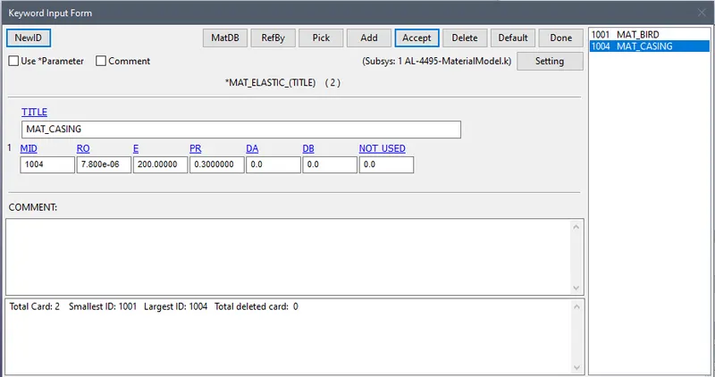
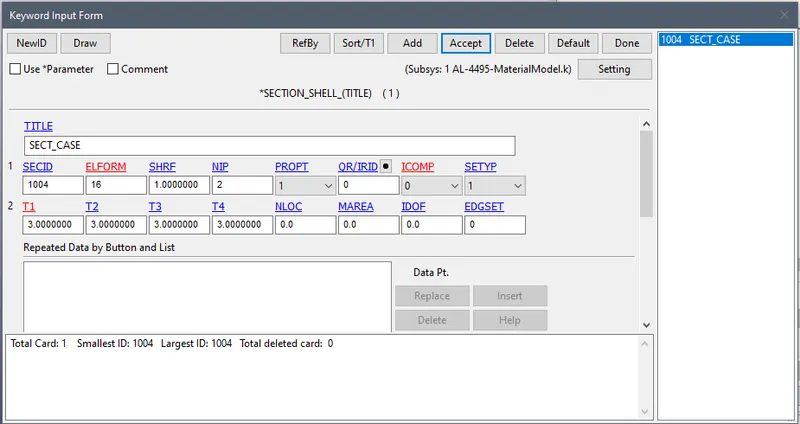
CASING:
- The Young's Modulus of casing is given as 200GPa
- Now we will inlcude all the file in a main file with the help of *INCLUDE keyword. MODEL>KEYWRD>INCLUDE
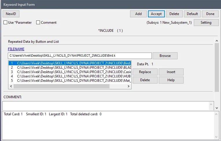
- Now we have included the file next step is to assign the CONTACT to the elements. With MODEL>KEYWRD>CONTACT
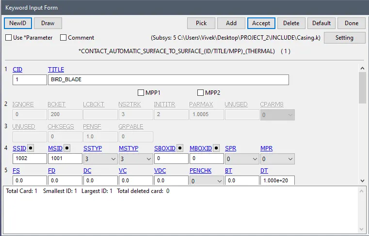
Contact between bird and blades:-
- The bird is strike with the blades, so we create contact between them.
- We create Automatic_surface_to_surface contact between them.
- Here bird as slave and blades as master.
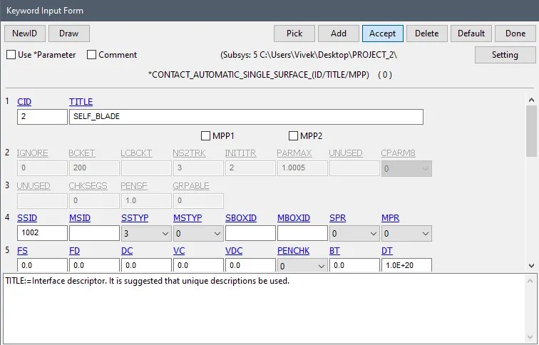
Self contact of blades:-
- After impact chance to blades is broken and collide with each other.
- So we need to create self contact for blades.
- For that go toModel>Keyword>Contact> Automatic_single_surface
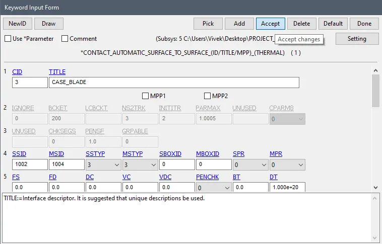
Contact between blades and casing:-
- We create Automatic_surface_to_surface caontact.
- For that go to Model>Keyword>Contact> Automatic_surface_To_Surface
- Here choose blades as slave and casing as master.
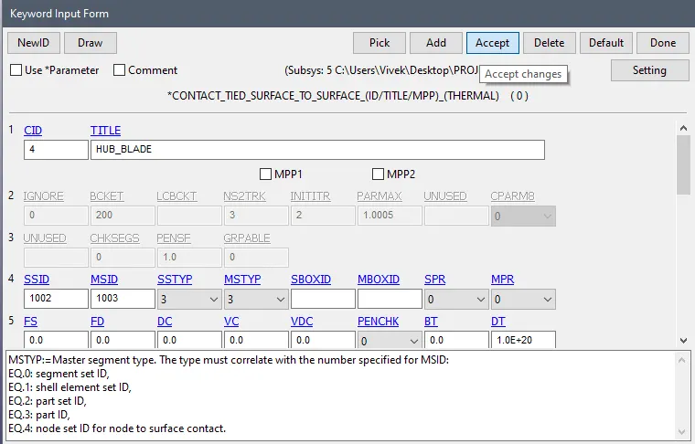
Contact between blades and hub:-
- The hub is modelled with solid elements and blades are modelled with shell elements.
- So we need to create ted contact between them.
- For that go to Model>Keyword>Contact>Tied_surface_To_Surface
- Here choose blades as slave and hub as master.
- Now we will assign the BOUNDRY CONDITIONS to the elements.
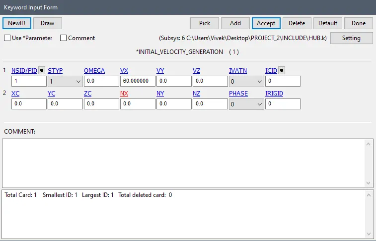
BIRDS:
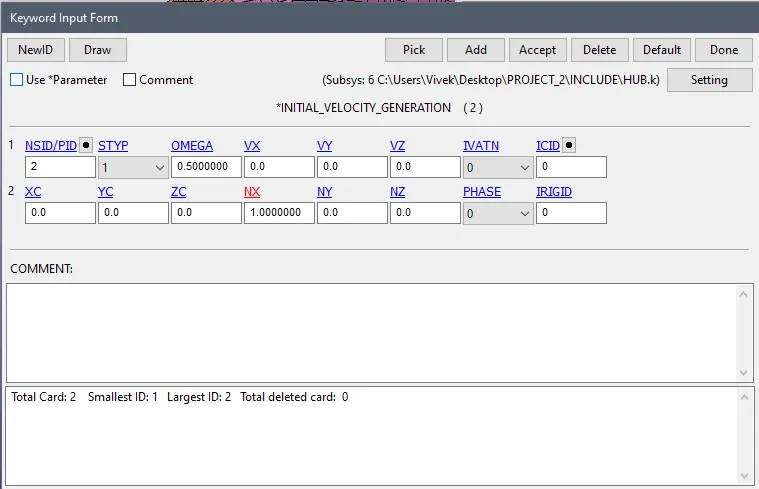
- We will assign the Velocity to the bird along X-axis. Vx=60mm/ms
- For that go to Model >Keyword> Initial> Velocity generation.
BLADE:
- Now for blade we will assign the rotational velocity along X-axis. With the help of same ID card.
SPC
CASING:
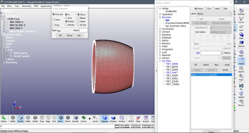
- The Casing is constrained along all the direction.
BLADES:
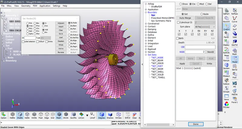
- The blades should be unmoved at the time of impact, so we constrains only x-direction. And also the HUB contrained along the X axis too.
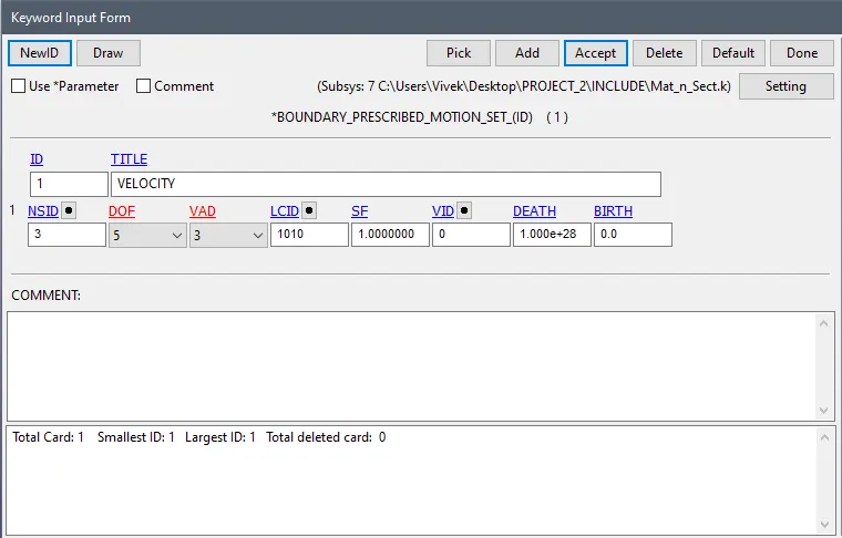
PRESCRIBED MOTION:
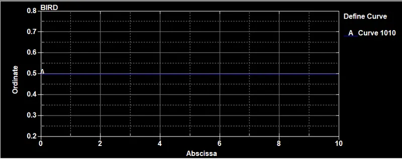
- This keyword is use for maintain constant velocity of the blades and hub during the all over simulation.
- For that first of create the curve.
- For that go to Model> keyword>Define> curve
RENUMBERING:
CONTROL CARD:
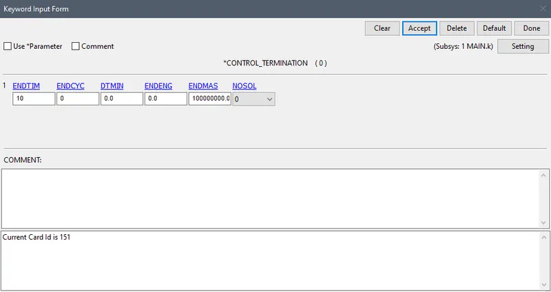
1. TERMINATION:
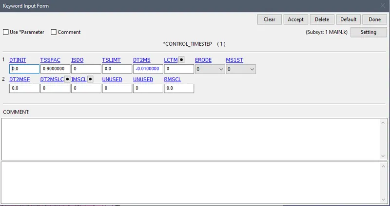
2. TIMESTEP
OUTPUT REQUEST:
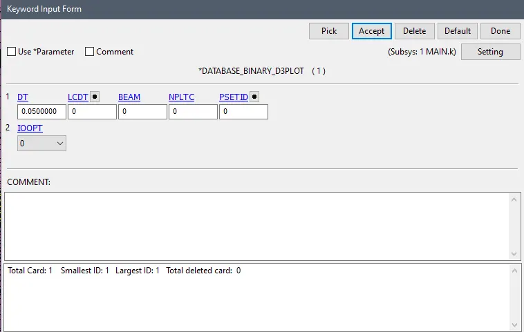
1. D3PLOT:
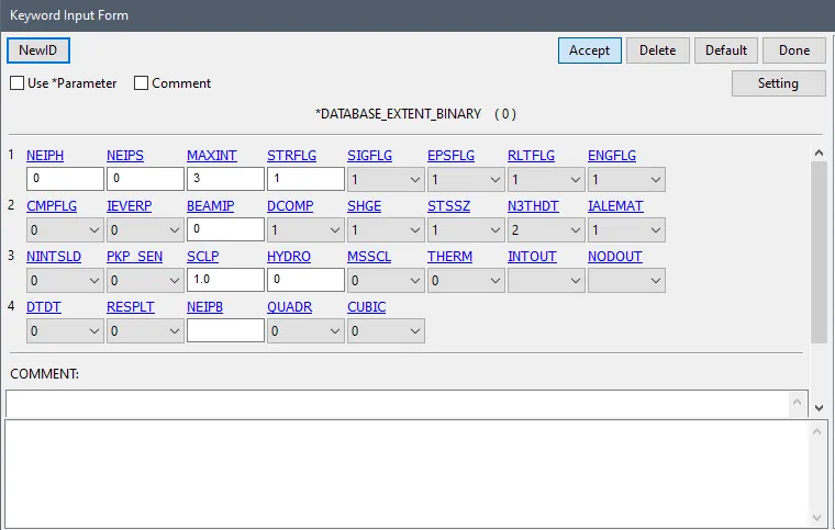
2. EXTENT BINARY
3. ASCII OPTION:
- Select GLSTAT and RCFORCE
- Now save the .k file and run the simulation.
D3PLOT
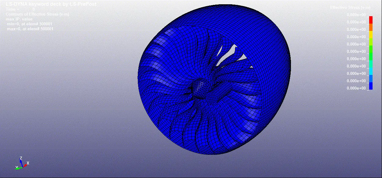
VON-MISSES STRESS
GRAPHS:
ENERGY PLOT:
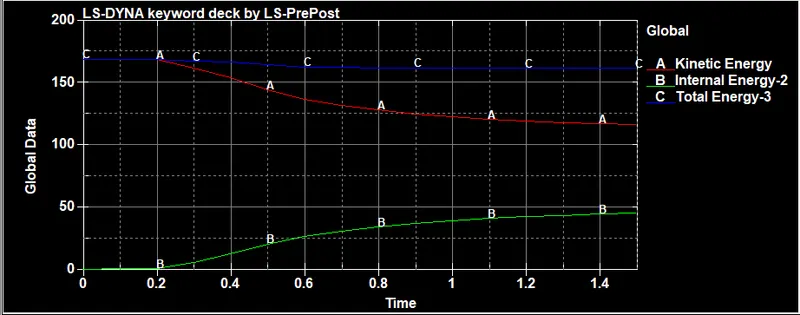
- As shown in the above figure after the bird strikes the kinetic energy decreases which causes an increase in the internal energy of the system
EFFECTIVE PLASTIC STRAIN:
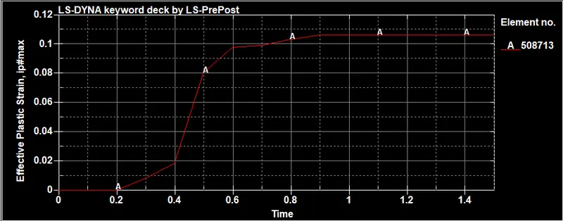
- As seen the Effective plastic strain increases as the bird strike the blade.
- The element is selected form the deformation region of blade
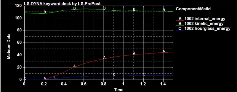
MATSUM DATA
- FOR BLADE:
CONLCUSION:
- The bird impact analysis is performed in LS-DYNA. From post-processing, the severity of the bird impact on the blades is analyzed. There is some permanent deformation in the blade which is impacted with the bird. There is no significant change in global energy.
- Include file is used as per the give instruction.
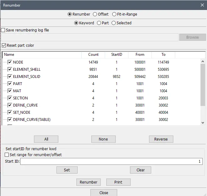
- Renumbering is also done.