Bird Strike - Project - 2
BIRD STRIKE SIMULATION ON AN AERO ENGINE USING LS-DYNA
AIM
To create the simulation of bird strike on the Aero Engine from the given FE model.
Following are the information and conditions required to model the phenomenon
- The blades should rotate at a constant velocity but the casing should remain stationary.
- The cylindrical bird model should travel along its own axis and hit the blades.
- Use elastic material for the bird(2000MPa) and the casing(200GPa).
- The material model for the blades is given.
- The velocity of the engine blades and the birds can be chosen so that blade failure can be seen within a short span of time.
- To follow a consistent numbering approach 100000+ for nodes, 500000+ for elements, and 1000+ for the parts. All other keywords should be numbered within 10000-19999 while following a range for each one.
- The bird, casing and the blades should be in different input files as well as control cards and boundary conditions and there should be one main file referencing all the input files.
- The reference include path should be such that the folder can be copied anywhere and it is able to correctly reference all the file and run the simulation.
Note: The unit system used is kg-mm-ms.
INTRODUCTION
The collision of birds on an aircraft while cruising in the air is called Bird Strike event and it is one of the most dangerous accidents that often occur. Therefore, certification of a bird strike is one of the important processes in aircraft design. In particular, the areas where bird strikes occur a lot are on the front leading edge of the wing, the cowling part of the engine, rotating engine fan blades, the cockpit transparency and the landing gear part. This project is a classic nonlinear transient dynamics problem similar to car crash and mobile drop. While accurate modelling of the problem requires advanced techniques such as SPH, this problem can be solved using generic explicit solver.
PROCEDURE
The given FE model of Aero Engine assembly is opened in LS-PrePost and each part is assigned with section property and saved with ‘.k’ extension. The given FE model consists of parts such as bird, blade, hub and casing.
1. Part Definition keyword files
Bird:
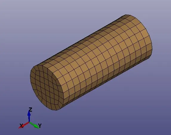
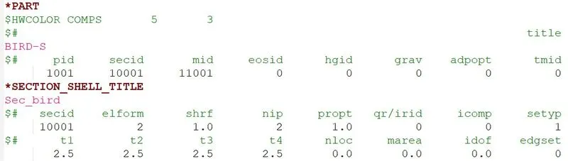
Fig.1 Bird part definition
The given FE model of dummy bird is retained and all other parts are deleted. The part is assigned with section shell properties with ELFORM = 2 and thickness = 2.5 mm. The keyword file is saved with suitable name using ‘.k’ extension
Blade:
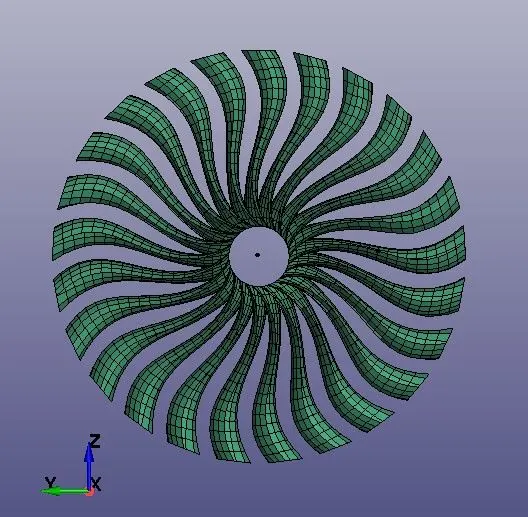
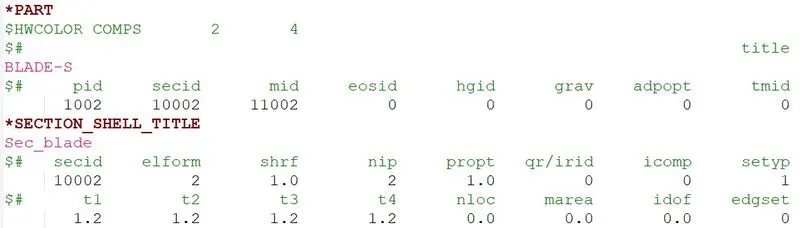
Fig.2 Blade part definition
The given FE model of blade is retained and all other parts are deleted. The part is assigned with section shell properties with ELFORM = 2 and thickness = 1.2 mm. The keyword file is saved with suitable name using ‘.k’ extension
Hub:
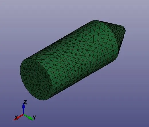
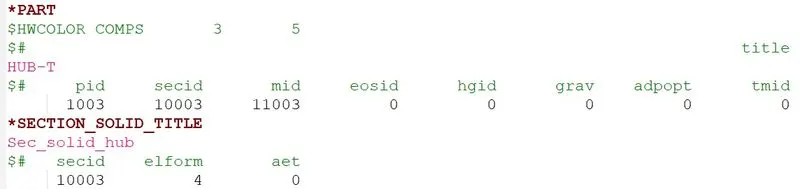
Fig.3 Hub part definition
The given FE model of hub is retained and all other parts are deleted. The part is assigned with section solid properties with ELFORM = 4. The keyword file is saved with suitable name using ‘.k’ extension
Casing:
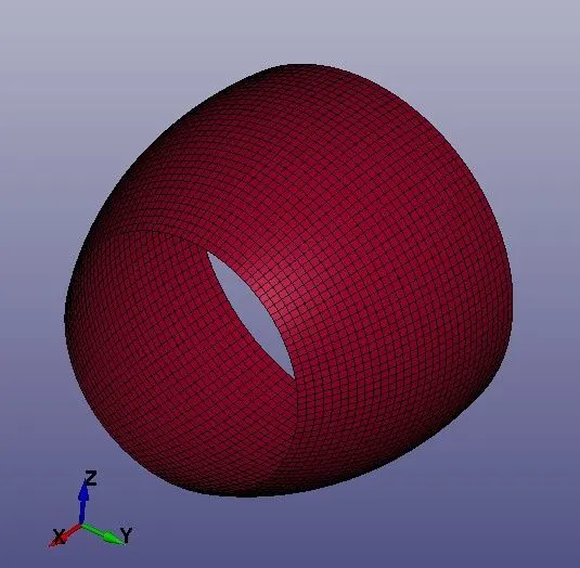
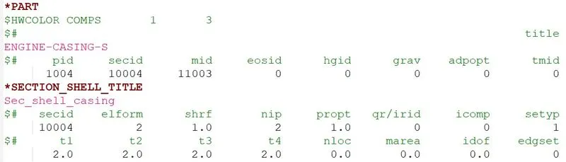
Fig.4 Casing part definition
The given FE model of casing is retained and all other parts are deleted. The part is assigned with section shell properties with ELFORM = 2 and thickness = 2 mm. The keyword file is saved with suitable name using ‘.k’ extension
Material property:
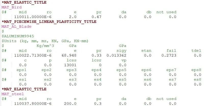
Fig.5 Material property keyword file.
The MAT_ELASTIC material card with mid 11001 is assigned to part with pid 1001 i.e., bird.
The MAT_ELASTIC material card with mid 11003 is assigned to parts with pid 1003 and 1004 i.e., hub and casing.
The MAT_PIECEWISE_LINEAR_PLASTICITY material card with mid 11002 is assigned to part with pid 1002 i.e., blade
The material keyword file is saved with suitable name using ‘.k’ extension.
2. Boundary Condition keyword file
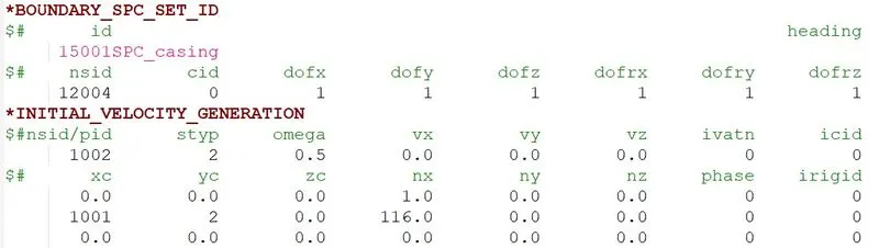
Fig.6 Boundary conditions keyword file.
As stated in the problem the casing has to be stationary, hence the degrees of freedom of nodes in the casing is constrained in all direction.
The velocity of the engine blades and the birds are chosen so that blade failure can be seen within a short span of time. Hence, the angular velocity of blade is assumed as 0.5 rad/ms.
The velocity of bird striking the blade is assumed as 116 mm/ms. The cylindrical bird model is made to travel along its own axis and hit the blades.
The keyword file is saved with suitable name using ‘.k’ extension
3. Contact conditions keyword file
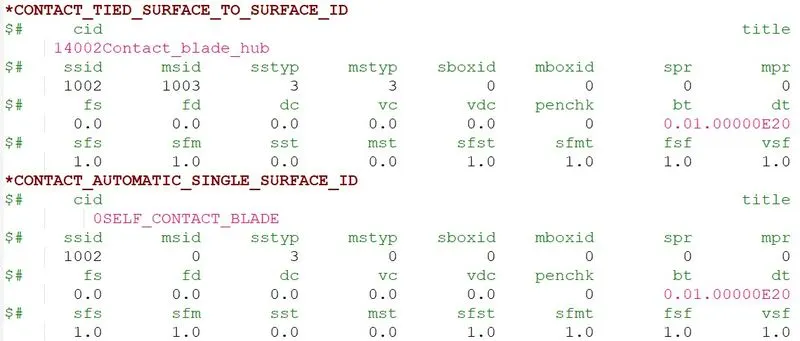
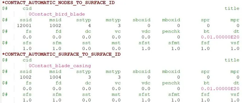
Fig.7 Contact conditions keyword file.
In case of bird impacting the fan blades directly, it is important to assign the proper contact between,
- Bird and fan blades,
- Fan blades and hub,
- Fan blades with other blades,
- Blades with casing.
Contact between bird and fan blades was defined by using nodes to surface contact where bird is the nodes and blades are surface. The impact of the bird with a blade induces reaction loads that counter the rotational forces of the blade thus deforming the blade enough or fracture, portions of the same blade may even come into contact with the remaining blade and casing.
The hub and blade are held together using tied surface to surface contact.
The contact between fan blades with other blades is defined using automatic single surface contact.
The contact between damaged fan blades with casing is defined using automatic surface to surface contact.
The keyword file is saved with suitable name using ‘.k’ extension.
4. Control and Database options keyword file.
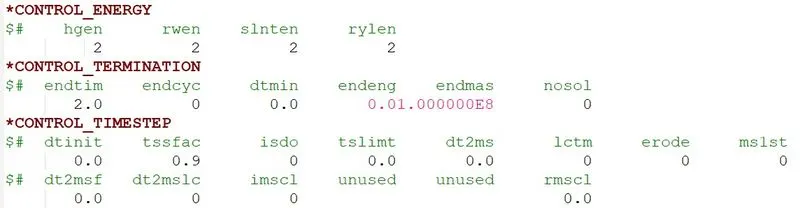
Fig.8 control functions.
The control energy card is used to calculate hourglass energy, stonewall energy, sliding interface energy and Rayleigh energy.
The termination time is set as 2 ms.
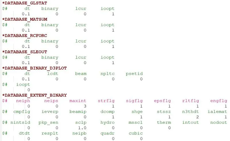
Fig.9 Database options
The time step value of 0.1 ms is given for the BINARY_D3PLOT and in the DATABASE_ASCII option for GLSTAT, MATSUM, RCFORC and SLEOUT
*DATABASE_EXTENT_BINARY card with STRFLG =1, is used to compute the elastic strain in the model.
The keyword file is saved with suitable name using ‘.k’ extension.
5. Main keyword file
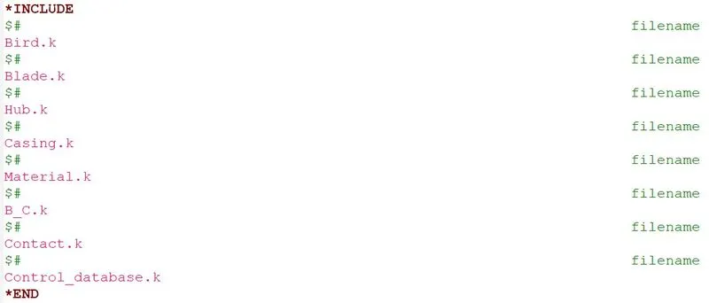
Fig.10 Main keyword file.
The bird, blade, hub, casing, material, boundary condition, contact and control database are in different input files. Hence to reference these input files to one main file, Open LS-PrePost, in the *INCLUDE card type the input keyword file names and insert it and save it as main keyword file with ‘.k’ extension. The main file referencing all the input files is as shown in fig.10. The reference include path is such that the folder can be copied anywhere and it is able to correctly reference all the files and run the simulation.
6. Renumbering Approach
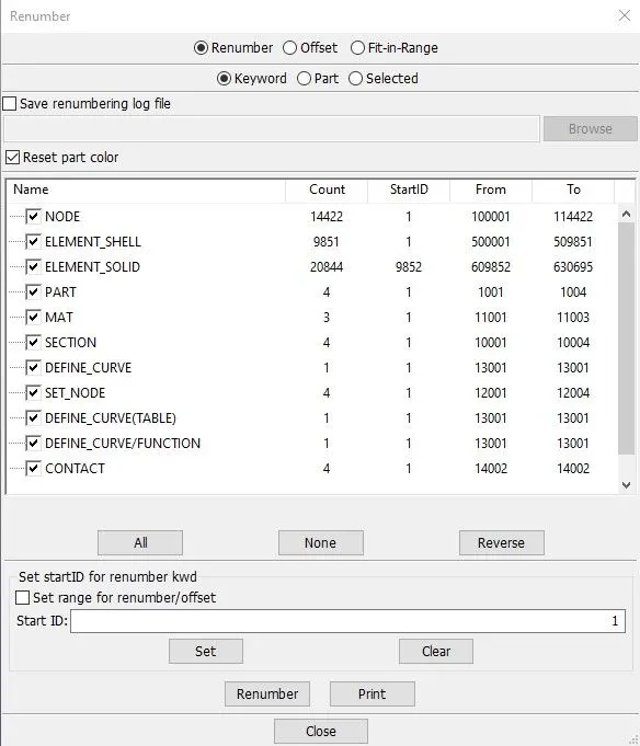
Fig.11 Renumbering.
Renumbering is done by selecting individually the keywords like nodes, elements, parts etc and entering the Start ID value and click Set and Renumber.
A consistent numbering approach is followed i.e., 100000+ for nodes, 500000+ for elements, and 1000+ for the parts. All other keywords are numbered within 10000-19999 while following a range for each one.
These requirements are necessary in a professional setting when dealing with large models and multiple people working with the same model simultaneously.
RESULTS AND DISCUSSIONS
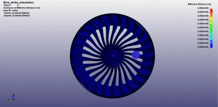
Animation of v-m Stress contour:
Animation of Effective Plastic Strain contour:
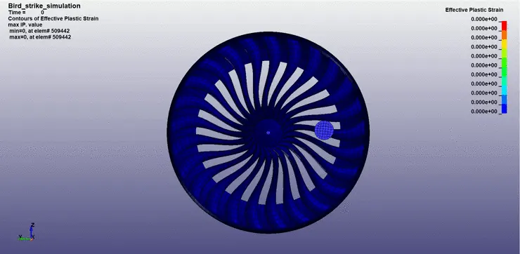
From the simulation, it is observed that the bird striking the blades of the Aero Engine gets damaged. The stress and strain induced in the impacting zone is more such that the blades are broken and gets permanently deformed.
Maximum v-m Stress in the blade:
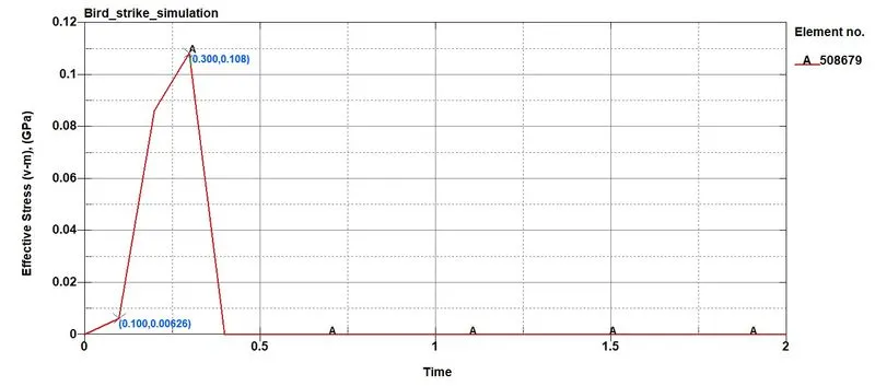
Fig.11 Maximum v-m stress in the blade on element 508679
An element 508679 of the blade at the impact zone is taken to plot the graph of v-m stress. From the graph, it is observed that the v-m stress induced in the element is maximum and reaches to a value of 0.108 GPa which is more than the yield stress value of 0.013362 GPa of the blade material. Hence, the blade is damaged.
Maximum Effective Plastic Strain in the blade:
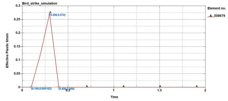
Fig.12 Maximum Effective Plastic Strain in the blade on element 508679.
From the graph, it is observed that the Effective plastic strain induced in the element 508679 is maximum and reaches to a value of 0.272 at time 3 ms during the impact and later dies down Hence, the blade is deformed and broken.
Energy plot
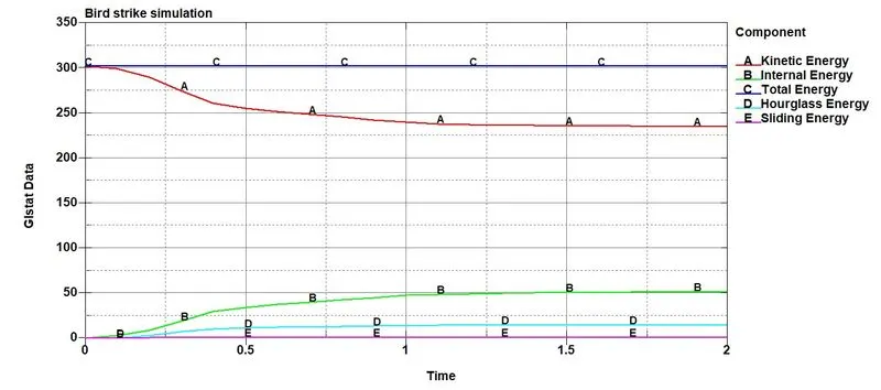
Fig.13 Energy plot graph
From the energy plot graph, it is observed that the kinetic energy is reduced during the time of bird striking the blade of Aero Engine. The internal energy is increased due to the decrease in kinetic energy. The hourglass energy remains low during the entire time of simulation. The total energy remains constant throughout the simulation.
Mass Scaling
i. without mass scaling.

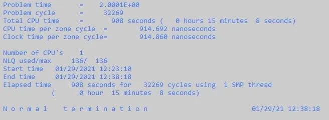
Fig.14 Without mass scaling
The estimated time required to complete the simulation was shown as 40 mins but actually it took only 15 mins to complete the task. Mass scaling approach can be adopted to reduce the runtime.
ii. with mass scaling.
Trial 1: TSSFAC = 0.9 and DT2MS = -2.00E-4
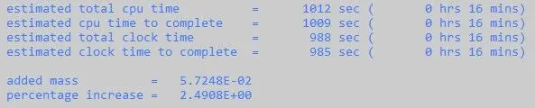
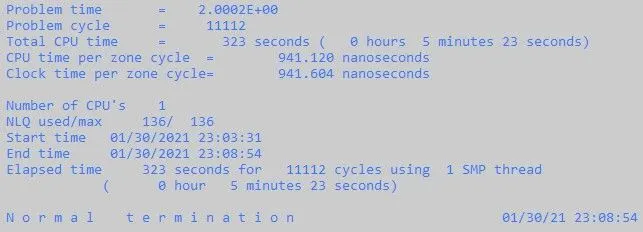
Fig.15 With mass scaling trial 1.
For, DT2MS = -2.00E-4, the estimated clock time to complete the simulation for TSSFAC= 0.9 is 16 mins. The percentage increase in mass is 2.4908%.
Trial 2: TSSFAC = 0.9 and DT2MS = -2.20E-4
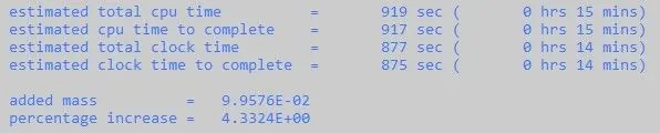
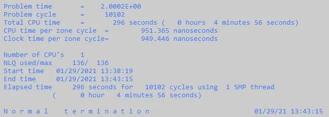
Fig.16 With mass scaling trial 2.
For, DT2MS = -2.20E-4, the estimated clock time to complete the simulation for TSSFAC= 0.9 is 14 mins. The percentage increase in mass is 4.3324%. The runtime has reduced compared to trial 1. The iteration for DT2MS value is continued till the percentage increase in mass is within the limit of 5%.
Trial 3: TSSFAC = 0.9 and DT2MS = -2.50E-4
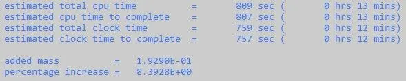
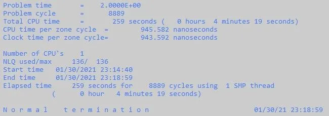
Fig.17 With mass scaling trial 3.
For, DT2MS = -2.50E-4, the estimated clock time to complete the simulation for TSSFAC= 0.9 is 12 mins. The percentage increase in mass is 8.3928%. The runtime has reduced compared to trial 2 but percentage increase in mass is above 5%. Hence, the iteration is stopped.
By considering the hard limit on mass scaling being 5%, the optimized value of DT2MS = -2.20E-4 and TSSFAC= 0.9 with lowest possible runtime required to complete the simulation is 14 mins.
Debugging:
For the initial simulation, following parameters were assumed,
- Poisson’s ratio for bird material = 0.3
- Angular rotational velocity of blade = 1000 RPM = 0.0167 rad/ms
- Initial velocity of bird = 10 mm/ms
- Termination time = 1 ms
- Contact between only bird and blade as well as blade and hub were defined.
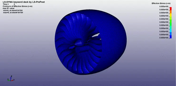
Fig.18 Simulation of bird strike before debugging.
In the simulation, the blade failure couldn’t be seen. Hence to resolve this issue, the keyword file was debugged by running the file for several iterations of assumed parameters with the help of literature survey.
CONCLUSION
- The keyword file to simulate bird strike on an Aero Engine is created by following the necessary conditions and requirements.
- In the simulation, the blades at the impact zone are damaged.
- Mass scaling approach was adopted to reduce the runtime with optimum value of DT2MS = -2.20E-4.
- The initial keyword files were debugged to get a realistic simulation of bird strike phenomenon.
- Learned to create and organise as well as debug the input keyword files similar to a professional setting when dealing with large models and multiple people working with the same model simultaneously.
Google Drive Link: Bird strike simulation