Bird Strike - Project - 2
AIM
The aim of this project is to try to do a somewhat complex simulation which involves the use of most commonly used keywords in LS-DYNA and also try to do the project in a professional manner where a consistent numbering approach is used to number all the nodes, elements etc... and also do the projects in a manner where all the input files and keywords used are separated and included in the main file so that changes can be made easily.
EXPLANATION
This project is a classic non linear transient dynamics problem similar to car crash or a mobile drop. Here we are doing a bird strike on an aero engine. Although accurate modelling of the problem requires advanced techniques like SPH, this problem can be solved using generic explicit solver.
The input files that are given for this project involves a meshed file containing a simple cylindrical model for the bird and contains an aero engine casing alongwith the engine blades and a hub on which the blades are attached. The blades are rotating at a constant velocity while the bird is hitting it. The casing is stationary. The bird model should translate along its axis and hit the blades.
An elastic material with young's modulus of 2000 MPa is used for the bird while the casing is given an elastic material with young's modulus of 200GPa. The material used for the blades is given as an input for this project.
CASE SETUP
A consistent numbering approach is used for numbering nodes, elements, parts, material IDs etc... This is shown in a table below.
| nodes |
1,00,000+ |
| elements | 5,00,000+ |
| parts | 1000+ |
| material ID | 10,000+ |
| section ID | 11,000+ |
| contact ID | 11,500+ |
| partset ID | 13,000+ |
| nodeset ID | 10,500+ |
| define curve | 14,000 |
Here the 1st step is to import the input file containing all the meshed file onto Ls-prepost and renumber the entities according to our numbering approach using the renumber tool. Next ,all the parts are separated and saved as separate keyword files.
All the keywords like control cards, boundary condition, material, section etc. are saved as separate files. These keywords and the meshed parts used are referenced in a main file which is then used for simulation.
An elastic material model *MAT_ELASTIC was used for the bird and the casing. The material of bird was given a density of 2e-06, Young's modulus of 2 and a poissons ratio of 0.3. Here the units used is in kg-mm-ms units. The material for casing was given a density of 7.85e-06, E=200, PR=0.3.*MAT-PIECEWISE_LINEAR_PLASTICITY was given as the material model for the blades. This is already given as an input for the project.
For giving the blades and hub an initial velocity to rotate about its axis we make use of the keyword *INITIAL_VELOCITY_GENERATION. For this we need to create a partset consisting of both hub and the blades. This is done by using *SET_PART keyword. After the partset is created we select STYP as part set ID and give the partset ID of the blades and the hub. The angular velocity was given 0.1 rad/ms. X-axis was given as the axis of rotation.
Using the same *INITIAL_VELOLITY_GENERATION keyword we give the bird a translational velocity to the bird along x-axis. The velocity given is 150 mm/ms. *DATABASE_BINARY_D3PLOT was used to generate the output with DT=0.1. *DATABASE_ASCII option was also used with GLSTAT and MATSUM activated with DT=0.1.
*CONTACT_TIED_NODES_TO_SURFACE was given between the nodes of the blades that touch the hub and the hub itself. *CONTACT_AUTOMATIC_SURFACE_TO_SURFACE was given for the contact between the bird and the blades. This same contact was also used for the contact between the hub and the blades. *CONTACT_AUTOMATIC_SINGLE_SURFACE was used to prevent self penetration of the blades.
*BOUNDARY_SPC_SET was used to constrain the hub in x direction.
*SECTION_SHELL was used to define shell section with thickness T1=1mm. The shell section was applied to the casing, blades and the bird. *SECTION_SOLID was used to define a solid section and it was given to the hub.
*CONTROL_TERMINATION was used to give a termination time of 12ms. Mass scaling was used to speed up the simulation. For this *CONTROL-TIMESTEP was used with at DT2MS = -3e-04. The percentage increase in mass added is around 14% and is less than the 15% limit which is the usual accepted level of mass increase without degrading the quality of the result.
The mass scaling trials is as follows. Without mass scaling the time step size is observed to be 7.69 E-05 with the estimated simulation time being 60 minutes. Next we introduce mass scaling with DT2MS =-1e-04 and the estimated simulation time reduces to about 47 minutes. Also the percentage increase in mass added was 7.77e-04 which is below the 15% added mass limit usually followed. Next ,dt2ms is given as -3E-04. This drastically reduces the simulation time to about 6 minutes. Also the percentage increase in mass added was observed to be 12.3% which is where we would like it to be.
* PART-PART was used to assign the appropriate section and materials to the correct parts. The hub was given a solid section with an elastic material model and the material given to the hub was same as that for the casing.
DEBUGGING PROCESS
Since this was quite a complex project, it was done step by step. The initial process involved getting the blades and hub to rotate. Initially I used *INITIAL_VELOCITY to create the rotation, which was then later corrected by using * INITIAL_VELOCITY_GENERATION instead of *INITIAL_VELOCITY .After making sure that the blades and the hub rotate freely, the bird was given a velocity and the simulation tried again. During this step the bird was given a solid section which resulted in error and was corrected by giving the bird a shell section. Although the bird seemed to look like it was solid, upon inspecting its cross-section it was found to be made of shell.
During this step only *CONTACT_AUTOMATIC_SURFACE_TO_SURFACE was given between the blades and the bird. In this step the blades seem to self-penetrate this was then fixed by giving *CONTACT_AUTOMATIC_ SINGLE_SURFACE to the blades.
Another error that I noticed after giving single surface contact between the blades was that the blades penetrate the hub which is not possible. This was then solved by giving *CONTACT_AUTOMATIC_SURFACE_TO_ SURFACE between the hub and the blades. A high value of angular velocity of the blades also generated high stresses in the blades, which was then solved by giving a moderate value for angular velocity of blades. During one of the simulation it was observed that the hub was moving ,to prevent this *BOUNDARY_SPC_SET was applied to the hub where the freedom to move in x direction was restricted.
RESULTS
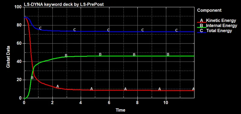
The plot showing the kinectic energy, internal energy and total energy variation of the system is shown below.
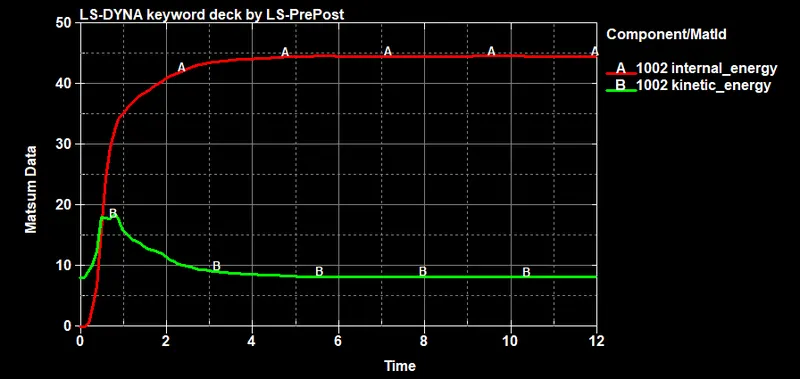
The plot showing the kinectic energy, internal energy and variation of the blades is shown below.
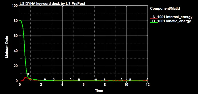
The plot showing the kinectic energy, internal energy variation of the bird is shown below.
Also , from the simulation we find that the maximum effective stress that occour in the system is 99.03 Mpa.
CONCLUSION
From the results it is clear that after the crash kinectic energy of the system is decreased and internal energy is increased. From the energy plot of the bird it is clear that the bird stops moving after the impact.The blades attain more internal energy than initially since the kinectic energy of the bird is used in deformation of the blades.