Bird Strike - Project - 2
Objective:
To simulate the impact of a bird strike on the blades of an aeroplane turbine in LS-Dyna by using the givel models
Methodology:
- The FE model consists of 4 parts that need to be separated and save partwise. The suitable material is created and saved in a subfolder.
- The node number, element number, and part number are assigned as mentioned above. Also, to conclude the final simulation create the main file with the *include file and run the explicit simulation using mass scaling.
THEORY
Bird Strike
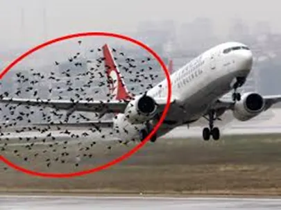
Bird strikes are a major threat to aircraft structures, as a collision with a bird during flight can lead to serious structural damage. Computational methods have been used for more than 30 years for the bird-proof design of such structures, being an efficient tool compared to the expensive physical certification tests with real birds. At the velocities of interest, the bird behaves as a soft body and flows in a fluid-like manner over the target structure, with the high deformations of the spreading material being a major challenge for finite element simulations. Bird strike simulations on aircraft structures have been performed and improved since the late 1970s. A large variety of bird impactor geometries, materials, masses, densities, and modelling methods exists in the literature. There are three established techniques for numerical bird impactor modelling are used: Lagrangian, Eulerian, and SPH. The best approach depends on the specific application, software package, computational resources, and parameter setup.
Model setup
The main file contains the four main parts of the model namely the casing, hub, blade and the bird. They have to be segregated and saved as separate .k files, so that they can be referenced in the main.k include file.
1. Bird
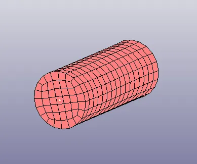
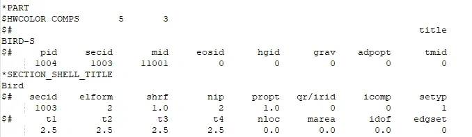
The part representing the bird is defined with shell elements with a thickness of 2.5 mm and ELFORM 2.
2. Blade
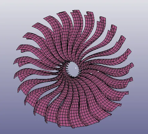
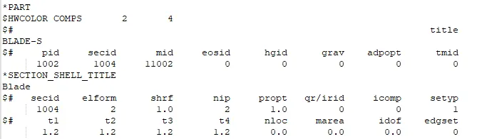
The part representing the bird is defined with shell elements with a thickness of 1.2 mm and ELFORM 2.
3. Hub
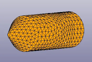
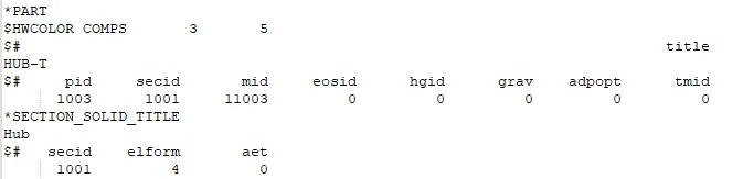
The part representing the bird is defined with solid elements with ELFORM 4.
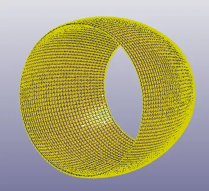
4. Casing
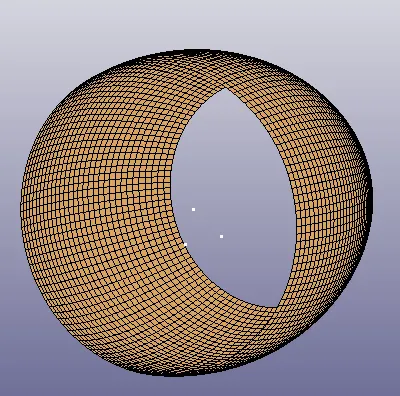
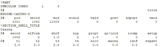
The part representing the bird is defined with shell elements with a thickness of 2.0 mm and ELFORM 2.
Material definition (Material.k file)
The casing and hub are defined with elastic steel material with properties as shown below.

The bird is defined with an elastic material with properties shown below.

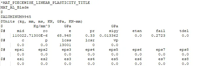
The blades are defined with a piecewise linear plastic material, whose properties are given in the material file.
Boundary conditions (B_C .k file)
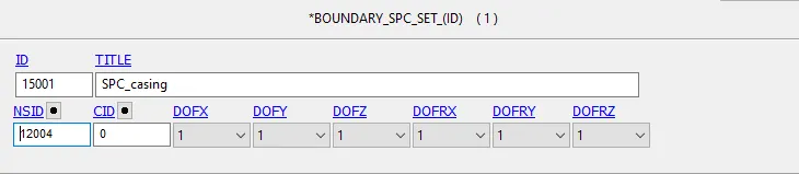
The casing is fixed with SPC on all nodes, constraining motion in all directions.
The blades are given an angular velocity of 0.5 rad/ms, and the velocity of the bird's motion is assumed as 116 mm/ms in the X-direction, as shown below.


Contact definition (Contact . k file)
The following contacts need to be defined in the model.
Contact between
1. Bird and fan blades
2. Fan blades and hub
3. Fan blades (self contact)
4. Blades and casing
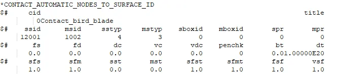
The contact between bird and fan blades is defined using a nodes-surface contact as shown below. (Nodes - bird, surface - blades)
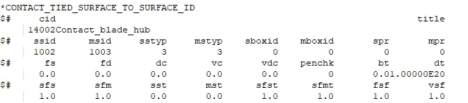
A tied Surface-Surface contact is defined between the blades and the hub.
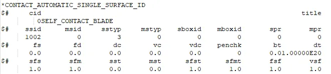
For self-contact of the blades on impact, an automatic single surface contact is used
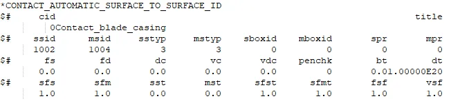
The contact between the damaged fan blades and casing is defined using an automatic surface - surface contact.
Database and control cards (Control_Database.k file)
The following control cards are defined.
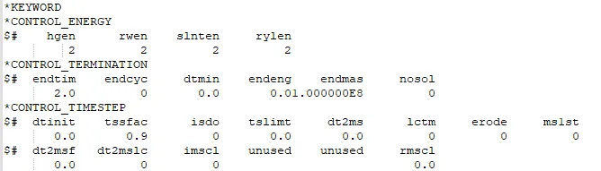
The hourglass energy computation is enabled (HGEN = 2), and the simulation time is 2.0 ms.
The following database cards are defined.
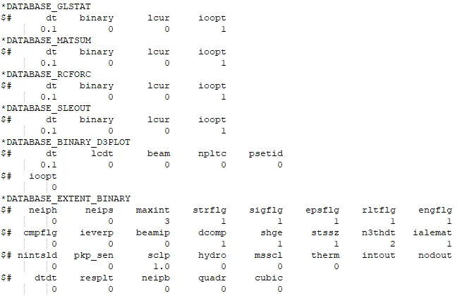
A timestep value of 0.1 ms is given for BINARY_D3PLOT and for the outputs in DATABASE_ASCII.
DATABASE_EXTENT_BINARY card with STRFLG = 1 is used, to compute the strain energy in the model.
Main keyword file (Main.k file)
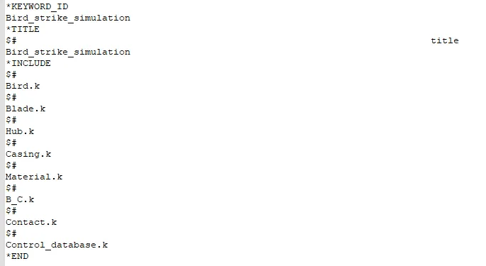
The main file is the include file containing the references to all the individual input (.k files), and the material, boundary and control files, as shown below.
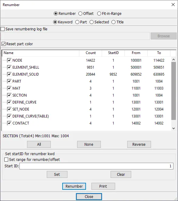
The nodes, elements and the other parts and materials are renumbered in the main file with an uniform convention for ease of use, as shown below.
Results
The model is now ready for simulation and the results can be viewed.
The results of the stress, strain and energy plots can be seen below.
Von mises stress

Effective Plastic strain
Element values
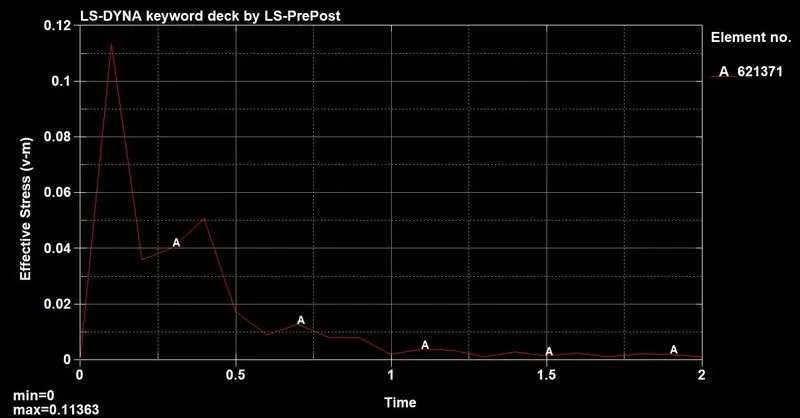
The maximum von mises stress of 0.113 GPa occurs on element 621371. This is higher than the yield stress of 0.0113 GPa of the blades, therefore element failure occurs.
Effective plastic strain
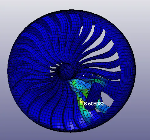
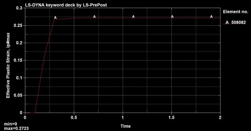
The highest EPS of 0.272 occurs at element number 508082. Since it is in the plastic region, there is permanent deformation in the material ie EPS value stays constant.
Energy plot
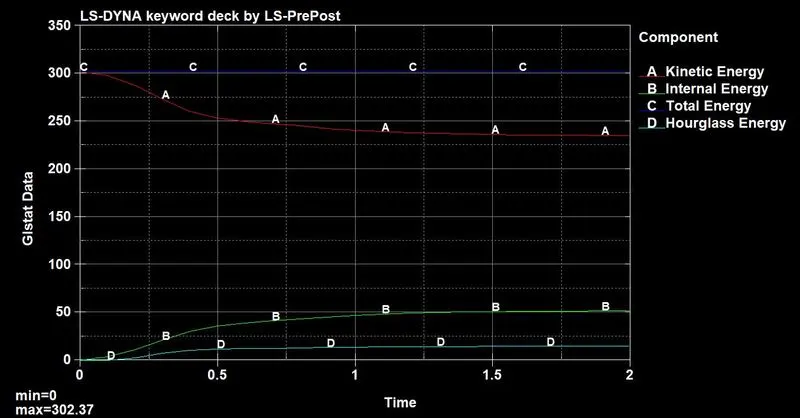
The total energy remains constant throughout the simulation. The internal energy and kinetic energy move towards convergence and the hourglass energy remains low throughout the simulation.
Mass scaling
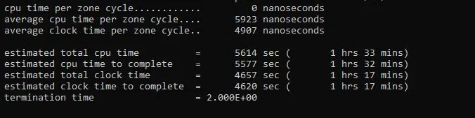
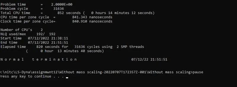
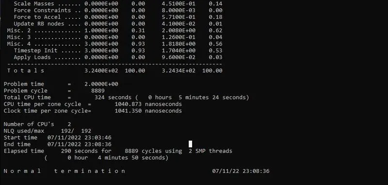
Though the estimated time was 1 hour, the simulation took around 16 minutes to complete, without mass scaling.
Using mass scaling, the run time can be shortened further.
Conclusion
Thus, the simulation of a bird strike on the aeroplane blade is carried out with and without mass scaling, and the results have been discussed.