Side Pole Crash Simulation Challenge
Side Crash Simulation
Aim
To perform side crash analysis on the given Dodge neon Biw model using Hypermesh and Radioss solver.
Setup Request
- Check unit system and either follow [Mg mm s] or [Kg mm ms].
- Create an appropriate interface ,friction 0.2 and recommended parameters.
- Make sure of no penetration and intersections.
- Create a rigid wall with friction 0.1 as per reference model.
- Compare the model weight with the reference model and use added masses to reach the target weight 700kg while getting CG about the required range.
- Initial velocity as shown in the picture.
- Use a model checker to ensure good quality.
- Timestep :0.5 to 0.1 microseconds.
- Run 80ms.
Output requests:
- Sectional force in the cross member.
- The intrusion at B pillar,hinge pillar and fuel tank region.Provide recommendations on what can help to reduce Fuel tank intrusion.
- Peak velocity of the inner node of the door.
Procedure
- The units can be checked by opening the neon_Side_reduced_000.rad file on any text editor.
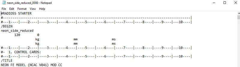
- Since the given units are in Kg,mm and ms,we will follow these units when adding values in hypermesh
- Import the file to hypermesh.
- First, we need to increase the weight of the model to 700Kg while making sure its centre of gravity is in the desired range.
- We can view the cog coordinates using the tools->mass details->mass,cog and inertia.
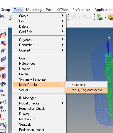
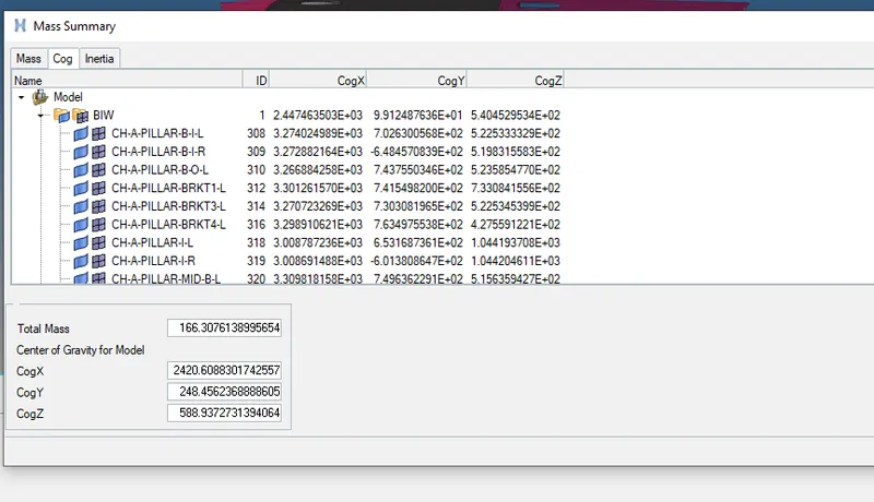
- You can create a node at the given coordinates to visualize the location of the cog.
- Enable the solver browser with view->browsers->hypermes->solver
- Create new mass using admas and use type 1 mass.
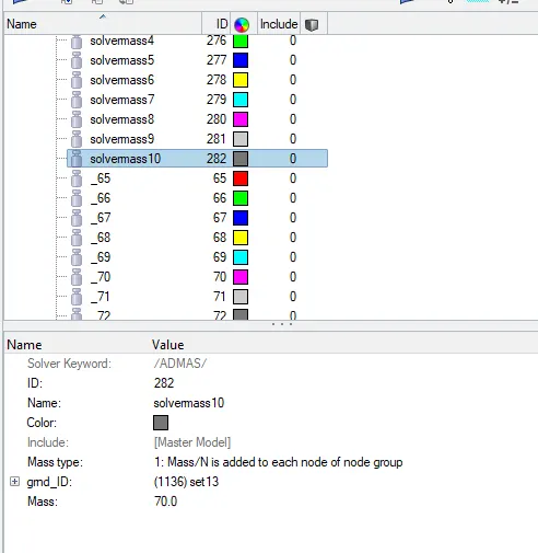
- Create a set of nodes to and assign them in gmd_id.
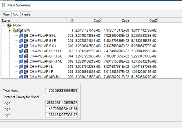
- After mass addition, we check for penetrations and intersections.
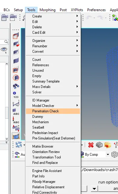
- Go to Tools->penetration check
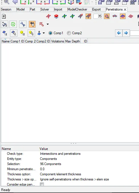
- Select all the components and run the check manager
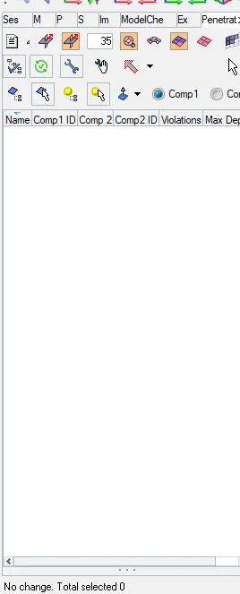
Since there are no penetrations or intersections,it is fine to go to the next step.
Rigid Wall
- We need to create a cylindrical rigid wall to the side of the door.
- In solver browser, create->rwall->cyl
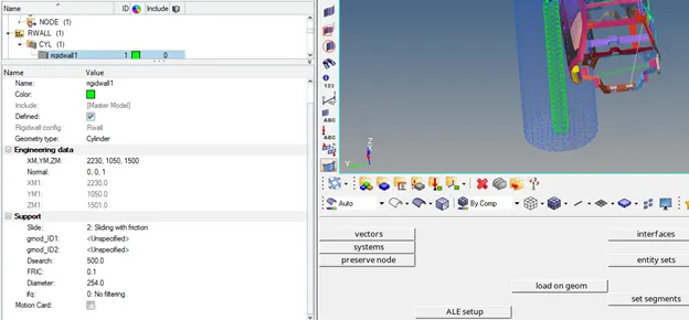
- According to the fmvss standards, https://www.nhtsa.gov/sites/nhtsa.gov/files/tp214p-01.pdf
- The diameter of the cylinder needs to be 254mm.

Interface
- For this simulation, we will be creating a type 7 node to surface interface for self contact.
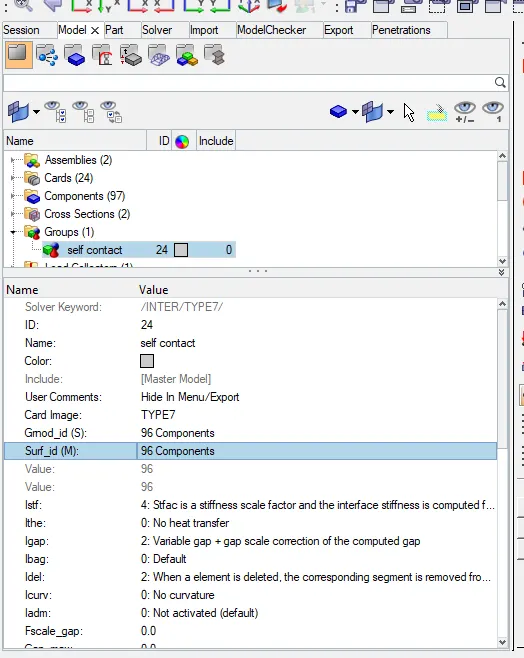
- The recommended values for type 7 contact are
- Igap=2
- Idel=2
- Inacti=6
- Istf=4
- Gapmin=0.5mm
- Iform=0
- Stmin=1Kn/mm
Initial Velocity
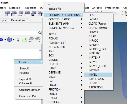
- In solver browser, create->Boundary Conditions->Inivel
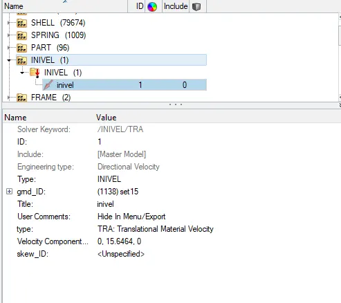
- Create a set consisting of all nodes and add it to gmd_id.
Sections
- We need to create 2 sections at the cross members.
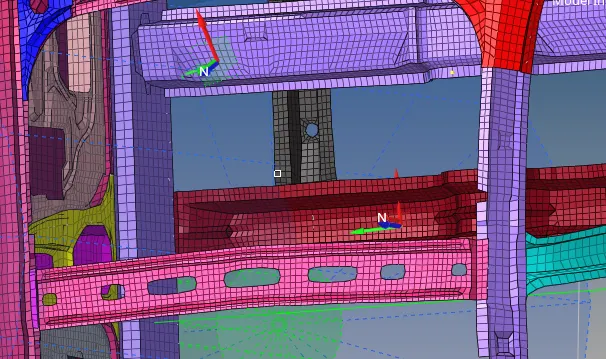
- For each section, it is necessary to create a moving frame at the location.
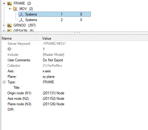
- Choose the nodes such that the resultant is similar to the global axis.
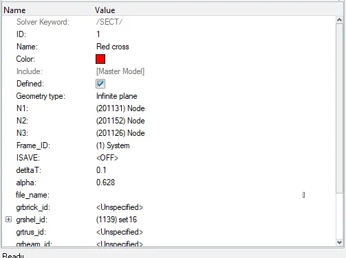
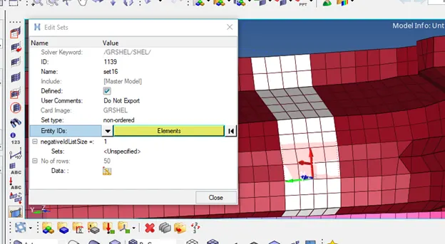
- Create a set of around 3-4 rows of elements for each section.
Intrusions
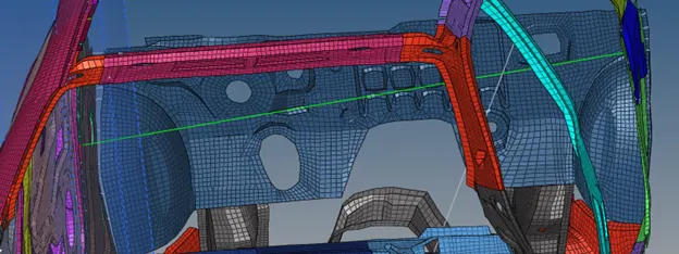
- To measure the intrusions, we will be creating springs between the node and the opposite side of the model.
- The deflection experienced by the spring will indicate the amount of intrusion experienced.
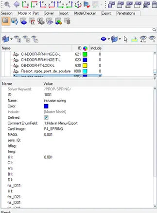
- Create a property card for the spring with a mass of 0.001kg and stiffness of 0.001
Output Files
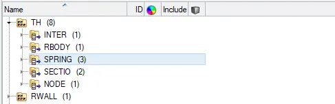
- In the solver browser go to th and create the following output and add the appropriate entities
- For node, the node id is 337773.
Model Checker
- Tools->Model Checker->Radioss Block
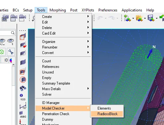
- Run the model checker.
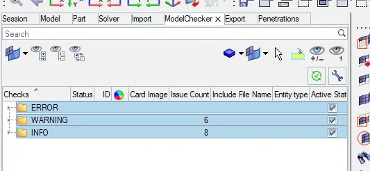
- No errors,only warnings in the model checker
- With this, it is ok to run the model on the radioss solver.
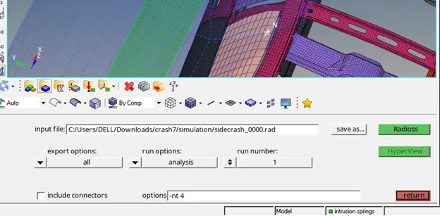
Post Processing
- Open the _0001.out file in notepad , to check energy and mass error
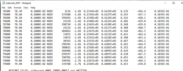
- The energy error and mass error are within acceptable values for further analysis.
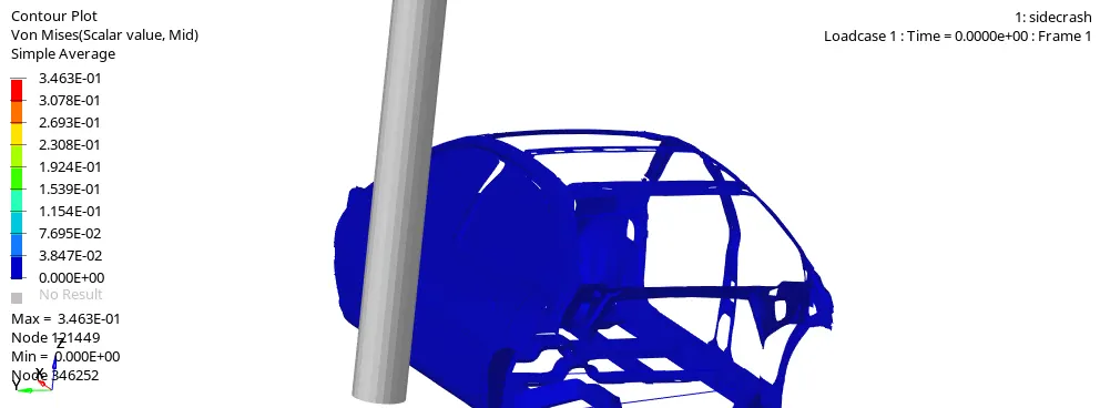
- It can be seen that the b pillar takes initial impact and then transmits the forces to the cross members
Energy Graphs
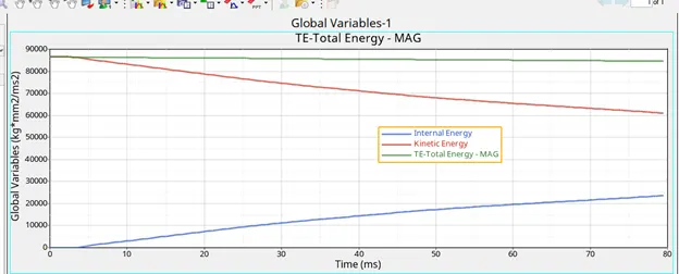
- The kinetic energy at the start is high due to the initial velocity of the model.
- As time passes,the kinetic energy gets converted to internal energy and will eventually reach 0.
- The total energy of the system is almost constant at 84595 kg*mm/ms2
- It decreases a bit due to the energy loss which we can see in energy error.
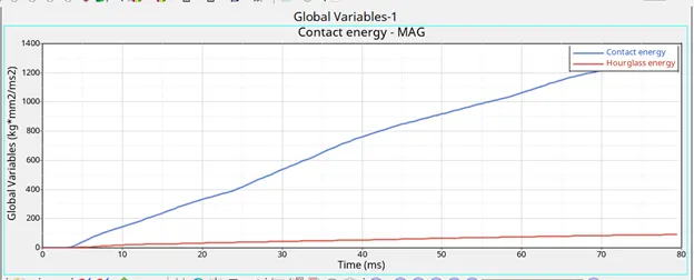
- There is some hourglass energy due to the use of reduced integrated QEPH elements.
- Contact energy is the energy applied by the system to resist penetration of elements
- As the time progresses,due to larger deformations there are more elements in contact with each other, hence more contact energy to resist penetrations.
Rigid wall
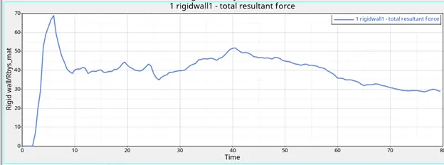
- The rigid wall forces are 0 till the car collides with thte rigid wall after which they spike to 68.90kN.
- After this spike the force decreases to around 40kN.
- After around 25ms,it starts increasing by a bit.This is because,due to larger deformations, more elements come in contact with the rigid wall thus leading to minor spikes in the rigid wall forces
Sectional Forces
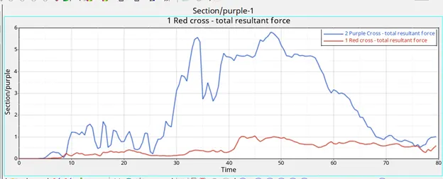
- It can be seen that the force distribution from the b pillar to the cross members is uneven
- This can be because the centre of gravity slightly favours the b pillars cross member
- It can also be because it is closer to the b pillar in comparison to the other cross beam.
- This leads to it having a much higher peak force of 5.8kN in comparison to the 1.05kN of the driver cross beam.
- The cross members along with the b-pillar,doorbar and support and,door outer and rocker are majorly involved to control and reduce deformations
Peak Velocity at Node 337773
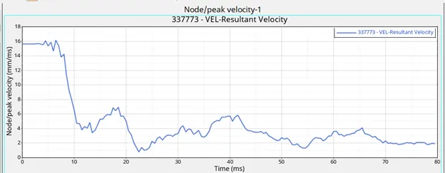
- The velocity peaks at 16.16mm/ms shortly after the crash.
- After this there is a huge drop in velocity,with minor spikes which may be due to the larger deformations that occur due to inertia
- It is important to know this , as during a crash the inner portion of the door might deform excessively and injure passengers
Intrusions
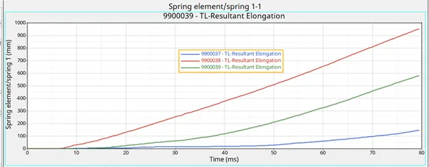
- The red line is the intrusion at the B pillar which peaks at 953 mm and continues to increase.
- The blue line is the intrusion at the fuel tank region which peaks at 150mm.This is the minimum intrusion that is experienced in comparison to the other 2 points
- The blue line is the intrusion at the hinge pillar which peaks at 581mm.
- These intrusions can be reduced by using a stronger material like composites so that the weight increase can be minimized
- An alternative will be to add another crossbeam but the increase to cost and weight can be significant.
Result and conclusion
- The given fe model was set up for side crash analysis and the desired output blocks were created
- The cross members play an important role in force absorption and distribution
- Using a stronger material for them or by adding more cross beams to reinforce the region, it can be possible to further decrease the intrusions at these points
- However it should be noted that such changes can make significant difference in the weight and cost of manufacturing the model.
- Another option is to strengthen the B pillar as it is the initial point of impact.