Assignment 7-Side Pole Crash Simulation Challenge
Import the model in Radioss -
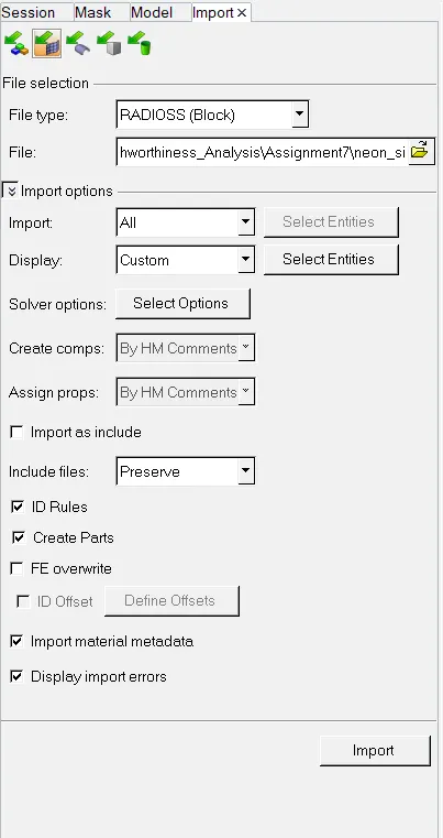
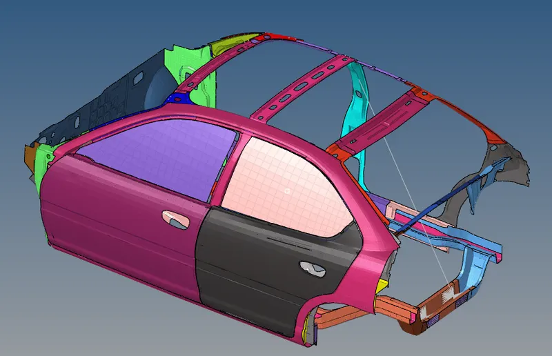
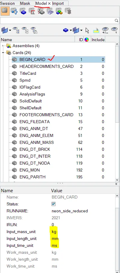
Check for unit system : Go to Model browser - Begin_Card
Or we can open the neon_side_reduced_0000.rad file and check.
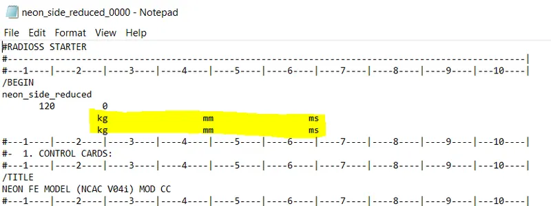
Now Goto Hypercrash - and Import the model. Making sure the Unit system is same.(Kg mm ms)
Start the Hypercrash application from Hypermesh - Application tool.
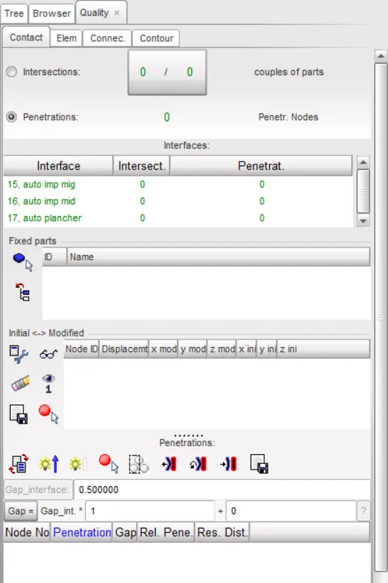
Check for Peneteration and Intersection.
Peneteration is defined as overlap of a material thickness of shell elements. Intersection is defined as element that actually passes through one another.All models should be checked for peneteration and intersection and should be dpeneterated to ensure the integrity of model.Peneteration adversly affect the result and should be removed.
To check this Goto - Quality - Check all solver contact interfaces-select parts -check peneteration.
There are no peneteration or Intersections present in the model.
Compare the model weight with the referance model and use added masses to reach target weight 700kg while getting CG about the required range.
Adding Masses :In order to maintain the CG center of gravity of a car we have to add masses beacuse in the given model there are so many parts are missing becuase of the node limit in student edition of Hypercrash.
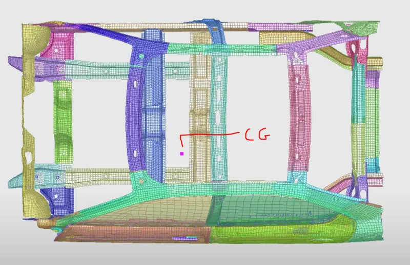
To Check CG goto - Menu - mass - balancing - show CG.
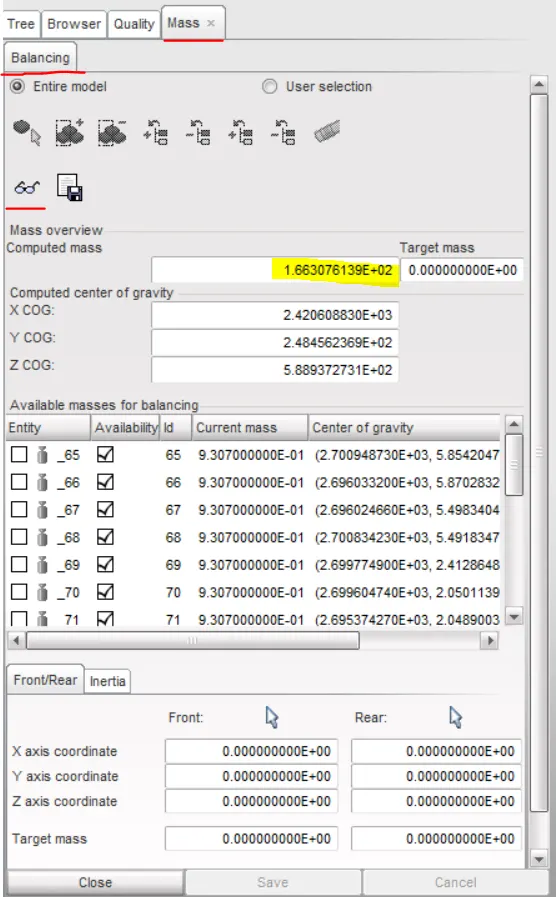
Initial CG Position is given in below image.
Inorder to bring CG to a required position we need to add masses.
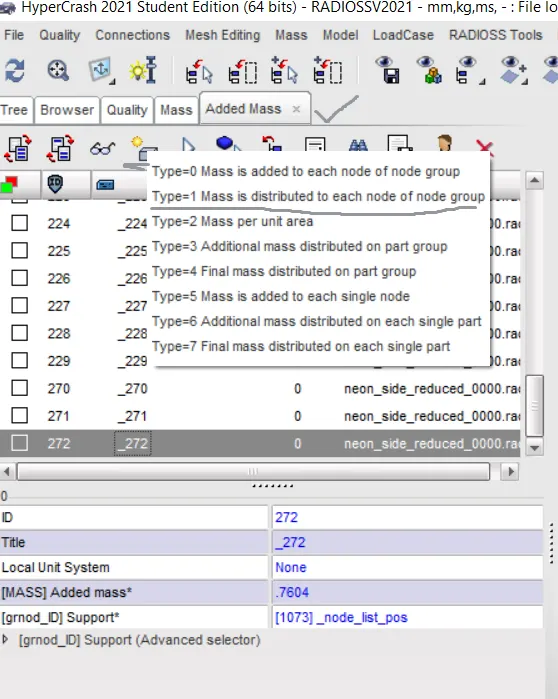
Masses has been added to different parts to achieve CG and total weight of the vehicle i.e 700kg.
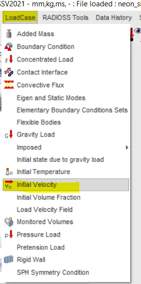
Apply Initial Velocity.
To add initial velocity goto - Loadcases - Initial velocity
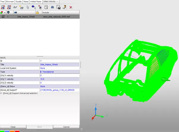
For Grnod_id -select all the nodes in model. The required velocity is 35mph converting that to m/s i.e 15.6m/s as the units are set to mm/ms and the velocity is along Y axis.
Export the Radioss radioss file from Hypercrash to Hypermesh to do the rest setup.
Creating Contact Interface -
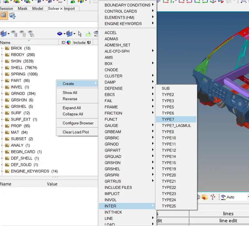
Creating Self Contact - We will create TYPE7 contact for all the components of the model as it is self impacting.
The interface TYPE7 is a multi usage impact interface modeling contact between a master surface and a group od slave node.
First we delete all existing interfaces.
Goto solver browser - Inter - delete all interfaces.
Now create a new Interface.
Goto solver browser - right click - create - contact - rename it - select the slave node and master component - enter TYPE7 recomended properties.
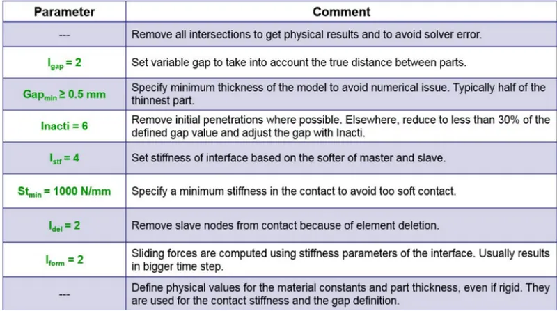
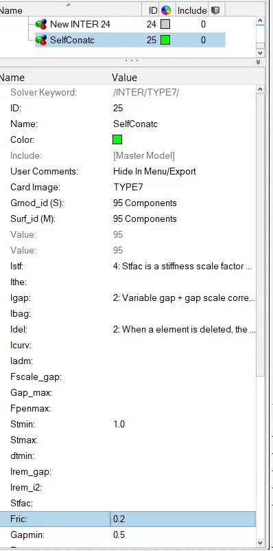
To check that TYPE7 Contact properties has been applied right click on contact and review.
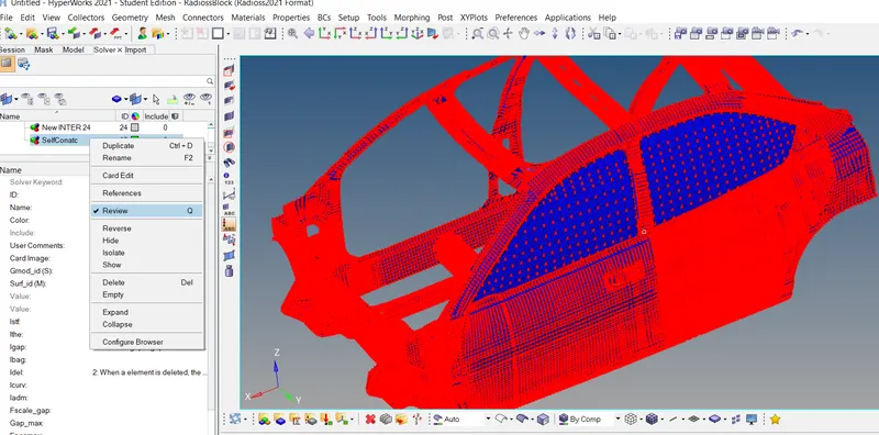
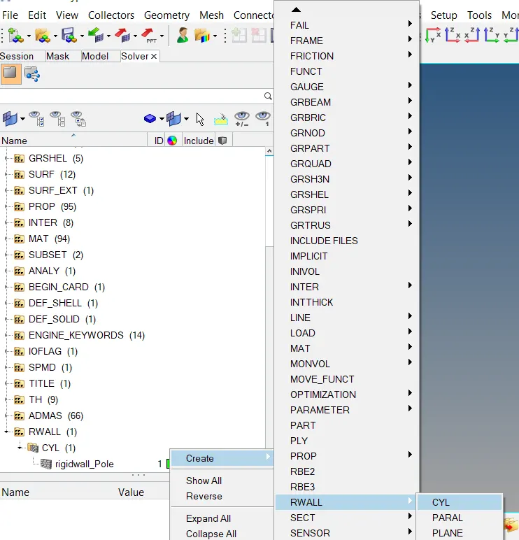
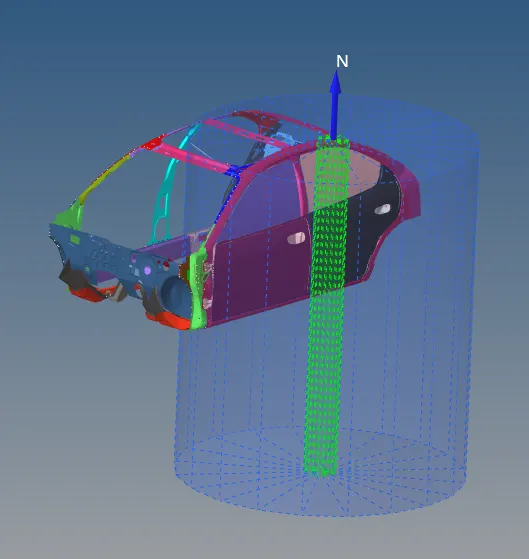
Creating Rigid wall Cyclinder.
To create a rigid wall Goto- Solver Browser - right click - RWALL- CYC.
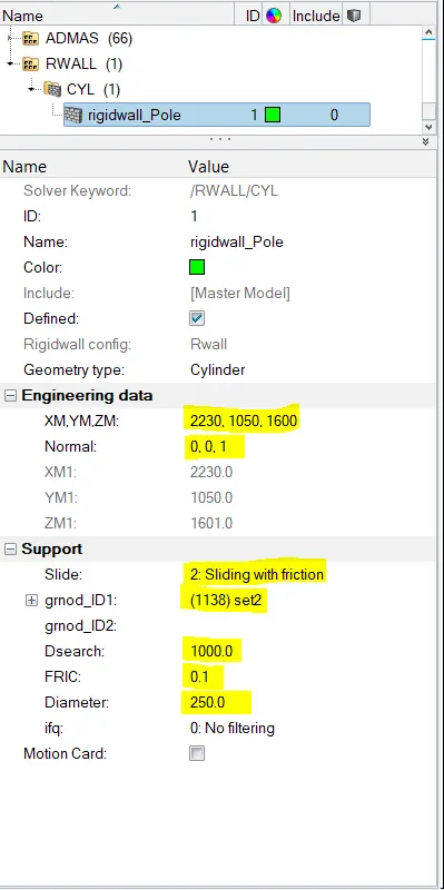
In the Rwall Panel we provide the XYZ co-ordinates for Poles by selecting the node on side door and the offset the node slightly.
Then provide normal direction to the pole as Z-axis = 1 and select grnod = right click create set and select all nodes.
Provide Friction value, Dsearch, Diameter(Pole dia).
Creating Cross Section:
Before Creating cross section we have to create Frame - which is moving frame (Local Axis). We have to align Local Axis to Global Axis.
For Crating Frame Goto- Solver Browser - Right click - Create - Frame -Mov
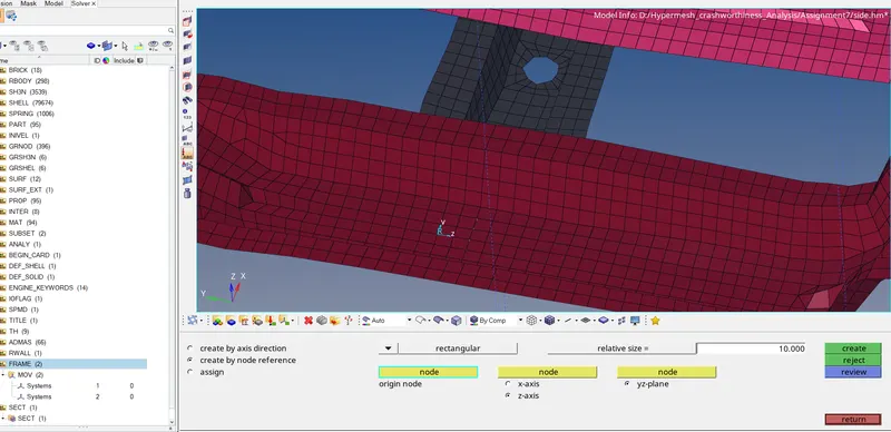
Now Create Cross Section.
Goto -Solver Browser - right click - Sect.
Select the Frame ID that was created and Grshell - create new set - select elements to define section.
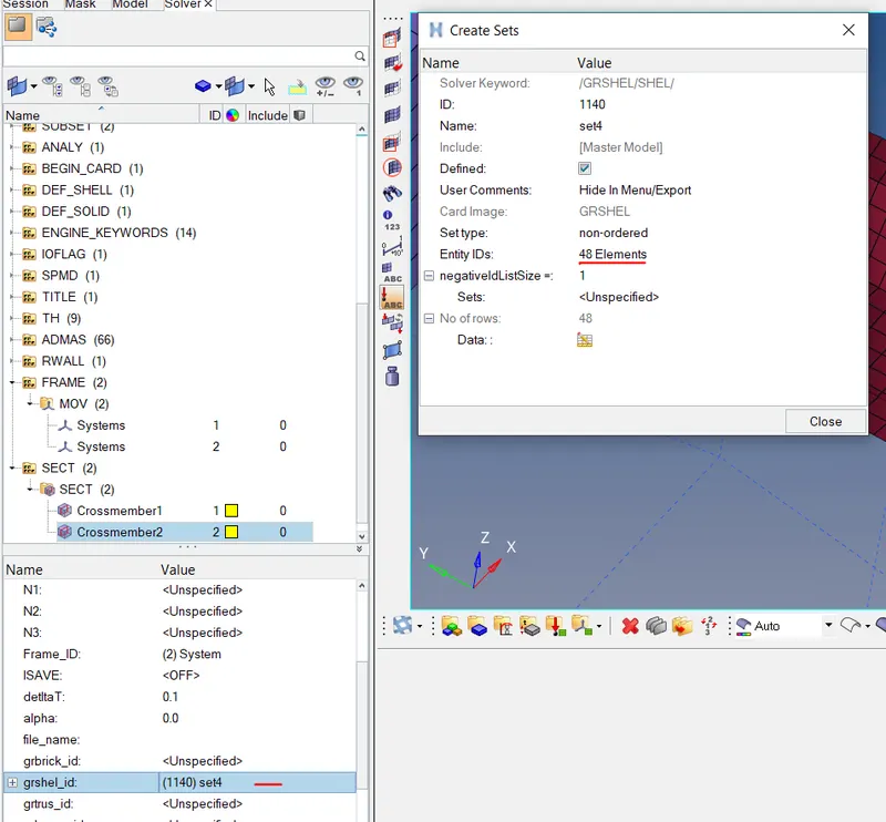
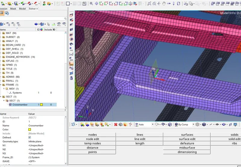
Requesting Output file for cross section created.
After creating Section we will request the result in TH(Time History). For this we goto Output block in Model Browser. Then right click and create a new output block.Under Entity ID we will select the cross section that was created and we will be able to measure sectional forces passing through the cross memebers by creating plotting graphs.
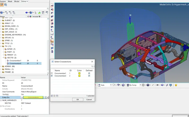
Intrusion :
To find the results at B pillar, Hinge Pillar and fuel tank we need to create Spring between Left and right B pillar, Hinge Pillar and Fuel tank.
Goto- 1D - Spring -Spring2 and select the nodes in left and right parts of each.
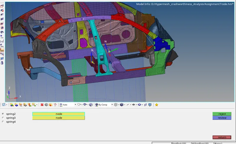
Creating Property card for Spring elements.
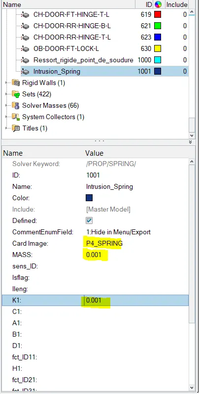
Goto - Model Browser rightclick - create - Property.
Set Card Image as P4 - Spring mass = 0.001 stiffness = 0.001.
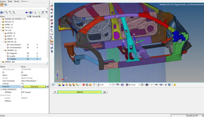
Requesting TH file for Spring elements.
Goto Solver browser -right click - TH - Spring & Assign Entity Id = Spring elements created from the list
Peak velocity of inner node of the door.
To find the Peak Velocity at the inner node of the Door we will have to create the moving frame at node Location.
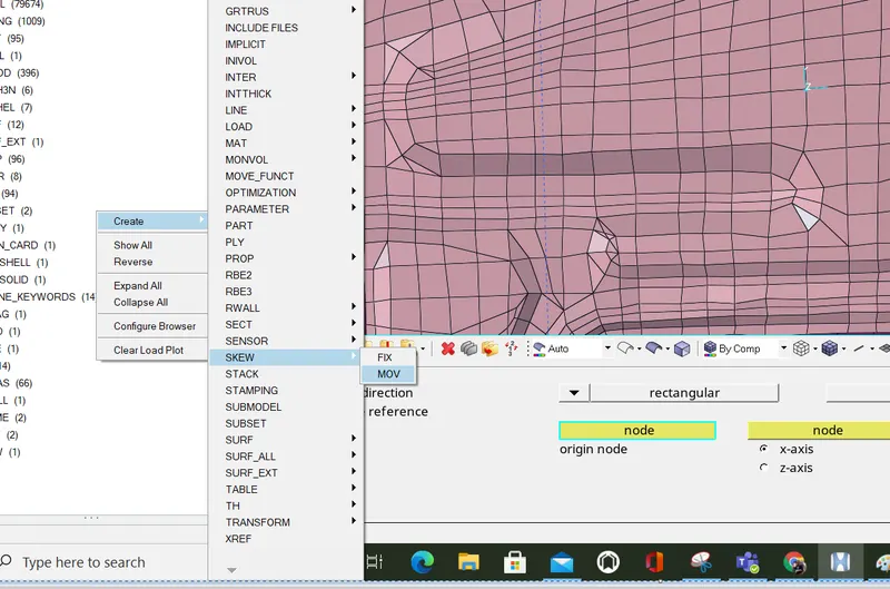
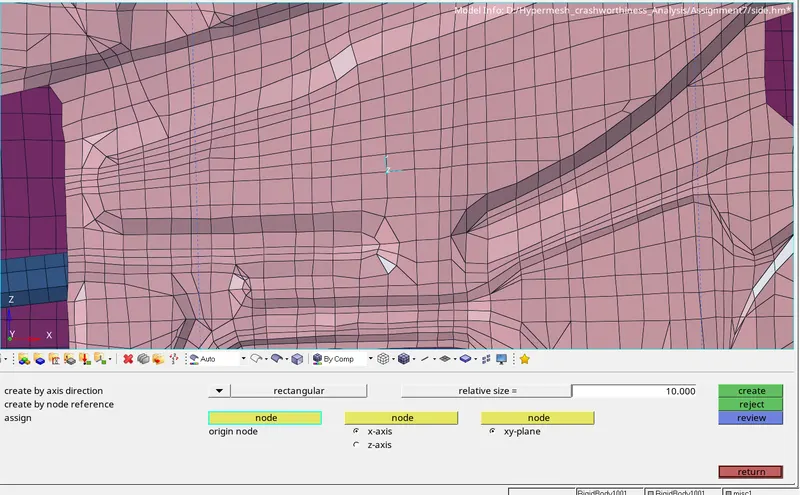
Output Request for Peak Velocity - Inner Door
Create TH(Time History) Goto - Model Browser - Create a new output Block
In the Entity ID - select node and for lskew - select the created Skew.
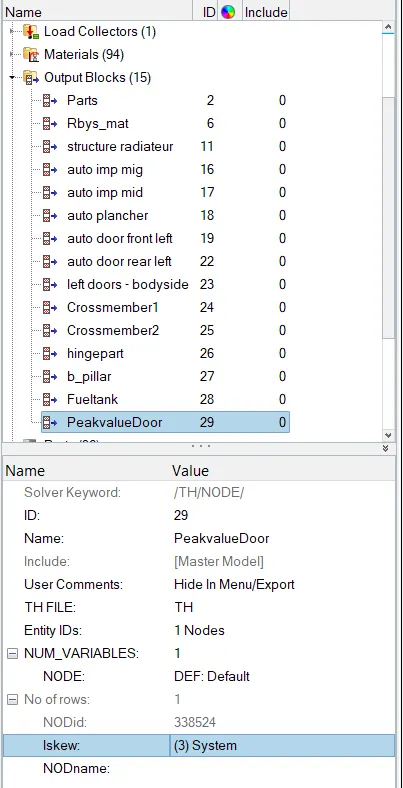
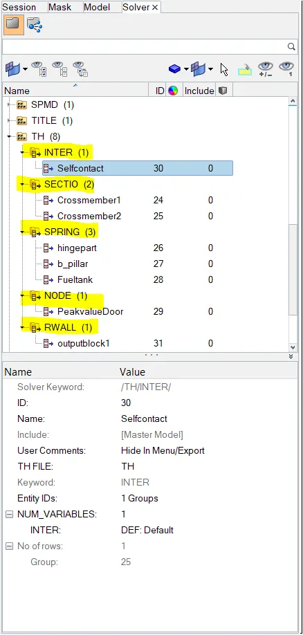
Output File Request as shown in below Image.
Time Step Control
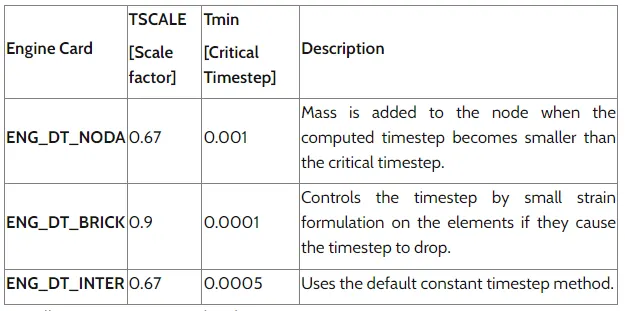
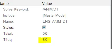
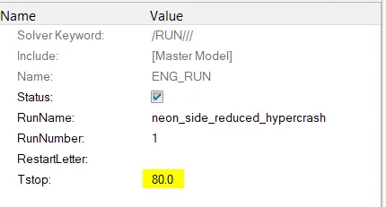
Provide ENG RUN TIME and ENG ANIM DT as following.
Run The model checker as shown in below Image and delete any errors occured.
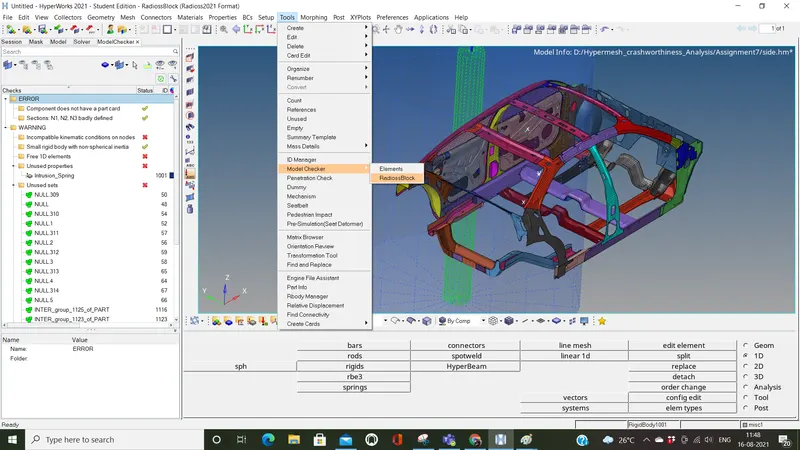
Delete any Unused Entity by following below steps.
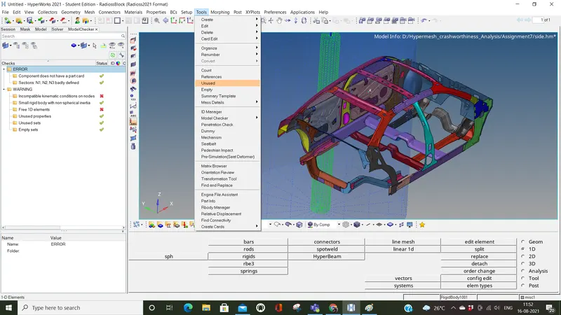
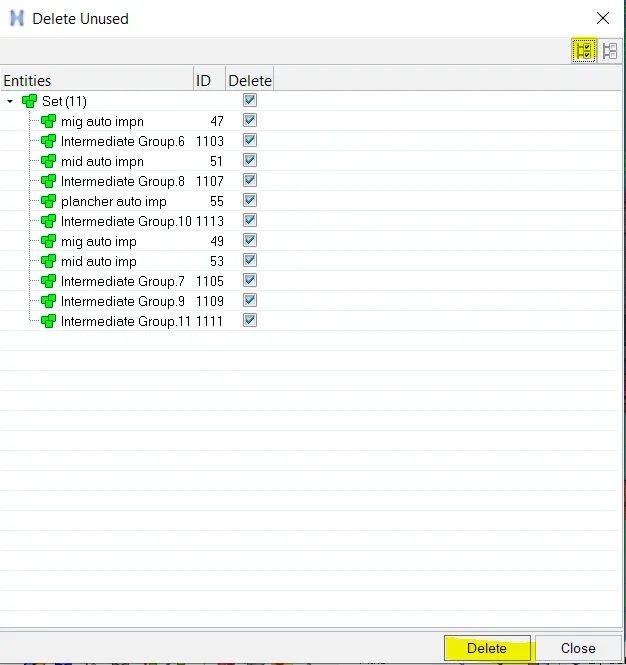
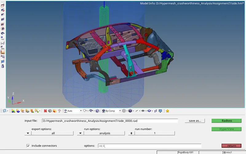
Now Run The Analysis
Goto -Analysis - Radioss - Enter the value -nt 4 and run.
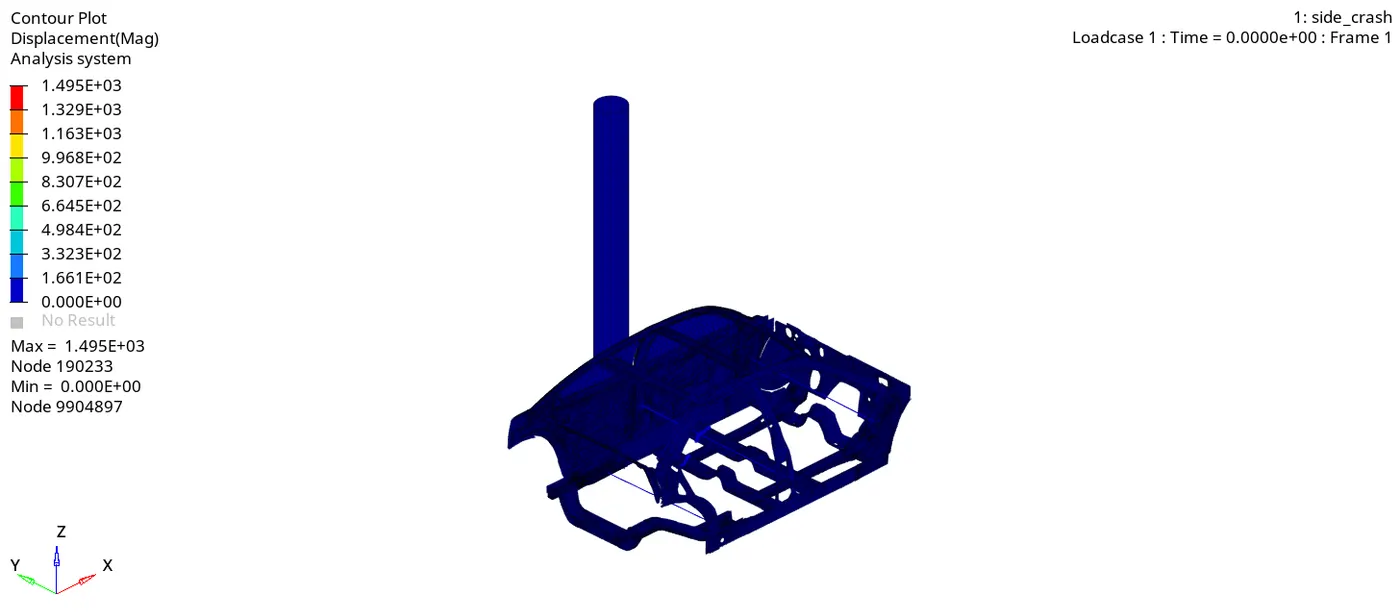
Displacement
Von Misses
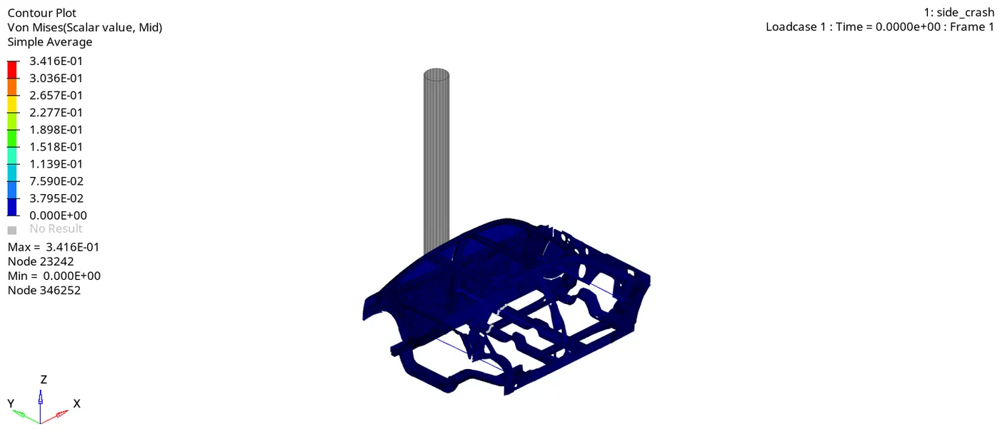
The above Crash Simulation of the Car we can observe that Car Body is impacting on a Pole. After the impact the BIW of Car is deforms and the vehicle body gets contracted around the pole.
Also The stress is more on B Pillar and cross member as this was the point of impact and then the stress is transferred in other areas and distribution of stress is proper.
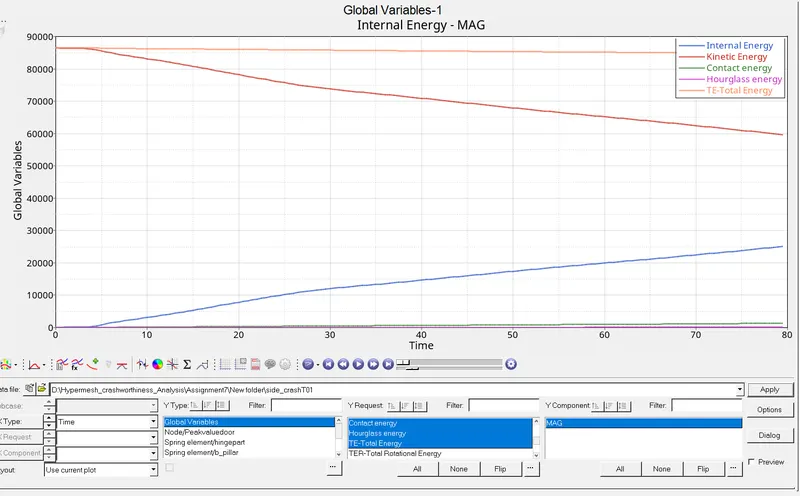
From The above plot we can see that there is high amount of kinetic energy at the start of simulation but as the it progresses the kinetic energy in car is decreases and gets converted into internal energy and the internal energy increases. The Total energy is almost constant at 85000 and due to some energy loss which we can see in the contact energy in the model as we have defined the value of friction in TYPE 7 interface due to which contact energy is generated.
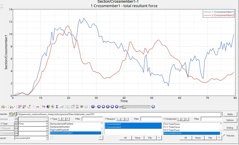
From the above plot we can see that total resultant force in rear cross member is more than the cross member 1. Cross member 2 experiences more force as it is inline with the pole.
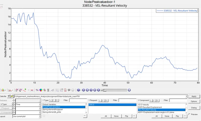
From the above plot we can see how much the actual inner side of door moves in the driver direction during impact. The Peak velocity measure at the inner door point is 15.8mm/ms after that the speed is reduced drastically.
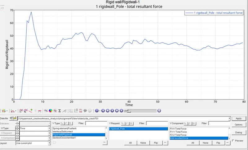
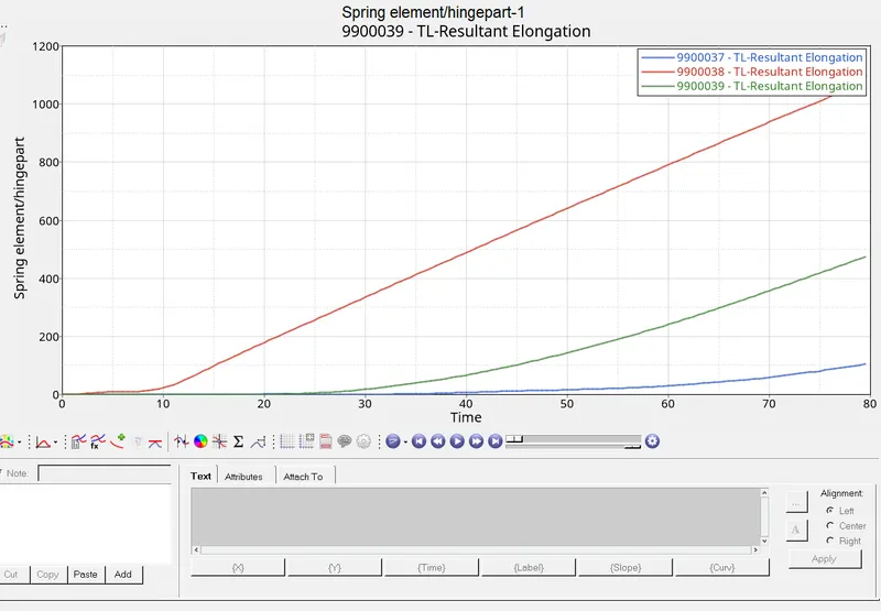
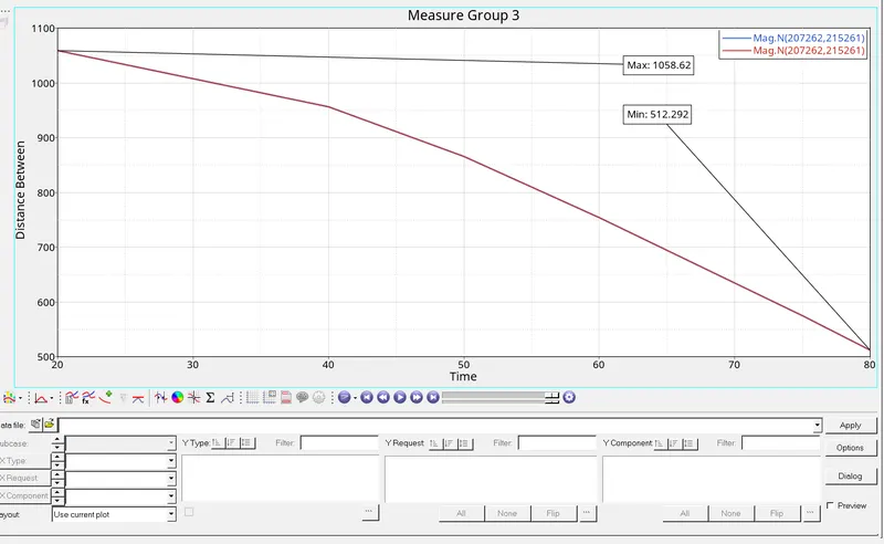
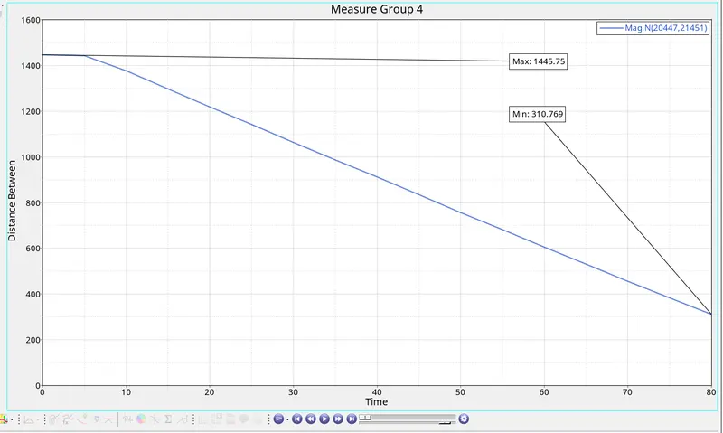
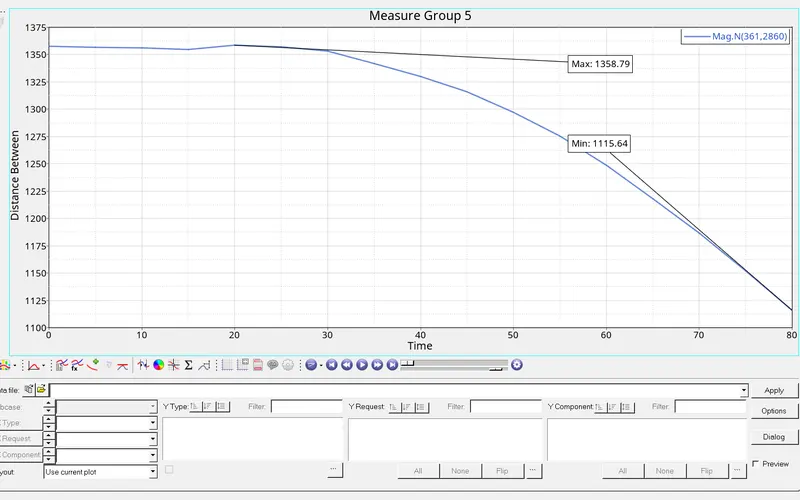
To Get the final and inital displacement value goto Measure tool in Panel and select the nodes of the springs and press F.
For plotting the Graph to get the min/max value create plot as shown in below Graph figures.
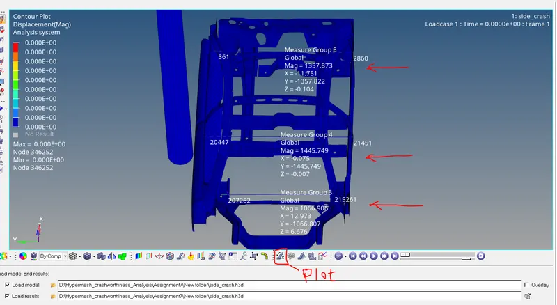
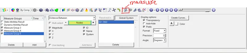
Fuel Tank Intrusion.
The final Displacement at Fuel Tank is 1058.6 and the Initial Distance of fuel Tank is 512.2
therefore Total Intrusion is 1058.6-512.2 = 546mm
B-Pillar Intrusion
The final Displacement at B pillar is 1445.7 and the Initial Distance of fuel Tank is 310.7
therefore Total Intrusion is 1415.7-310.7 = 1135 mm
Hinge Pillar Intrusion
The final Displacement at Hinge Pillar is 1358.7 and the Initial Distance of fuel Tank is 1115.6
therefore Total Intrusion is 11358.7-1115.6 = 243mm
Conclusion:
The Model was simulated for side pole crash test and the result were discussed.From the output file the energy error and mass error are within acceptable range. Cross member 1 and 2 are the impact zone and aborbing forces. So improving the sross section arear by reinforcement or material change can improve their performance. However, Please note that this is not the fully loaded model a lot of missing eleemnts in this model such as seats and its reinforcement Cross car beam Actual fuel tank and Other reinforcements were missing from the BIW and including these will give a realistic intrusion value.