Assignment 7-Side Pole Crash Simulation Challenge
OBJECTIVES :
Neon side crash -BIW
- Check unit system and either follow [Mg mm s] or [Kg mm ms].
- Create appropriate interface ,friction 0.2 and recommended parameters.
- Make sure of no penetration and intersections.
- Create rigid wall with friction 0.1 as per referance model.
- Compare the model weight with the referance model and use added masses to reach target weight 700kg while getting CG about the required range.
- Initial velocity as shown in picture.
- Use model checker to ensure good quality.
- Timestep :0.5 to 0.1 microseconds.
- Run 80ms.
Output requests:
- Sectional force in the cross member.
- Intrusion at B pillar,hinge pillar and fuel tank region.Provide recommendation on what can help to reduce Fuel tank intrusion.
- Peak velocity of inner node of the door.
Check unit system and either follow [Mg mm s] or [Kg mm ms].
- Now first we will open the 0000.rad file to check the unit system.

- AS you can see the unit system here is in Kg mm ms.
Create appropriate interface ,friction 0.2 and recommended parameters.
- Now we will create TYPE7 interface and apply the recommended parameters to it.
- For TYPE 7 interface go to the MODEL>CREATE>CONTACT. And set the parameters As shown below:
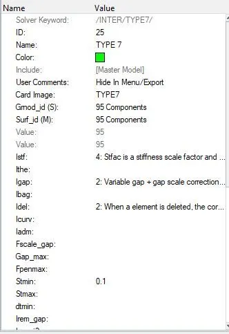
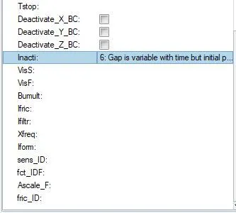
- Now the parameters are done we will go for the next step.
Make sure of no penetration and intersections.
- For this we will open the HyperCrash and import the same model and check the pentration.
- For penetrations go to QUALITY>CHECK CONTACT SOLVER INTERFACE as shown:
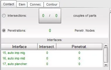
- As you can see there is no penetrations and intersections.
Compare the model weight with the referance model and use added masses to reach target weight 700kg while getting CG about the required range.
- Now for this we will go to MASS>BALANCING
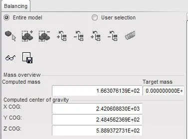
- As you can see the mass is 166 kg so we need to make it near about 700 kg and with that we have to keep COG in the middle of the car .
- To add mass go the the LOADCASE>ADDMASS as shown:
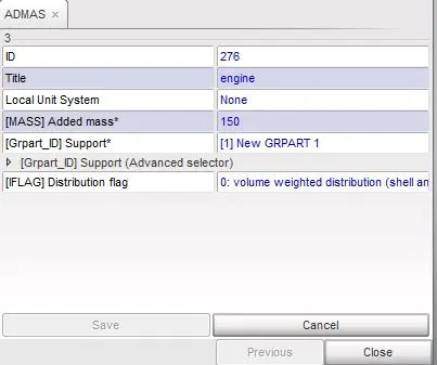
- To get the CoG we have to add the mass accordingly as shown below:
- The yellow part is where the mass is added.
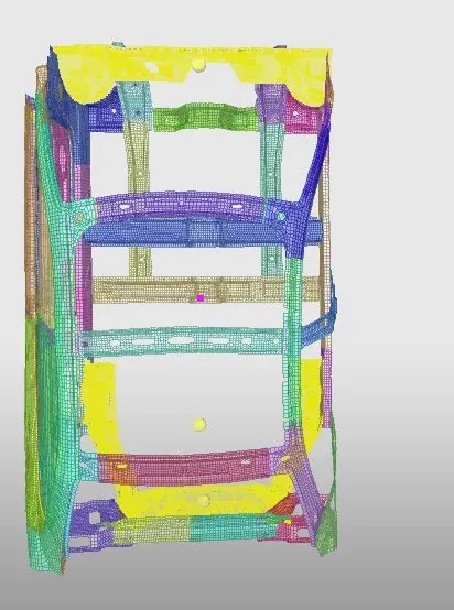
- And we have created the CoG at the center.
Create rigid wall with friction 0.1 as per referance model.
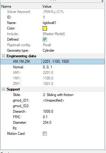
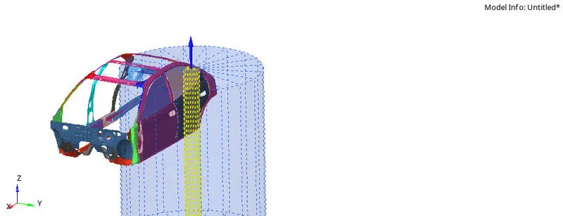
- For this go to the SOLVER>CREATE>RWALL>CYLINDRICAL
- We need pole so we are creating cylindrical wall. As shown below:
Initial velocity.
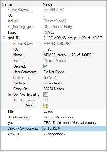
- For initial velocity we will create a card for that go to SOLVER>BCS>INIVEL as shown:
- Velocity is given as 35mph as we our units are in mm and ms then 35 mph= 15.64 ms
- In this we can give the velocity in the direction of Y axis.
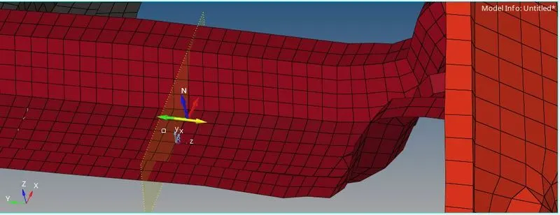
Now we will create a section
- So to create section first we will create frame.
- For frame go to the SOLVER>CREATE>FRAME>MOVE as shown:
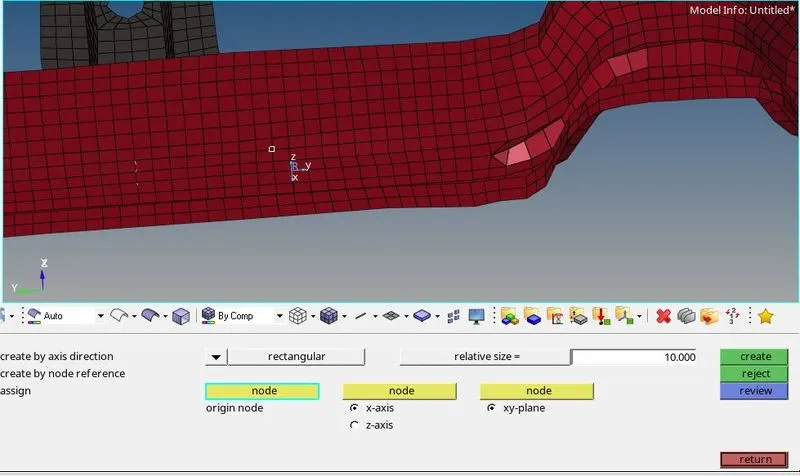
- After creating frame we will create section.
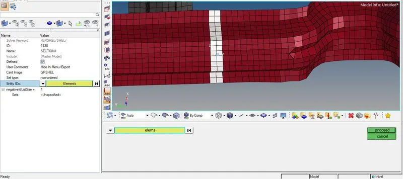
- For creating section we need group of nodes for that we will create it. To create it go to SOLVER>CREATE>GRSHEL>SHEL as shown below:
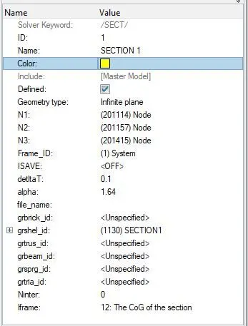
- Now for section go to the SOLVER>CREATE>SECT as shown:
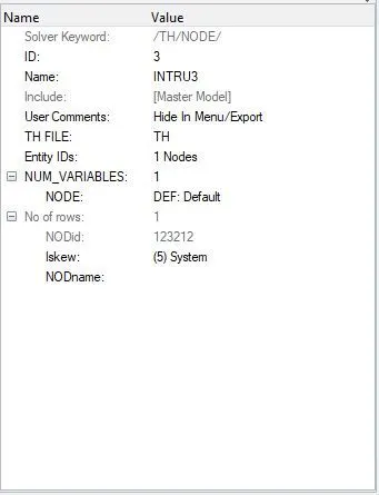
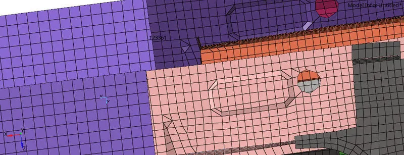
Now we will create intrusion point.
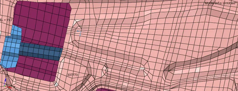
- To create intrusion point we have to create a SKEW.
- The intrusion point is shown below:
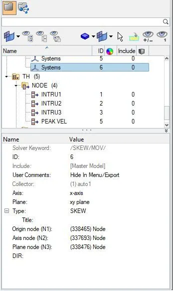
CREATING PEAK VELOCITY
- Creating a new local coordinate in SKEW collector of solver browser and giving origin,axis and plane nodes. As shown:
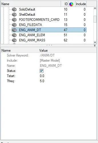
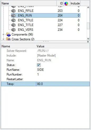
- Now for TimeStep and Run time we have to put values as given which is shown below:
- For TimeStep open ENG_ANIM_DT file
- For RUNTIME open ENG_RUN
Starting the Simulation of Frontal Crash of the given BIW
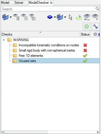
- Before running the file check for any errors in the model.
- To check the errors in the Hypermesh Tools>Model Checker>Radioss block
- Errors in the model is shown if there are any errors, also it will show the warnings.
- The solver will run the simulation if there are any warnings but will not if there are errors.
- To start the simulation Analysis>Radioss>Save as Name_0000.rad in a new folder>-nt 4 in the options for faster simulation>Radioss
- Now simulation is show below:
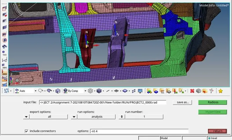
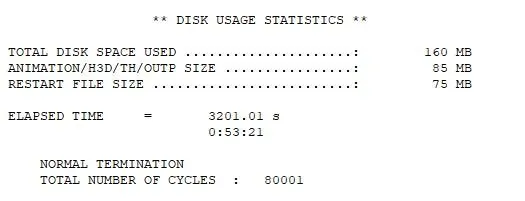
- Now the elapsed time and total number of steps are shown below:
- Now we will check of the error %:
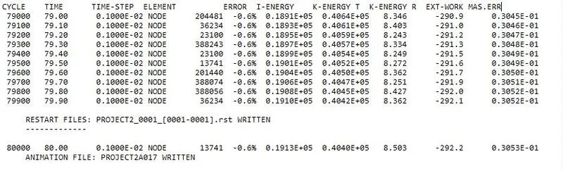
- As we can see, the energy error is -0.6%. It is definitely acceptable within range of -10% to +5% error. In addition to that, the mass error is 0.03213, which means that a negligible quantity of mass of was added during the simulation, possibly for the sake of time step control/stabilization.
- Now switch to the HyeprView and open .h3d file.
- It will look as shown below:
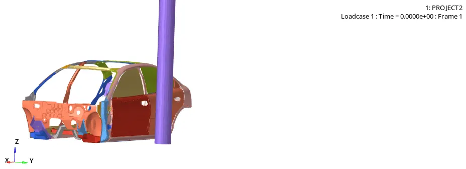
- VON MISES
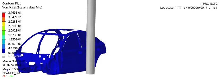
- From the Von Mises stress plot, we can say that the stress distribution is quite good in the vehicle after the crash. There are very few areas where we can see stress concentration. Generally, the stress is more in door region as it is the first point of impact.
- Now for plotting graphs open the HyperGraph2D and then open T01 file.
INTRUSION:
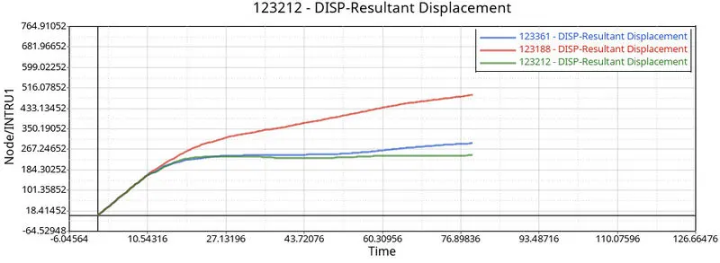
- Now here Displacement if B pillar is more that other two which is 300mm
- The displacement of Hinge pillar is 190mm
- And the dislpacement of fuel tank is 200 mm
PEAK VELOCITY
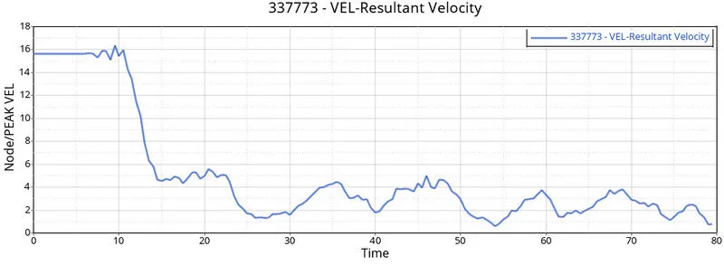
- The velocity is maximum at the start which is 16m/s at 10ms.
SECTION
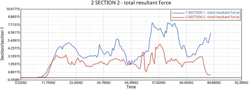
- Here we can see that the sectional forces in the front cross-member (Hinge section) is less as compared to the resultant forces in the rear member. This is because the rear member (B pillar section) is closer to the pole axis and takes up lot of forces.
OUTCOMES:
- Able to define the peak velocity at a perticular point.
- Able to balance the CoG at the center.
- Corrected the errors in model checker.
- Able to create the required sections.
- Able to provide the output results in the output blocks.
CONCLUSION
- The Side Pole Crash Test of the given car BIW is Simulated in Hypermesh and required output requests are plotted and explained.
- The Mass is balanced.