Assignment 7-Side Pole Crash Simulation Challenge
ASSIGNMENT 7: SIDE POLE CRASH SIMULATION.
AIM: Neon side crash -BIW
- Check unit system and either follow [Mg mm s] or [Kg mm ms].
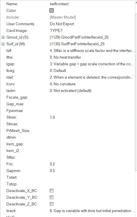
- Create appropriate interface ,friction 0.2 and recommended parameters.
- Make sure of no penetration and intersections.
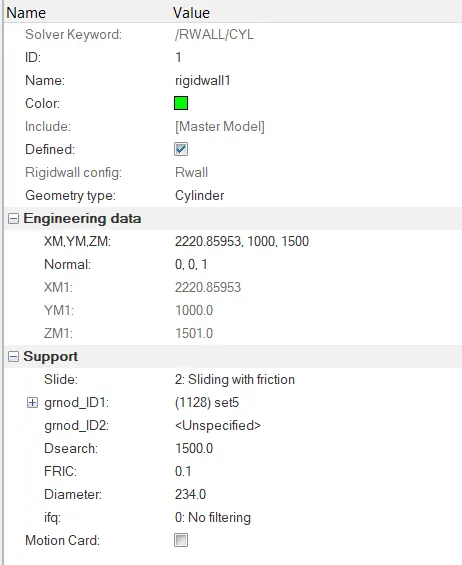
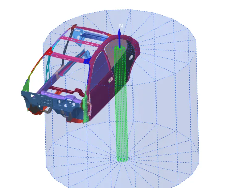
- Create rigid wall with friction 0.1 as per referance model.
- Compare the model weight with the referance model and use added masses to reach target weight 700kg while getting CG about the required range.
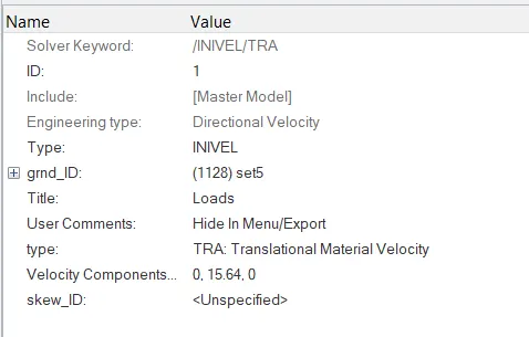
- Initial velocity as shown in picture.
- Use model checker to ensure good quality.
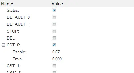
- Timestep :0.5 to 0.1 microseconds.
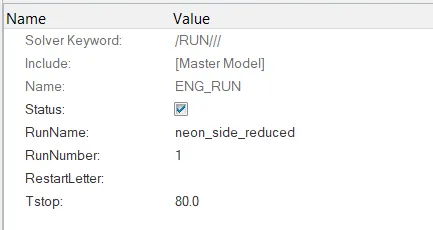
- Run 80ms.
Output requests:
- Sectional force in the cross member.
- Intrusion at B pillar,hinge pillar and fuel tank region.Provide recommendation on what can help to reduce Fuel tank intrusion.
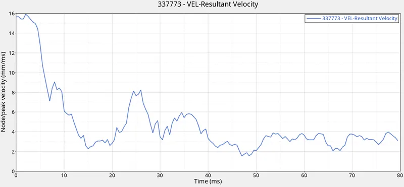
- Peak velocity of inner node of the door.
PROCEDURE:
1) Import the provided rad files.
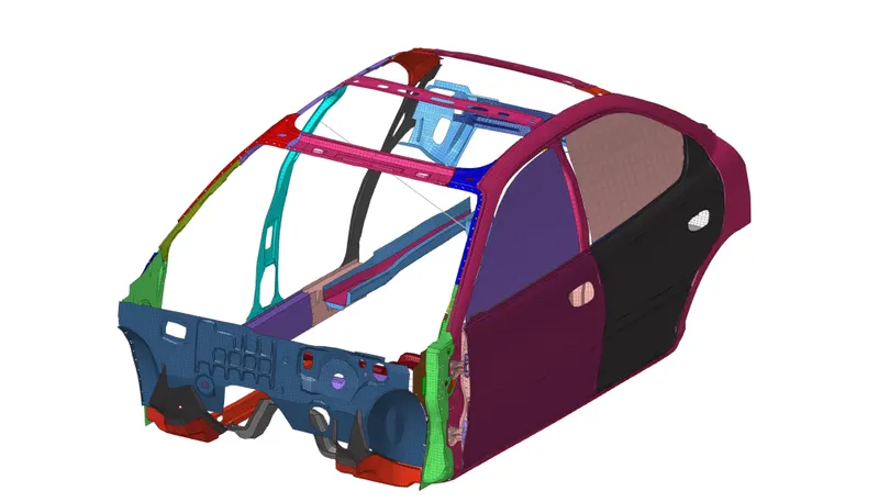
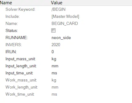
2) To check the working units of the imported rad file check the BEGIN card to know the units.
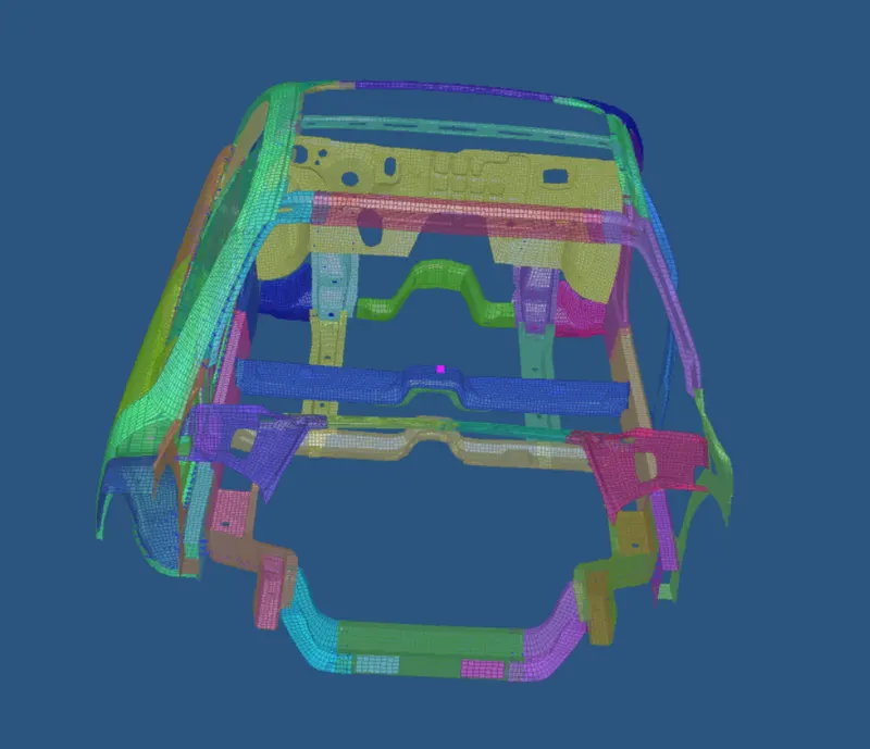
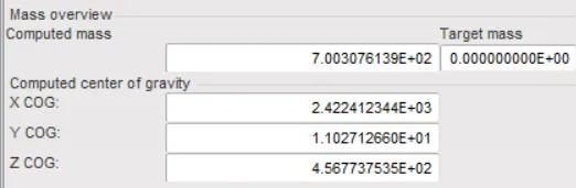
3) We need to check the mass of the model. We need to add mass to make it 700kg and also balance the CG.
Mass was added from Solver>Right click> ADMAS and then add the mass according to the parts.
4) A type 7 self contact was created with the following parameters-
5) A rigid pole was created by right clicking in solver menu>RWALL>CYL and the parameters for the wall were as shown below
6) Initial velocity in y direction was given from Solver>Boundary Conditions>INIVEL and the parameters for the initial velocity is as shown below -
7) Cross-sections were also created from solver browser.
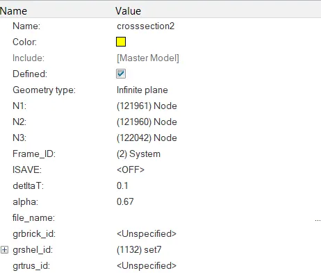
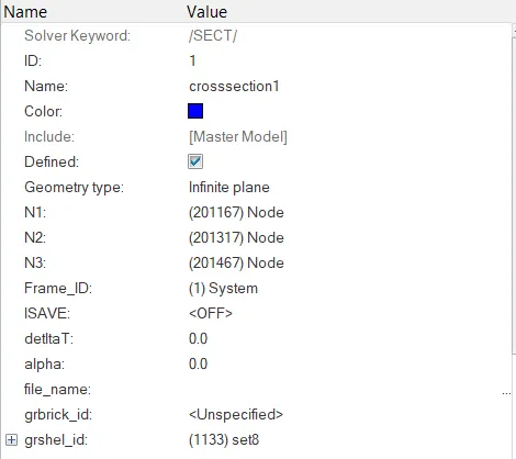
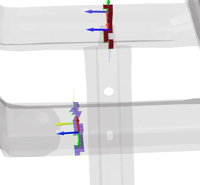
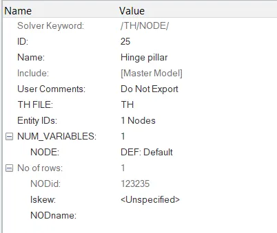
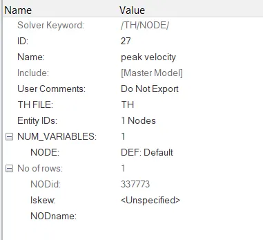
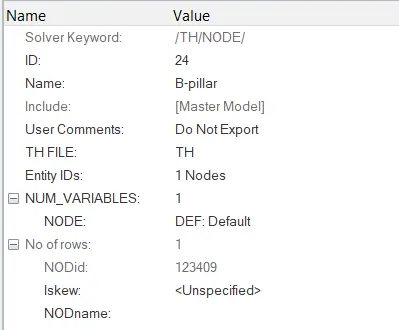
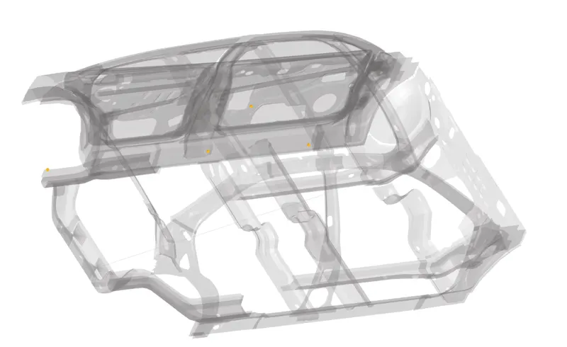
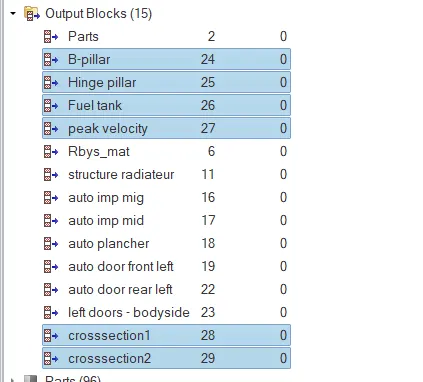
8) Now creating intrusions for the b-pillar, hinge pillar and fuel tank by right clicking the solver browser>TH>NODE
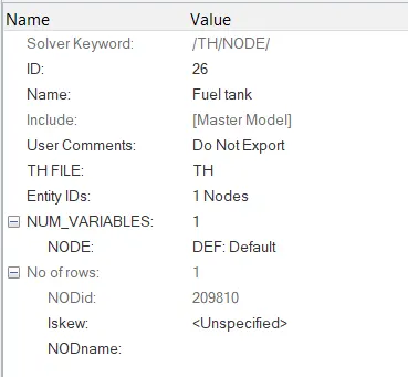
9) Creating output blocks for cross sections too.
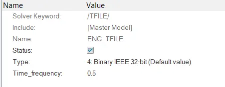
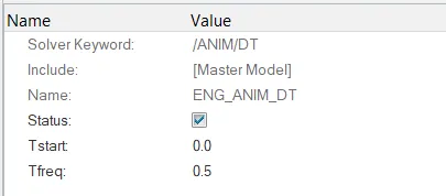
10) The time frequency and runtime were changed according to the requirement.
OUTPUTS:
After running the analysis we run h3d file in hyperview to know the deformation that occurs after the crash.
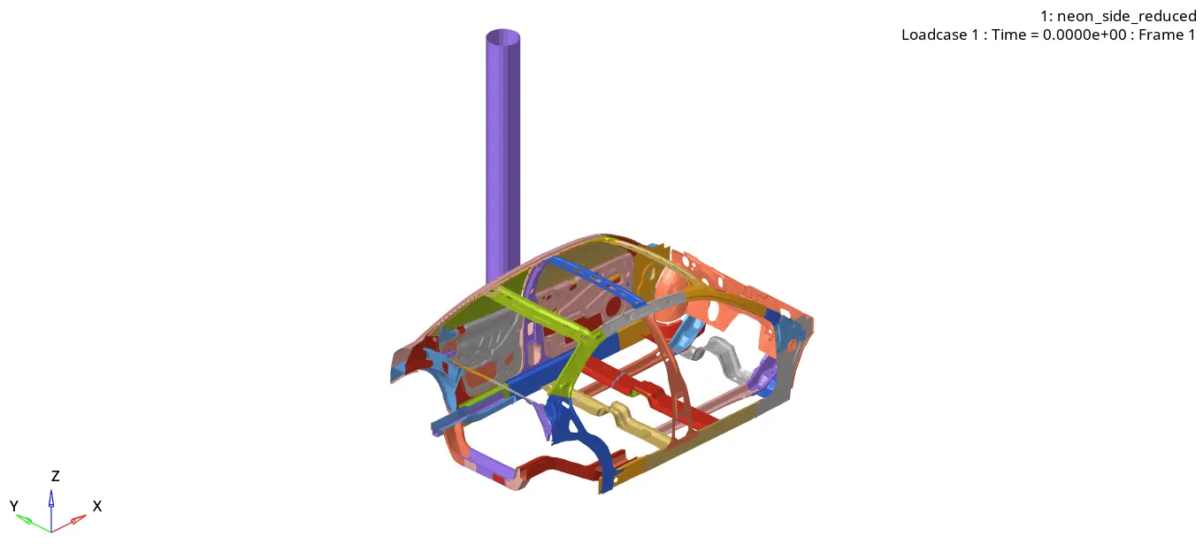
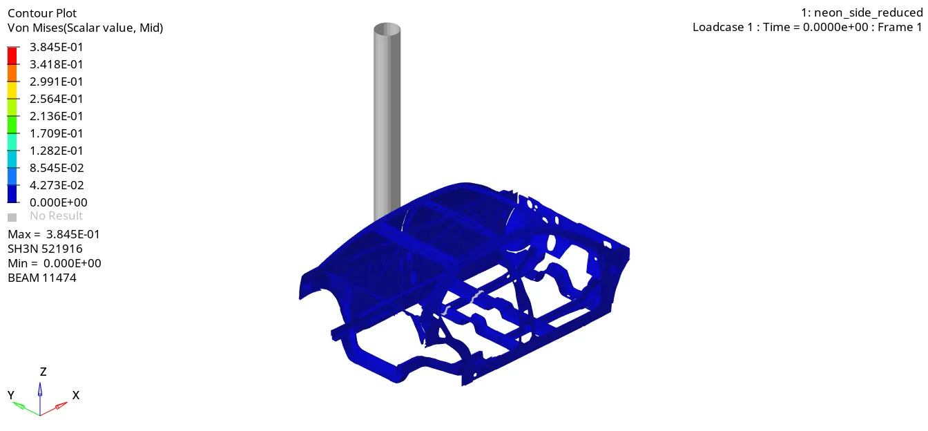
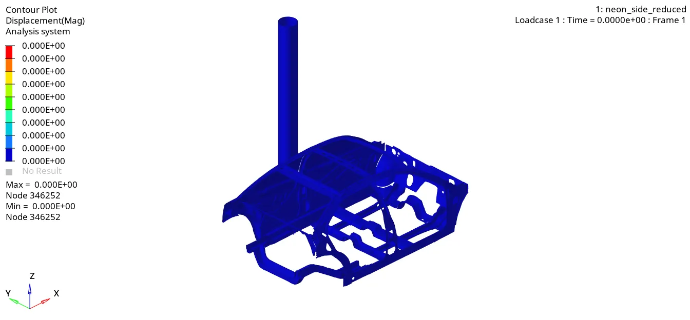
The displacement and vonmises stresses induced are as shown below;
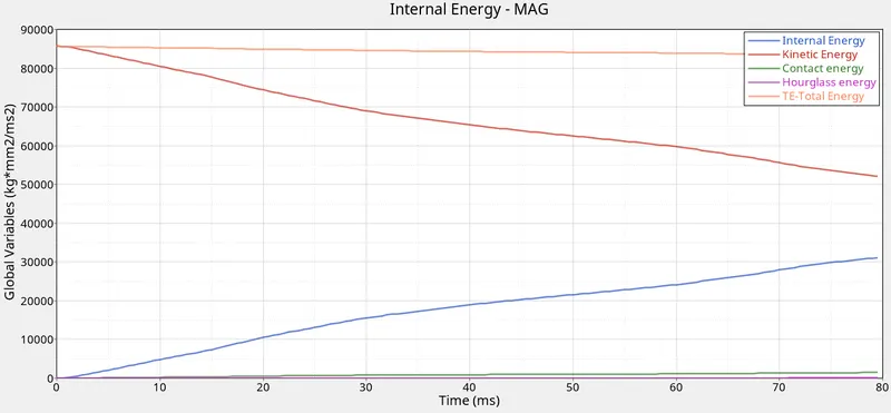
The energies observed during the crash are as shown below;
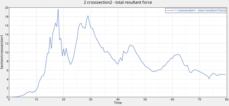
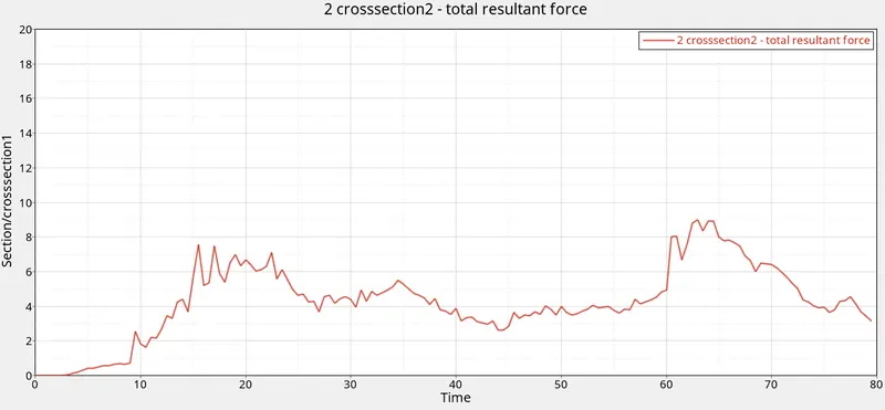
The forces at the cross-sections are shown below;
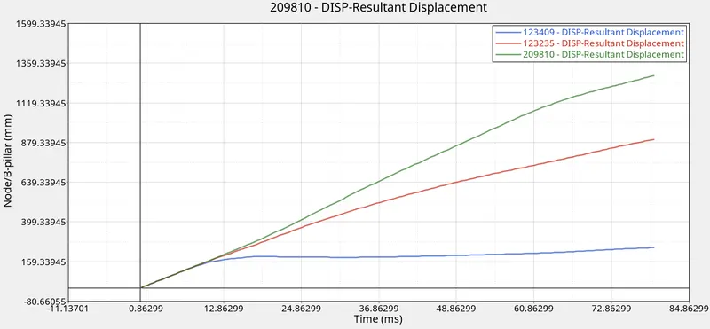
The displacement graphs for the intrusions are as shown below;
The peak velocity graph of inner node of the is as shown ;
OBSERVATIONS:
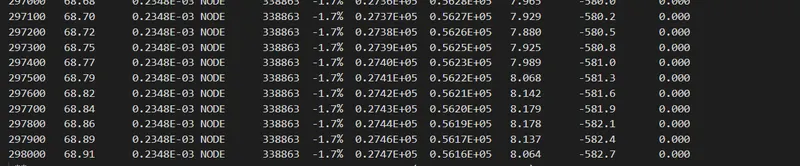
The energy and mass error were in the acceptable so the simulation was acceptable.
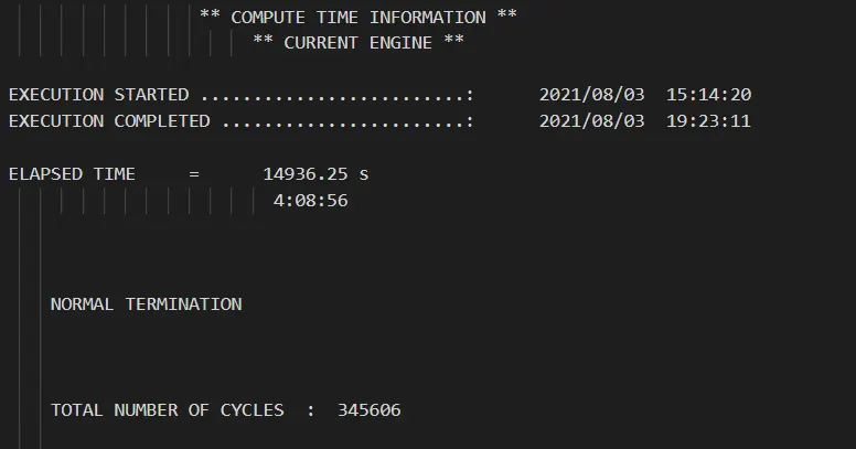
The time required and animation cycles were as shown below
Some hourglass energy occured but are negligible due to the magnitude of other energies.
The forces experienced by the cross section 1 is more that cross-section 2 as the force impacts occurs near the cross section 1.
The fuel tank intrusion is higher than any other intrusion.
The peak velocity of node under the door is more than the impact velocity.
CONCLUSION:
- The side crash analysis is completed for the given dodge neon model.
- The maximum energy error is about -1.7% which is acceptable.
- The intrusion at fuel tank can be reduced by introducing a more stiffer material or more cross members should be added to support the fuel tank.
LEARNING OUTCOMES:
- Setting up the model for crash analysis.
- Analysis of plots to get to conclusion.