Assignment 7-Side Pole Crash Simulation Challenge
objective :-
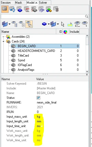
- Check unit system and either follow [Mg mm s] or [Kg mm ms].
- Create appropriate interface ,friction 0.2 and recommended parameters.
- Make sure of no penetration and intersections.
- Create rigid wall with friction 0.1 as per referance model.
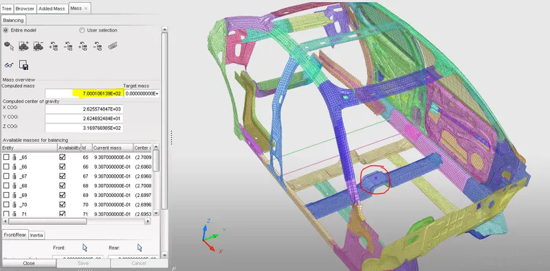
- Compare the model weight with the referance model and use added masses to reach target weight 700kg while getting CG about the required range.
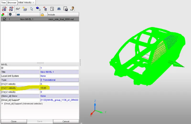
- Initial velocity as shown in picture.
- Use model checker to ensure good quality.
- Timestep :0.5 to 0.1 microseconds.
- Run 80ms.
Output requests:
- Sectional force in the cross member.
- Intrusion at B pillar,hinge pillar and fuel tank region.Provide recommendation on what can help to reduce Fuel tank intrusion.
- Peak velocity of inner node of the door.
case setup :-
- import model into hypermesh and hypercrash
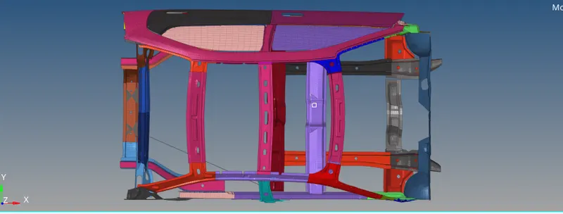
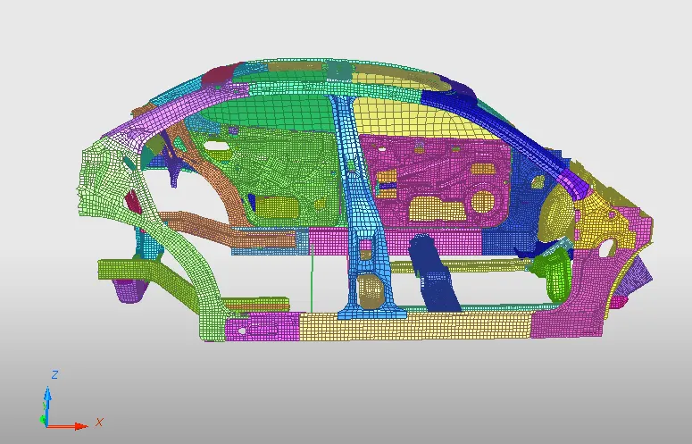
- Check unit system and either follow [Mg mm s] or [Kg mm ms].
- Create appropriate interface ,friction 0.2 and recommended parameters.
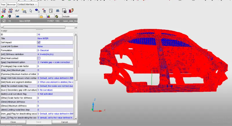
TYPE 7 Contact interface is used to define sef-contact for the whole model. the nodes are assigned as slavesand elements are assigned as masters.
- Recommended parameters
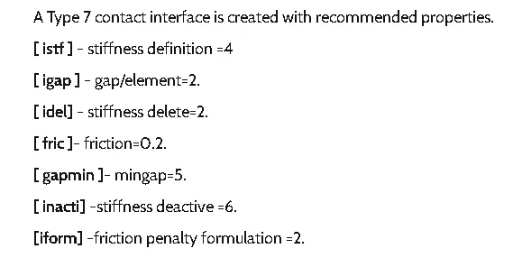
- Applied parameters
- Make sure of no penetration and intersections.
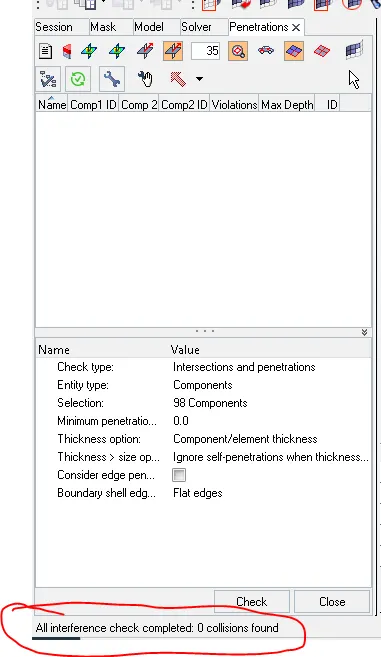
there is no penetration and intersections in the model.
- Create rigid wall with friction 0.1 as per referance model.
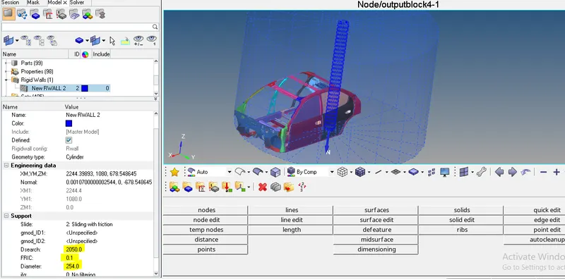
Created a Cylindrical rigid wall with friction 0.1, Diameter 254mm, Dsearch2050mm.
- Centre of Gravity (COG)
Location COG is very imp for crash simulations, rolling and crash behaviour of car dependes on location of COG. The distributed mass of load 700kg is added to the BIW rail components using added mass option in hypercrash.
- Intial velocity
Given velocity 15.65mm/ms in y-axis direction for the entire model.
- Time step
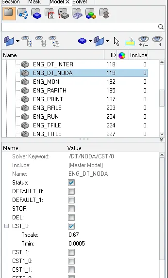
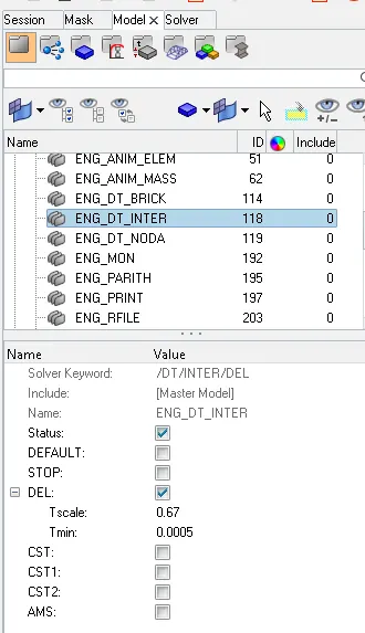
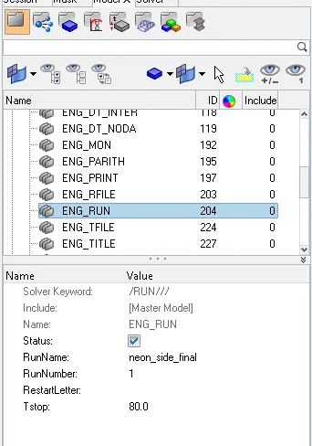
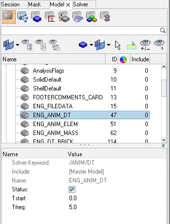
the constant time step for nodes DT/NODA/CST is 0.0005, constant time step for interfac DT/INTER/CST is 0.0005,runtime is 80ms,animation freequency is 5ms
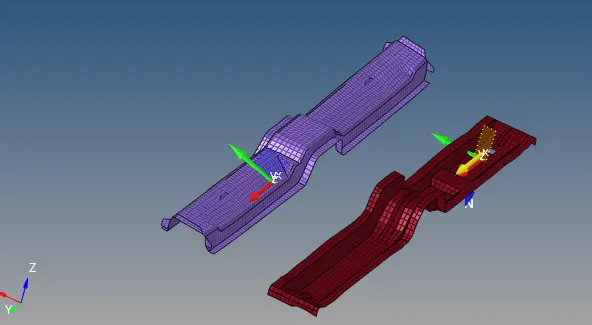
- Cross sections
Sections are created on cross members to check the how much force passing through it, while crash happen.
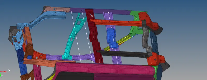
- Instrusions
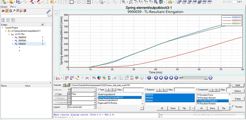
Created Intrusion at B pillar,hinge pillar and fuel tank region, to know the shrinkage of volume while crash happen.
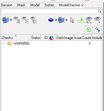
- Model checker
Make sure no errors in model and try to reduce warnings as much as possible.
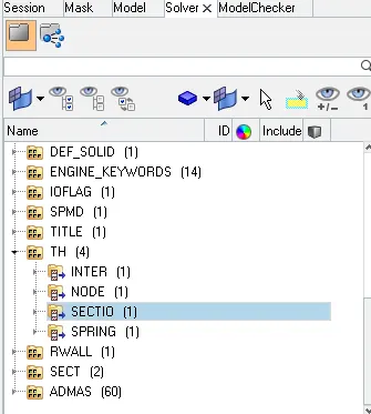
- Time history
Created TH cards for intrface ,intrusions, sections and velocity at inner node of the door.

Now case setup is completed go for simulation.
RESULTS :-
Sectional force in the cross member
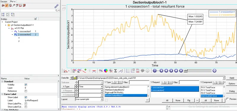
We created two sections at different locations on cross members, one section is created left side of the member, another one is created at right side of the member. In this case setup pole is created at left side of the car that is why section at left side(crosssection2) having more force than section at right side(crosssection1).
Sectional force in the cross member
We created two sections at different locations on cross members, one section is created left side of the member, another one is created at right side of the member. In this case setup pole is created at left side of the car that is why section at left side(crosssection2) having more force than section at right side(crosssection1).
Intrusion at B pillar,hinge pillar and fuel tank region
Peak velocity of inner node of the door
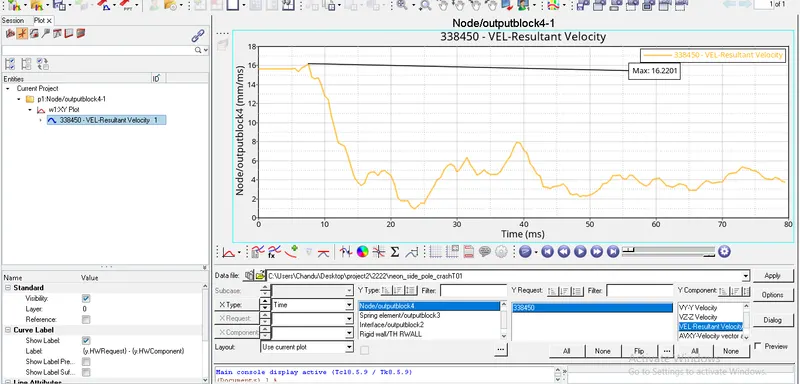
- Peak velocity of inner node of the door is 16.2201mm/ms.
Review of output file

- energy error is -2.4%
if the energy error is negative it means some energy is dissipated may be in the form of hourglass energy. the acceptable range for energy error is 10-15% ,but in this model its error -2.4% so this model is acceptable.
- Mass error = 0.4445E-04 = 0.00004445 = 0.004445%
Acceptable range for Mass error is <2% , hence this model is acceptable.
- No.of.cycles = 159900
- Time step is constant through out the simulation.