Assignment 7-Side Pole Crash Simulation Challenge
AIM:
-Side pole crash simulation neon BIW using RADIOSS Solver and Pre-processor using Hypermesh/Hypercrash.
OHJECTIVE:
Neon side crash -BIW
- Check the unit system and either follow [Mg mm s] or [Kg mm ms].
- Create an appropriate interface, friction 0.2, and recommended parameters.
- Make sure of no penetration and intersections.
- Create a rigid pole with a friction of 0.1 as per the FMVSS 214 standards.
- Compare the model weight with the reference model and use added masses to reach the target weight of 700kg while getting CG about the required range.
- Initial velocity - 20mph, as per the standards.
- Use a model checker to ensure good quality.
- Timestep:0.5 to 0.1 microseconds.
- Run 80ms.
Output requests:
- Sectional force in the cross member.
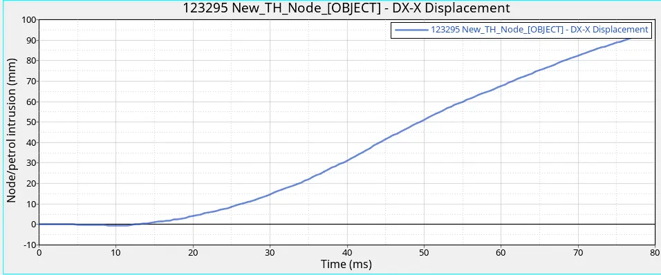
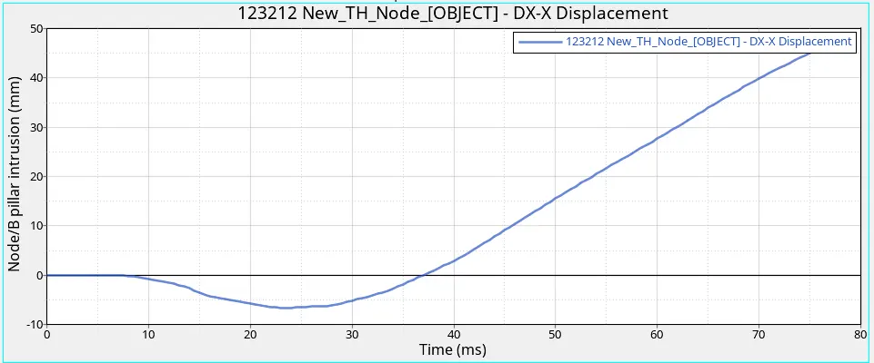
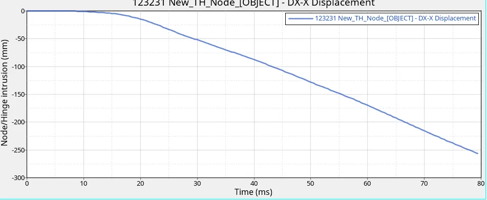
- Intrusion at B pillar,hinge pillar and fuel tank region. Provide recommendations on what can help to reduce Fuel tank intrusion.
- Peak velocity of an inner node of the door.
CASE SETUP AND EXECUTION:
1. Check the unit system and either follow [mg mm ms] or [kg mm ms]
Step 1: Import the neon model (starter file of '.0000rad' file).
In Hypermesh: Go to menubar-file-import-solverdeck-selcet '0000.rad'-import.
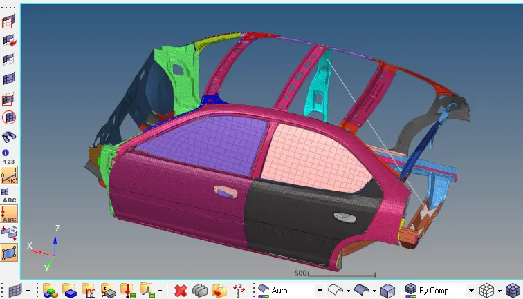
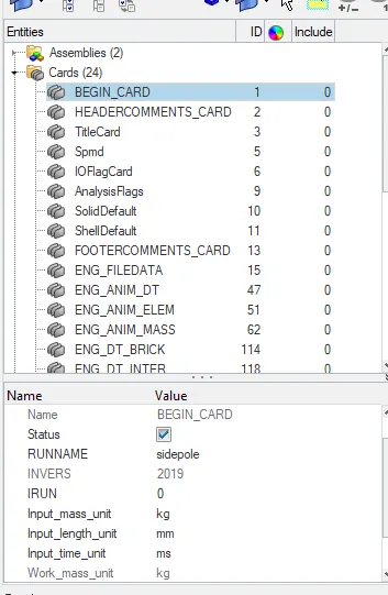
-Check unit system (mm mg ms) or (mm kg ms)
-Go to model browser>cards>Begin_card.
-click Begin_card check the unit sytem.
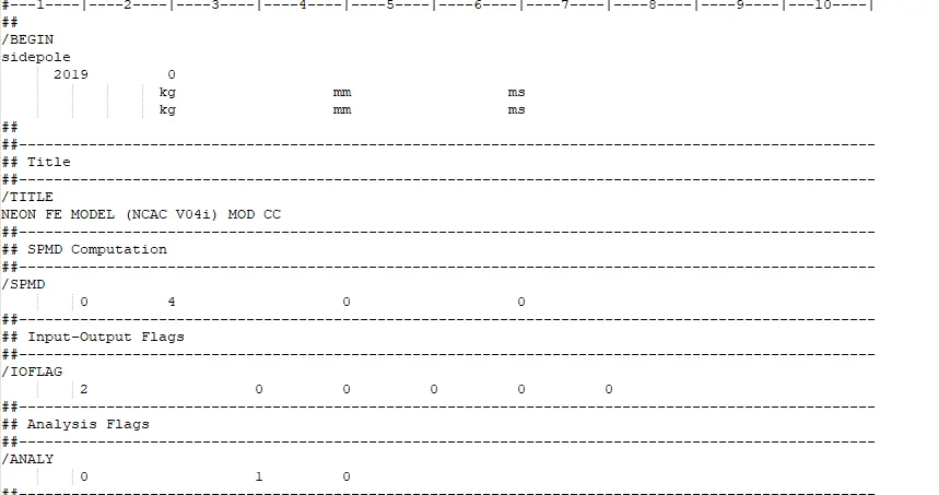
-In other method to find the unit system is oooo.rad file.
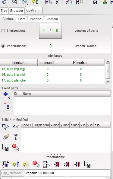
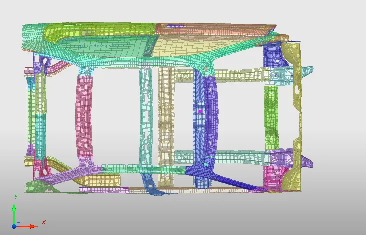
2. Check penetration and intersection :
-Go to quality>check all solver interface>
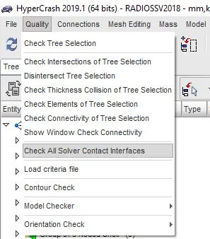
- click the above we get the penetration list.
-No penetration
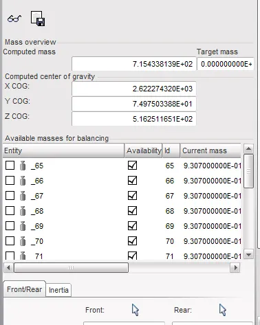
3. Add mass and to reach 700k kg:
- Now going to adding the mass.
-Before that chech COG(centre of gravity).
-
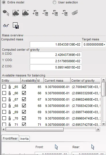
-Check the centre of gravity.
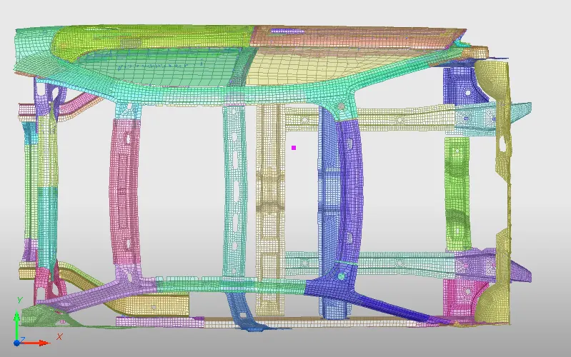
-Need to add mass to control the COG and add reach 700kg.
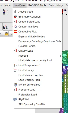
-Go to Loadcase>Added masses.
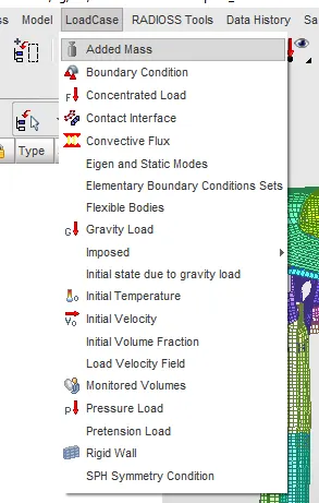
-selected add masses>create> type1 selected.
-It distrubuted the mass each node in the group.
-Going add mass now
Mass kg
Left side fuel support 50
right side fuel support 50
Seat and driver 150
Dash board 200
B pillar 100
-After adding mass go to check mass balancing.
-Go to Loadcase>Added masses.
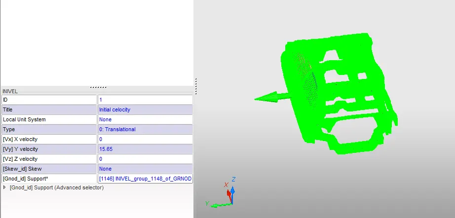
4. Assign initial veocity:
-Adding initial velocity go to Load case>initial velocity.
-choose the translation direction.
-Give value as 20mph (15.65)ms
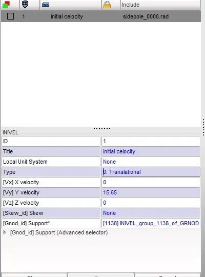
-select [Gnod_id] -select all the parts.
-After selcting it indicate the direction.
5. Create an appropiate interface, friction 0.2, and rewcomented parameter:
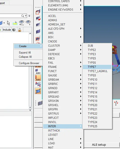
-Now going to create self contact using Type7.
-This method slave and master node are contact between them so is called self contact.
- Go to solver>create>inter>type7.
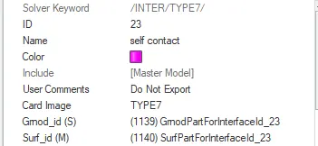
-In Gmod_id(s) - select slave node (here select all the components).
-In Surf_id(M) - select master node (here also select all the components).
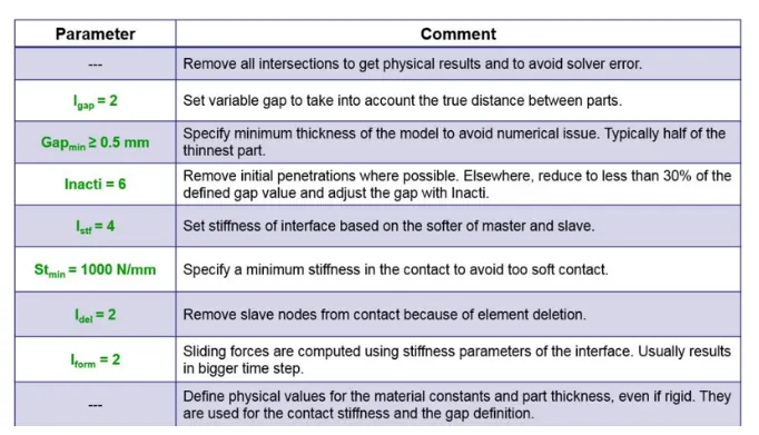
-After this type 7 follow some recomented parameter follow as below.
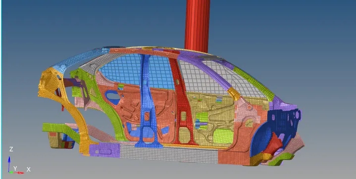
6. Create Rigid wall cylinder:
-Create rigid wall cylinder left side of the car.
- Go to solver>Rigidwall>Cyl.
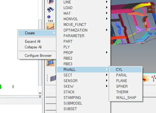
-Select rigidwall cylinder.
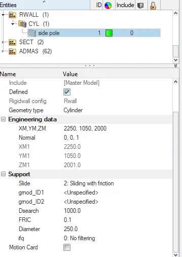
-select first node to co-ordinate direction.
-Then select normal choose z- direction.
-slide option- 2.sliding and friction.
-Diameter is 250.
-D_search as 1000 (slave node will in the dsearch).
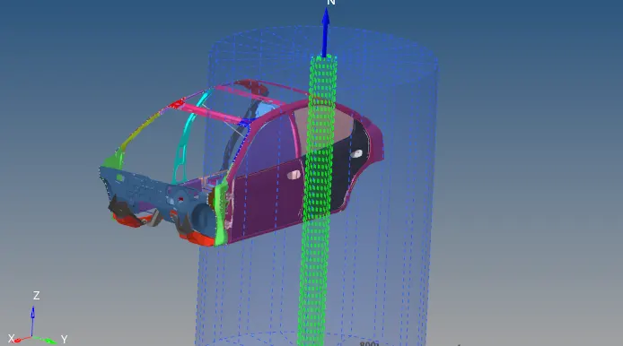
- cylinder pole created as shown below.
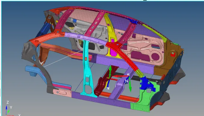
7. create cross section:
-Create section is to how much energy passes through the cross membrance.
-Before section need to create Frame.
Frame is local axis for the section.
-Go to solver>create>Frame>mov.
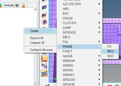
-Created the frame shown as below
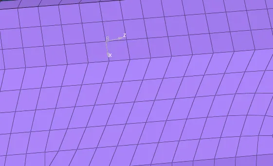
-After crete the Frame.
-Need to create>sect>sect.
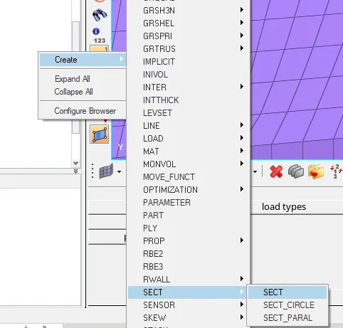
-select the sect>new crossection file open.
-select N1, N2 and N3 define direction.
-Frame_ID-- select the frame as we create before.
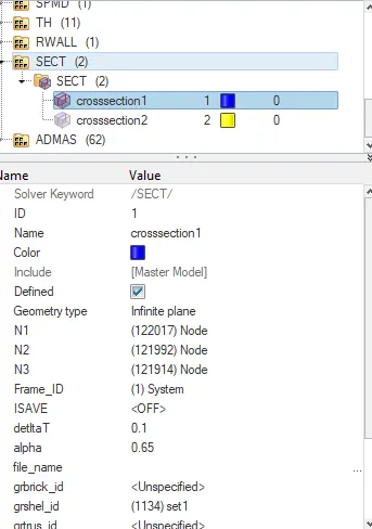
-grshel_id - select the element where have want cross section.
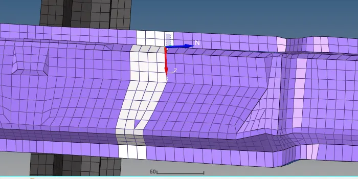
-similarly do it for another cross section.
-Just follow the above prosess.
8. Requesting output file for cross section created:
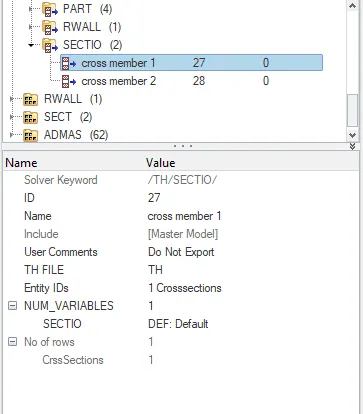
-After creating the cross section, we will request the result of time history(TH).
-Go to solver>create>TH>sectio.
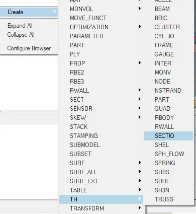
-Just select Entity iDs - choose the choose the created crossection.
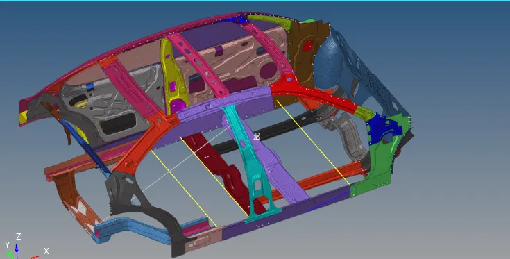
9. Create intrusion in B-pillar, Hinge and fuel tank region:
-Create intrusion go to 1D>spring-select two nodes in B-pillar, hinge and fuel tank.

-Spring is created as shown as below.
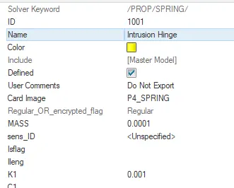
-Then we have to create property card for the spring.
-Give title, card image-P4_spring selected.
-Mass value give as low nad stiffness.
10. Requesting output file for spring intrusion created:
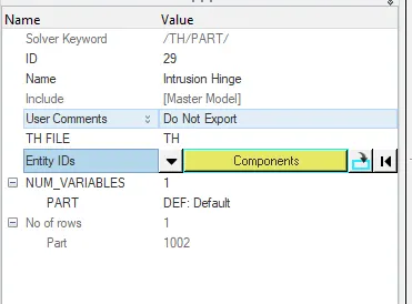
- Go to solver TH>create_new>
-Create intrusion
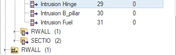
-select entity IDs-select the spring.
-Do it for remaining
11. Peak velocity of inner door:
-Find the peak velocity of inner door node.
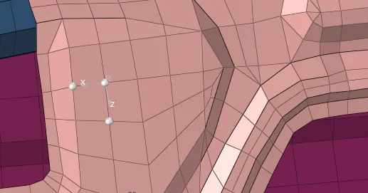
-Go to sover>create >skew>mov.
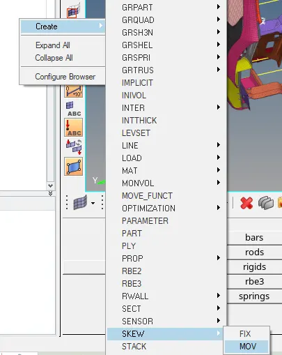
-Select the require node as orgin node then select node to define x- axis and xy-plane as shown below.
12. output request for peak velocity of inner door.
- Go to model browser>TH>create>Node.
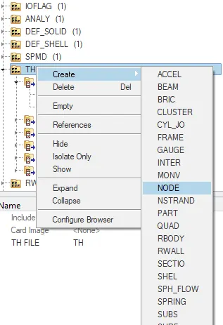
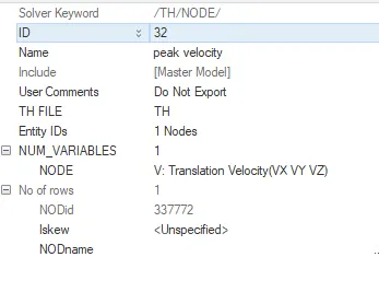
-Select the node in Entity IDs which one given in the question.
-Node - Translation velocity (vx vy vz).
13. Time step to run time:
- Go to solver>Engine_keywords>DT
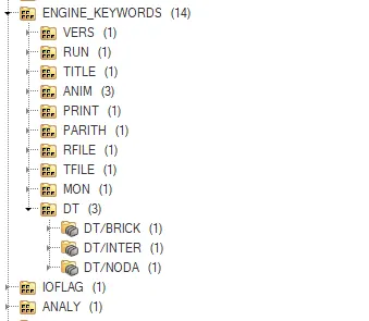
-select the Dt/ Brick,inter,noda
scalefactor min Time step
Brick 0.9 1e-4
Inter 0.6 5e-4
Noda 0.6 5e-4
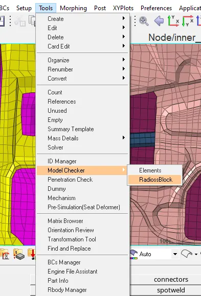
14. Model Checker:
-Go to Tools>model checker>Radioss block.
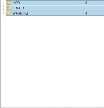
-Run the model checker.
-No error .
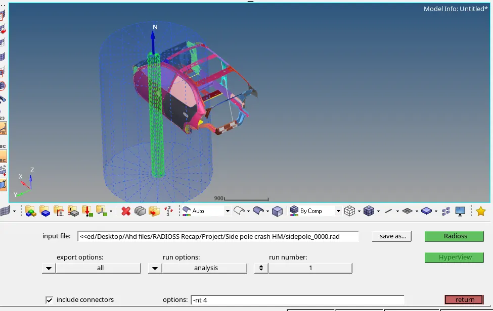
15. Running the Analysis in Radioss
-Go to analysis>Radioss>radioss.
16. Analysing the output file:
-Start position of energy and mass error as shown below.
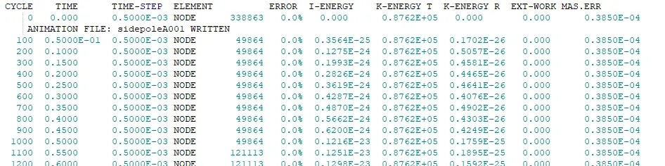
- Complete the simulation check the energy and mass error as shown below.

-Energy error: 0% to -1.7%.
-Mass error : 0.3850E-04 to 0.4003E-04
-Elapsed Time = 6729.57 s
1:52:09
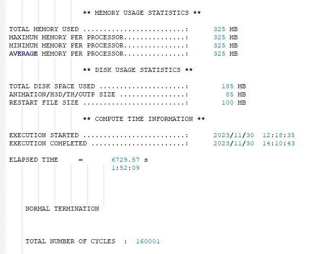
- Then open hyperview and upload the h3d file
-Get the simulation file .
17. Hyperview:
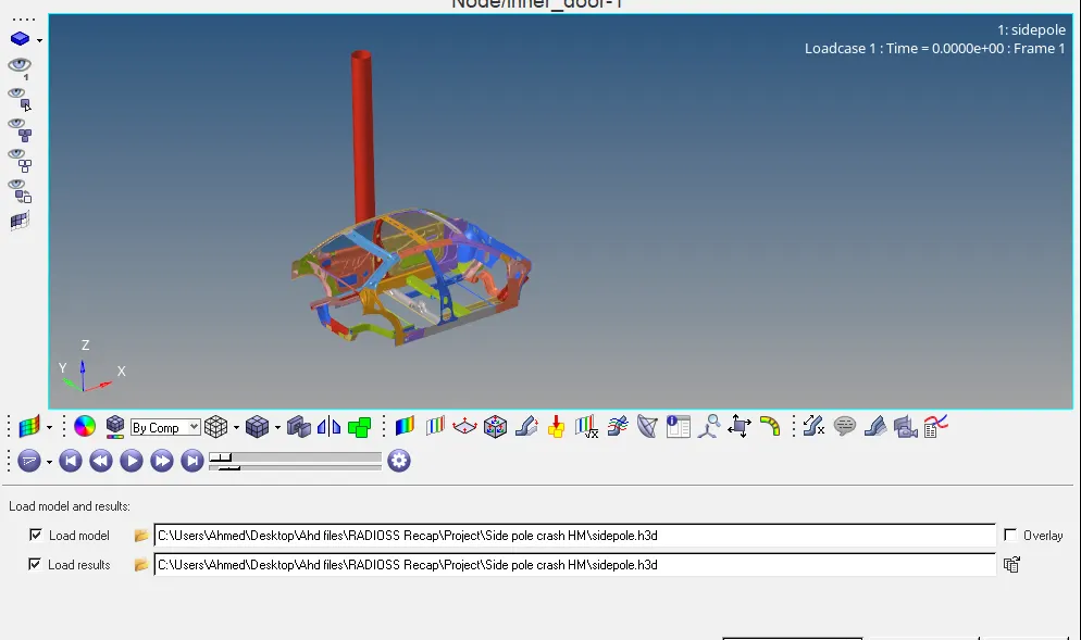
-observe the displacement.
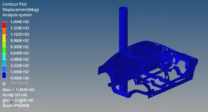
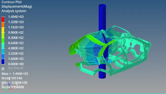
- In above the crash simulation of vehicle, we can see th vehicle is impacting on the pole.
-After the impact frame of the vehicle is deform and vehicle body contracted around the pole of B_pillar point.
-We can see the deformation around the pole.
18. Hyper graph:
-Open the Hyper graph and upload the TO1 file .
Global variable Energies:
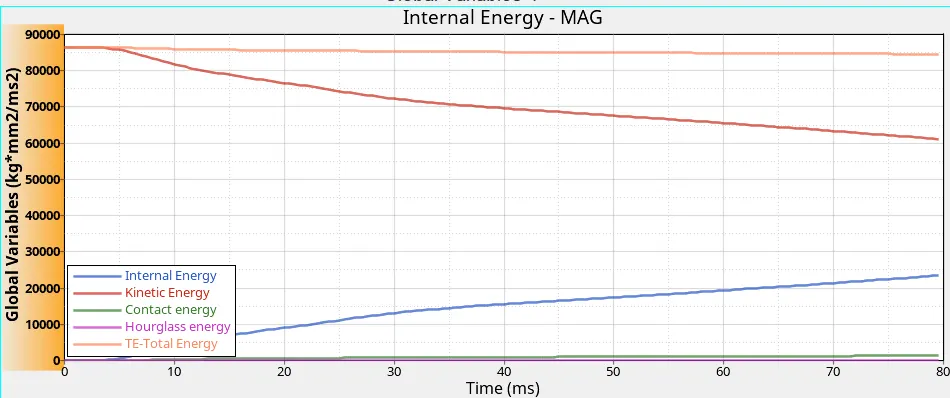
-We can see the kinetic and internal energy changes.
-BIW lossed the kinetic energy throughout the simulation due to decrease the velocity.
-At the same time observe the force and the result is incresing the internal energy.
Rigid wall Forces:
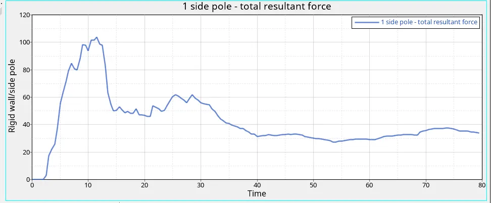
-Rigidwall force is generated zero first 3ms of simulation because of no contact.
- After 3ms sudden peak of graph becasue vehicel contact the rigid wall .
-It reach max in 10 t0 12 ms.
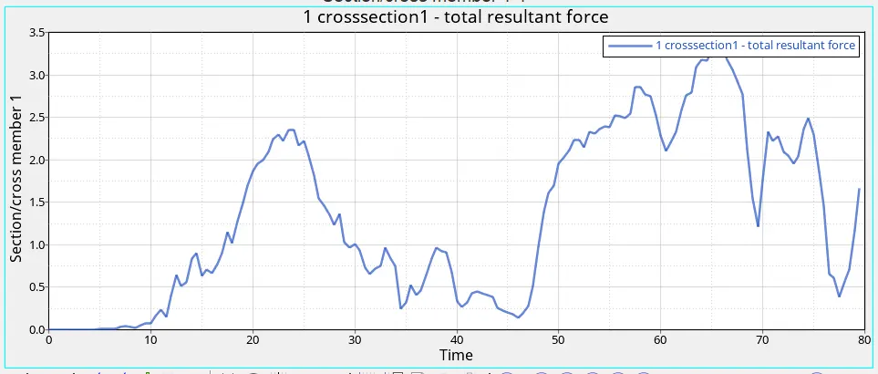
Sectional force cross member 1:
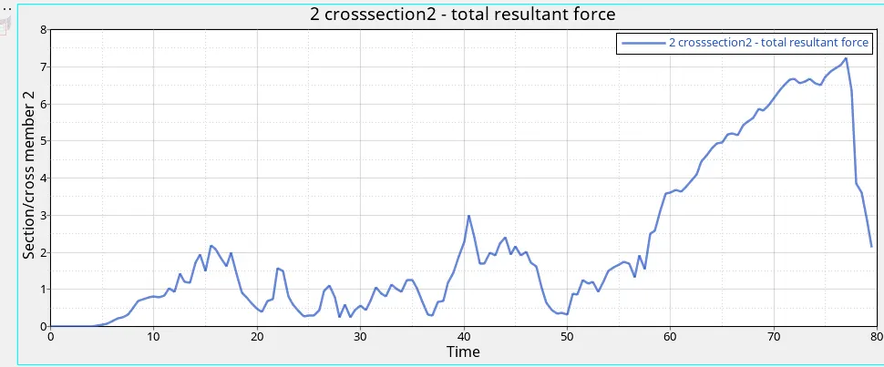
Sectional force cross member 2:
Peak velocity of inner door:
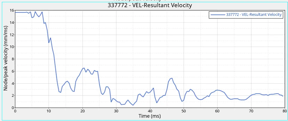
-As per the graph, the peak velocity of the node on the door 15.94mm/ms.
-The velocity of the node is almost constant before hitting the rigid cylinder pole upto 2ms.
-After the impact there is a huge drop and then small rise due to fold deformation.
-Time passes, velocity drecease gradually.
Intrusion of fuel:
Intrusion Of B pillar:
-Intrusion of Hinge:
Result & Conclusion:
-Side crash analysis carrired out on the given model car as per requirment.
-The output requests were also generated after the creation of cross-section in each of those region.
-Fuel tank intrusion in general could be reduced by using anti-intrusion beam between the pillars.
-They increase the rigid of the door and distrubute the energy event of the side crash.
-The side crash analysis go through standards FMVSS and learn about the loadpath, intrusion and crash parameter used.