Assignment 7-Side Pole Crash Simulation Challenge
Objective:
To perform a side crash with the help of a given car model. To obtain the results as mentioned in the above question, the following steps should be followed.
- Check the unit system and either follow [Mg mm s] or [Kg mm ms].
- Create an appropriate interface, friction 0.2, and recommended parameters.
- Make sure of no penetration and intersections.
- Create a rigid pole with a friction of 0.1 as per the FMVSS 214 standards.
- Compare the model weight with the reference model and use added masses to reach the target weight of 700kg while getting CG about the required range.
- Initial velocity - 20mph, as per the standards.
- Use a model checker to ensure good quality.
- Timestep:0.5 to 0.1 microseconds.
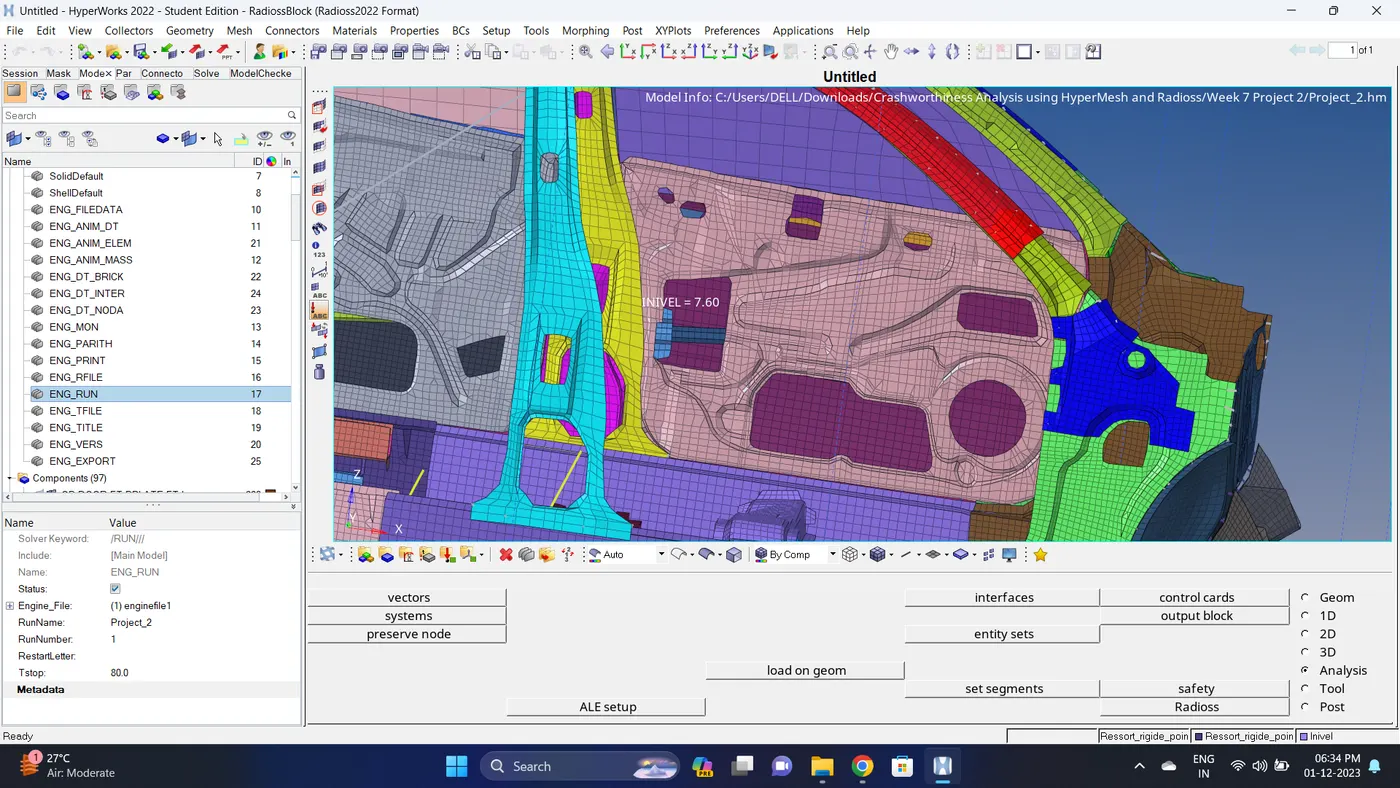
- Run 80ms.
Output requests
- Sectional force in the cross member.
- Intrusion at B pillar,hinge pillar and fuel tank region. Provide recommendations on what can help to reduce Fuel tank intrusion.
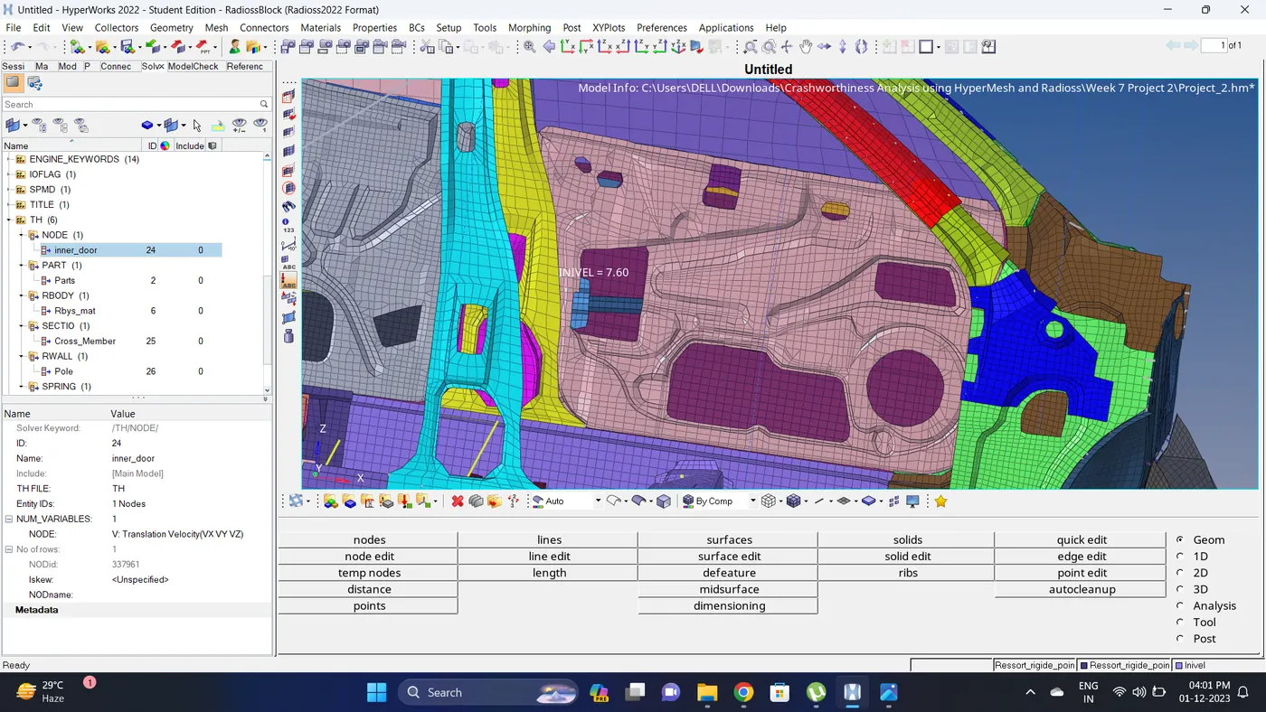
- Peak velocity of an inner node of the door.
Procedure:
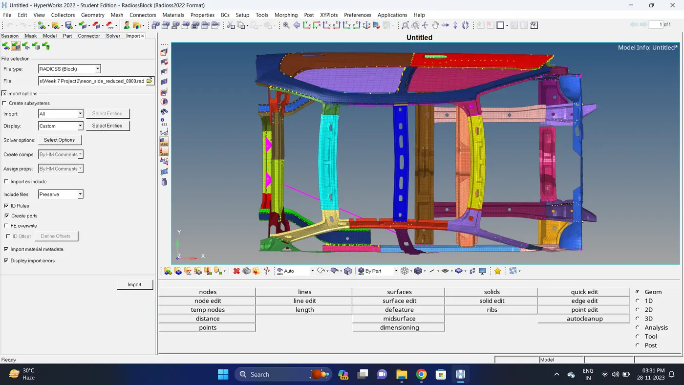
1. Import the neon_side_reduced_0000.rad file.
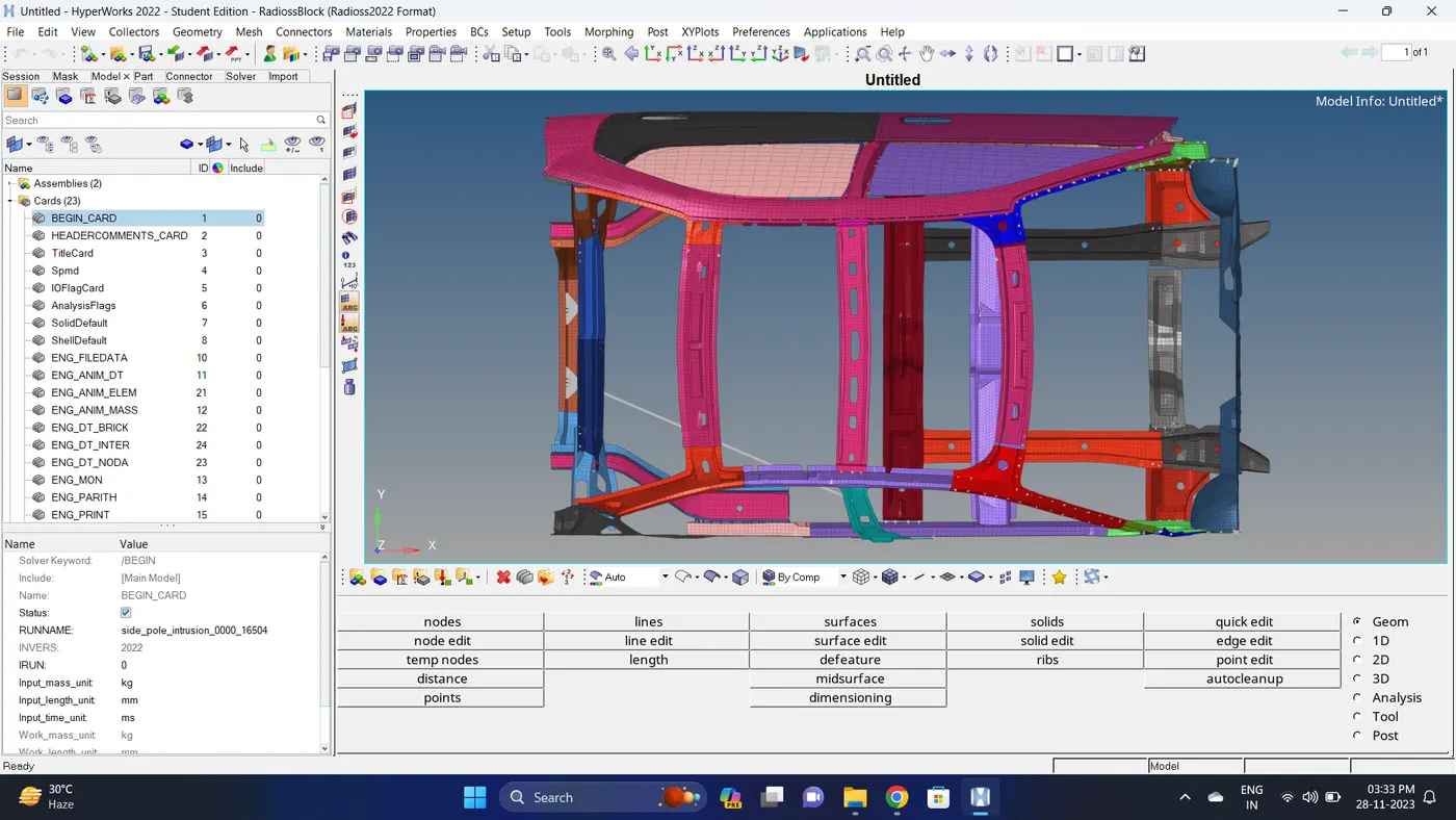
2. Go to Model deck - Cards - BEGIN_CARD and Check the unit system.
The unit system is kg - mm - ms.
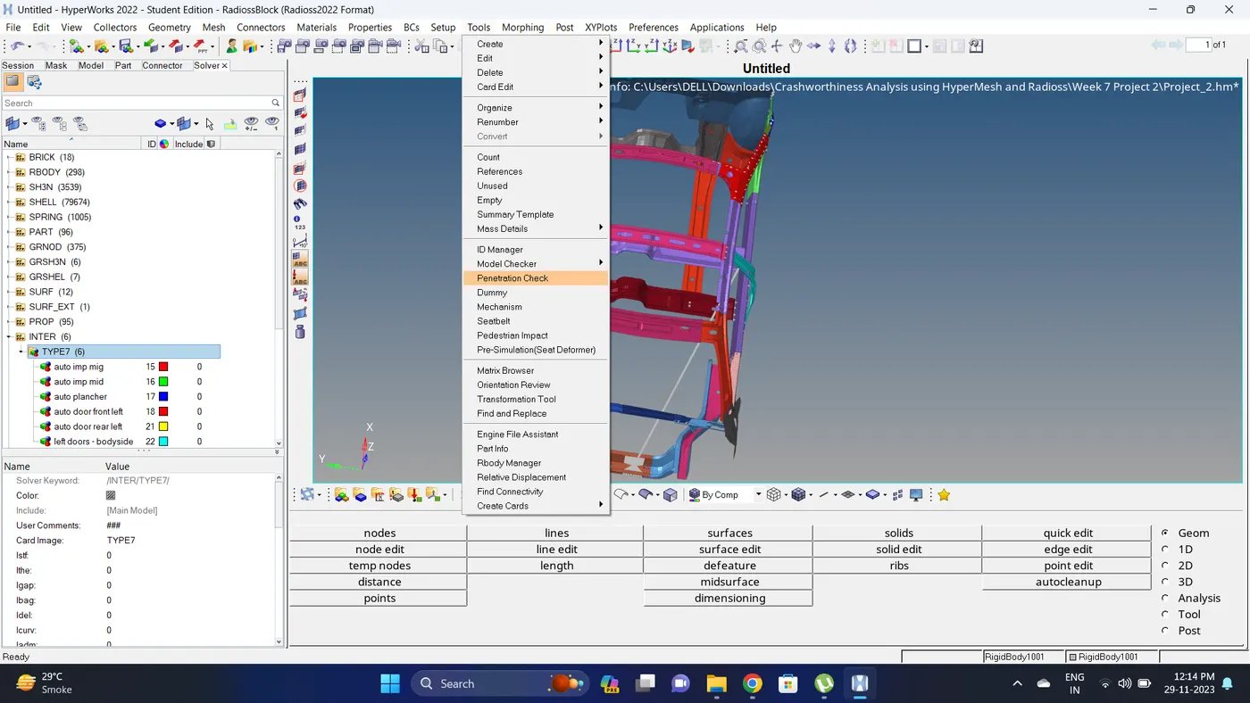
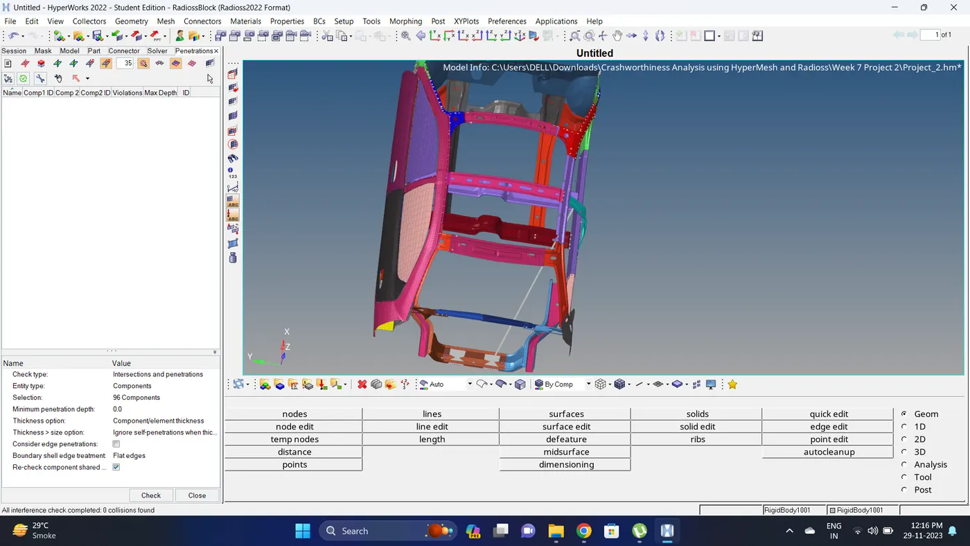
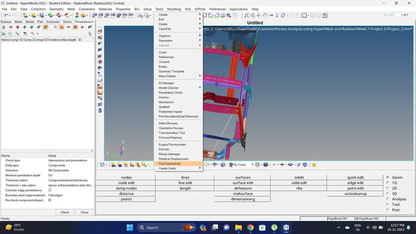
3. Check the intersections and penetrations.
Go to Tools - Penetrations Check - Select the components - Click on Check.
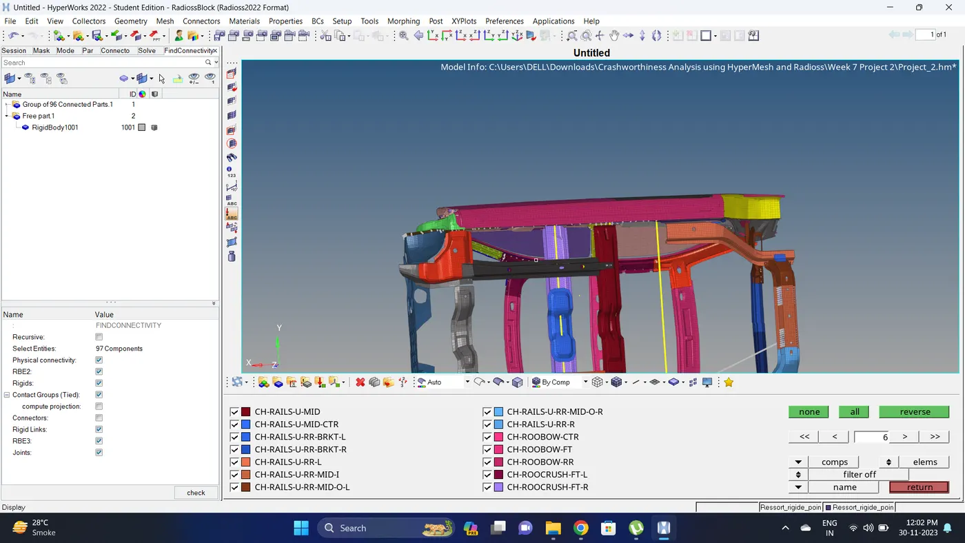
4. Find Connectivity of all the componnent. Go to Tool - Find Connectivity - Right click on blank deck - Click on Find Connectivity - Select all the component - Click on Check.
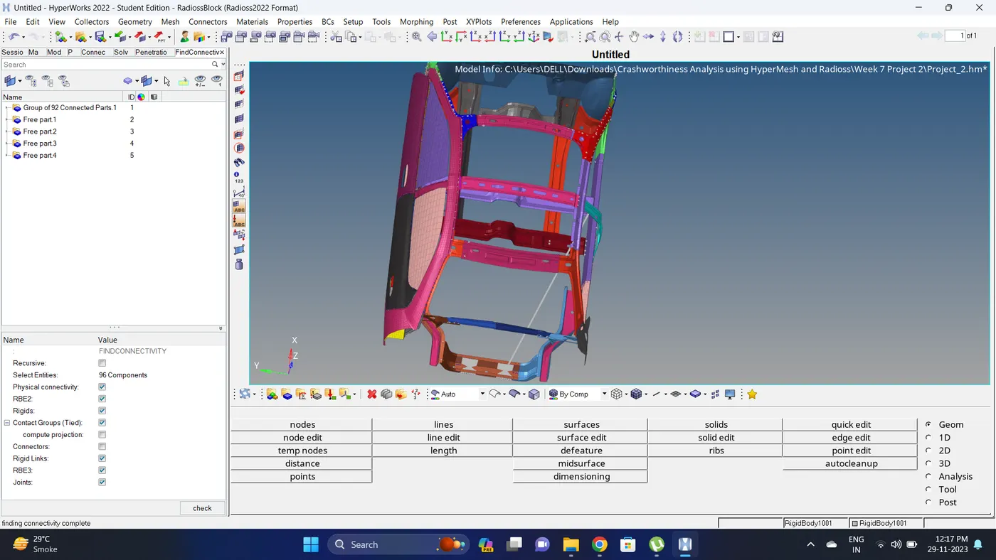
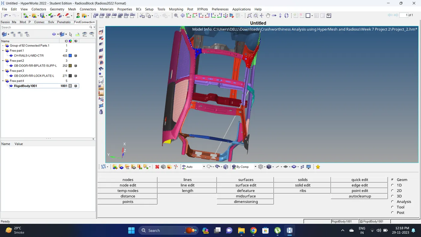
5. Make connection component card to current.
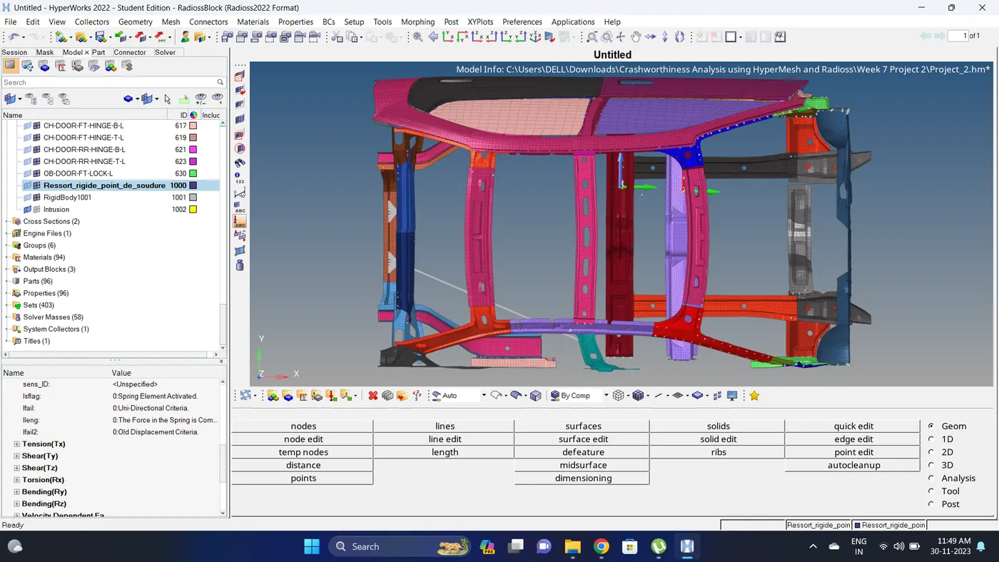
6. Firstly visible only the component which has to create a rigid connection. Go to 1D - rigids - select nodes and click on create.
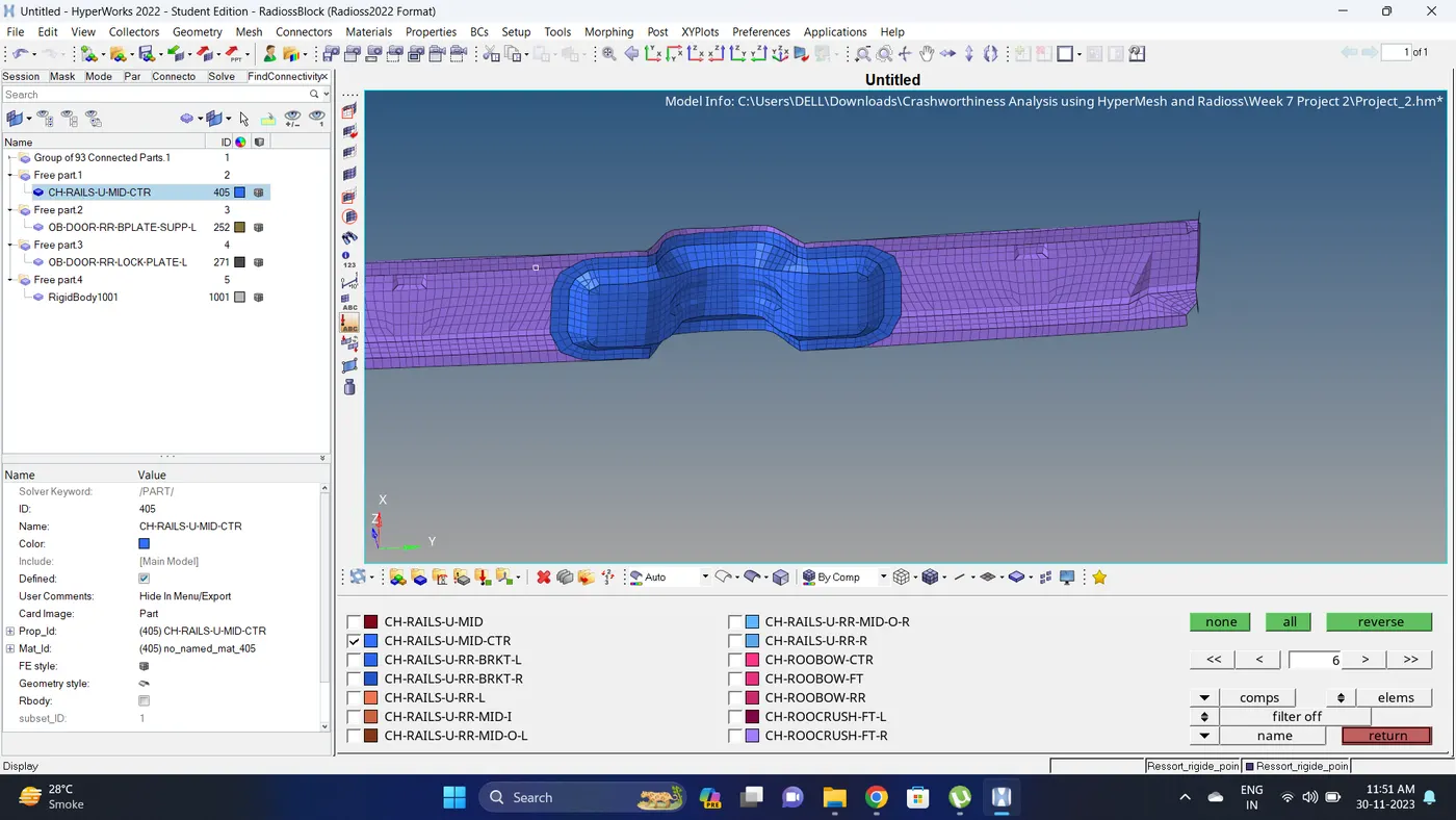
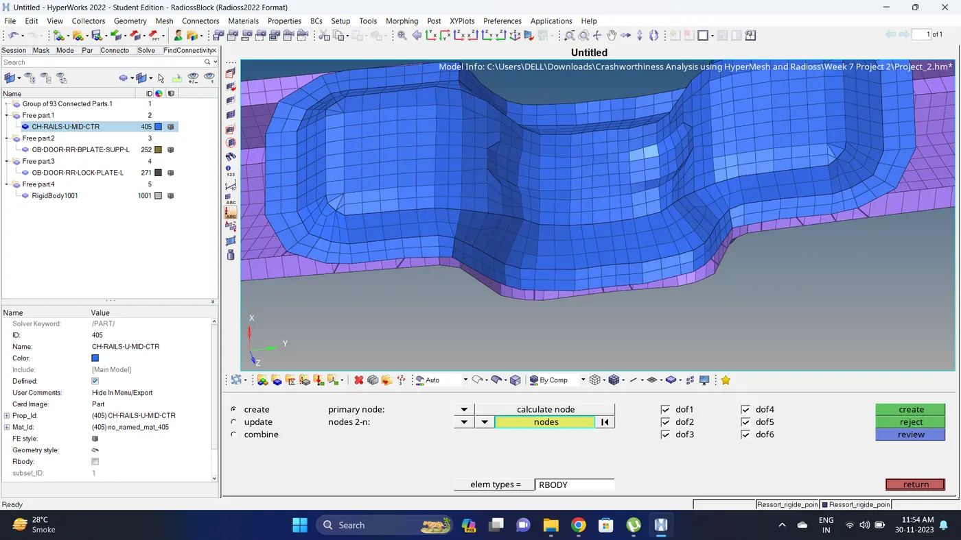
7. Do the same for all the other components also and Check for the Connectivity again.
Note: Since in this model some components are not present that why RigidBody1001 showing.
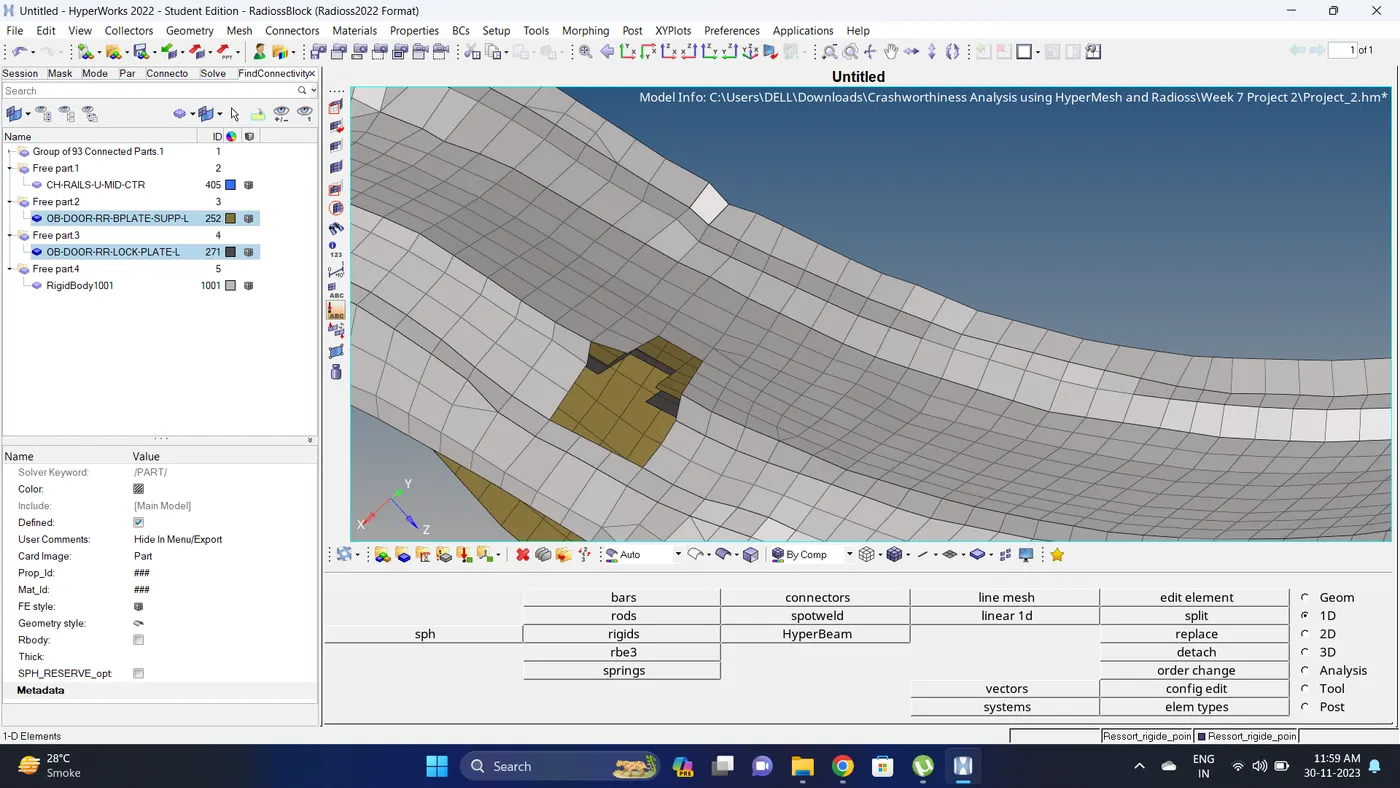
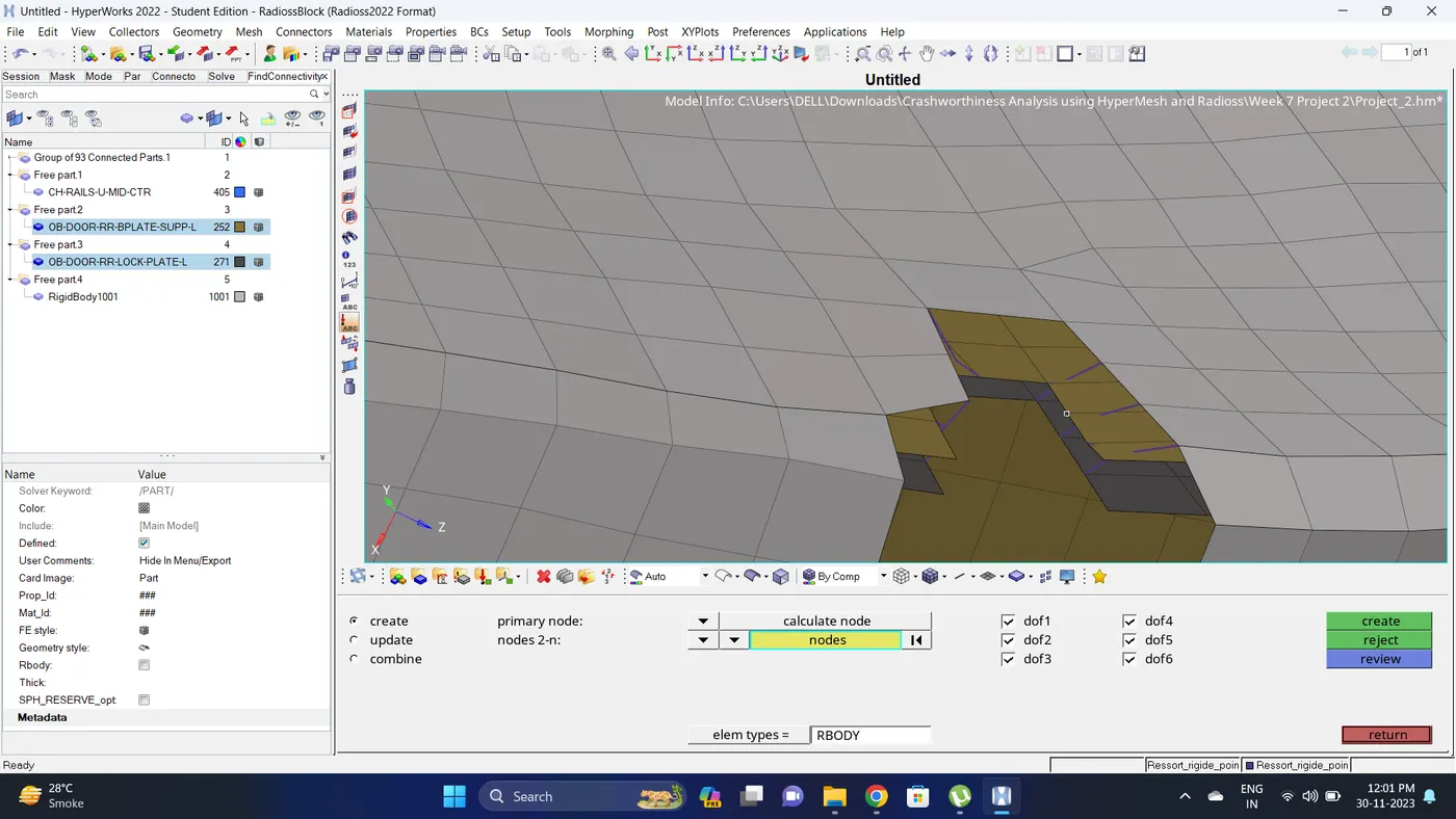
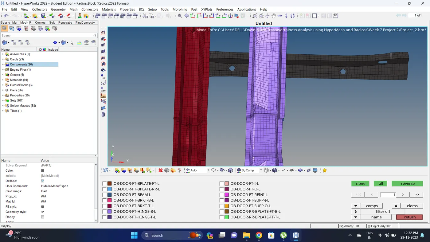
8. Isolate the component in which sectional force is to be calculated.
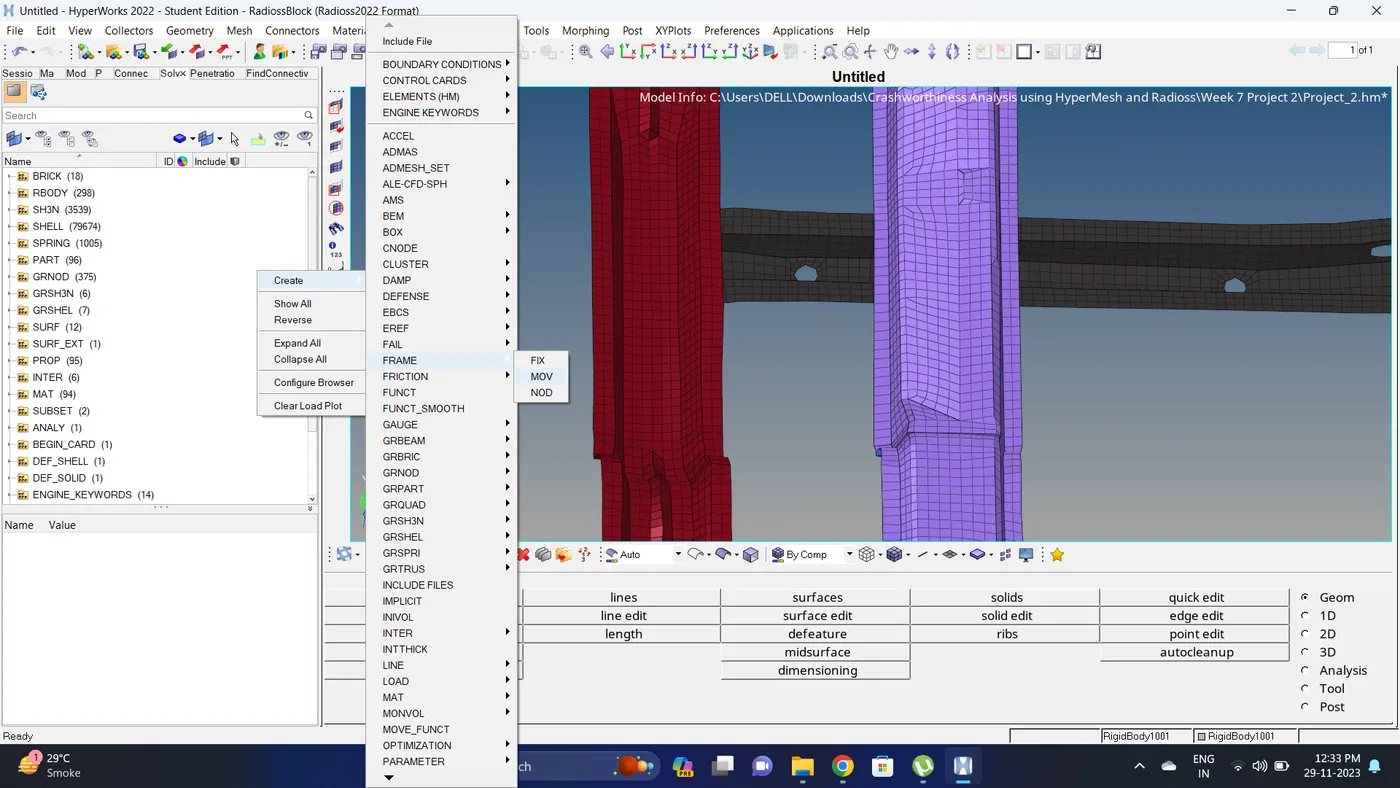
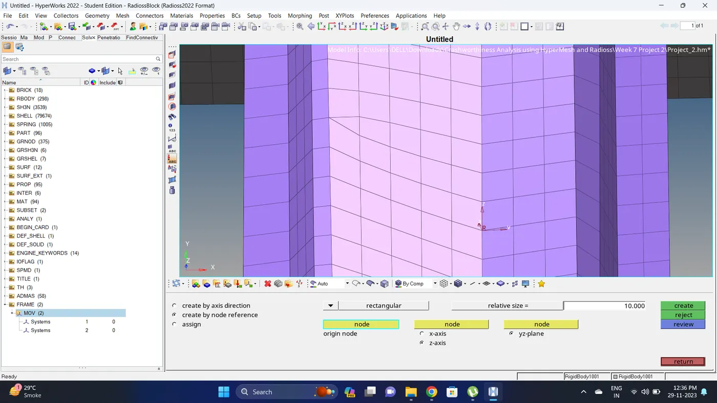
9. Create a moving frame. Go to the solver deck - right click - create - FRAME - MOV - Select the co-ordinate - click on Create.
Note: While creating the moving frame keep the Y-axis toward the crashing direction.
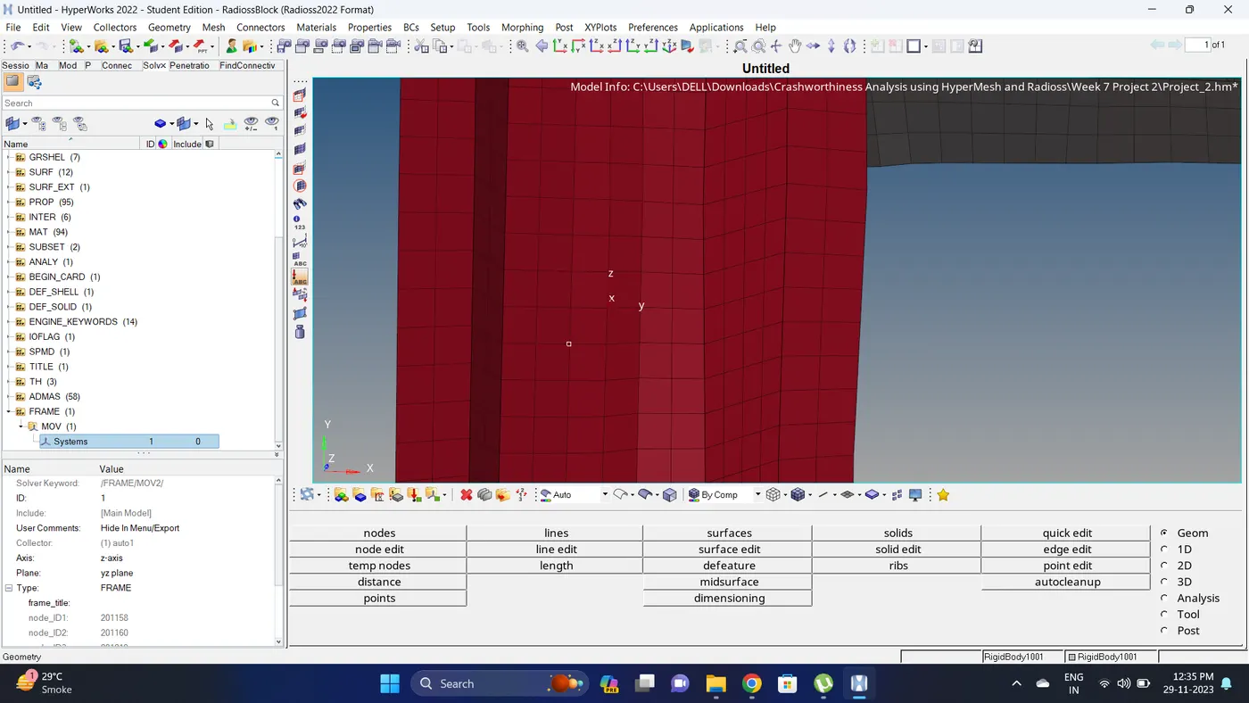
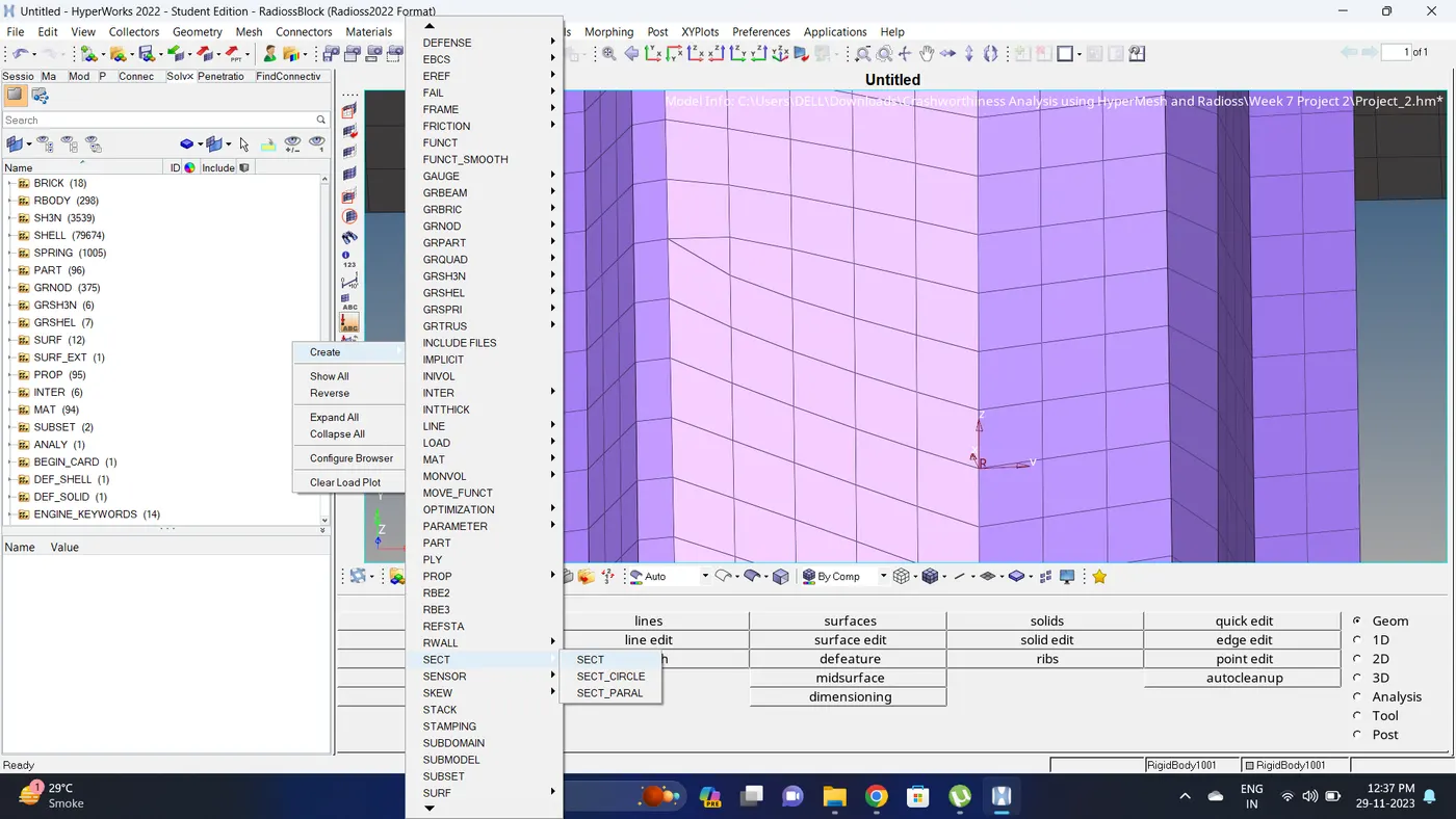
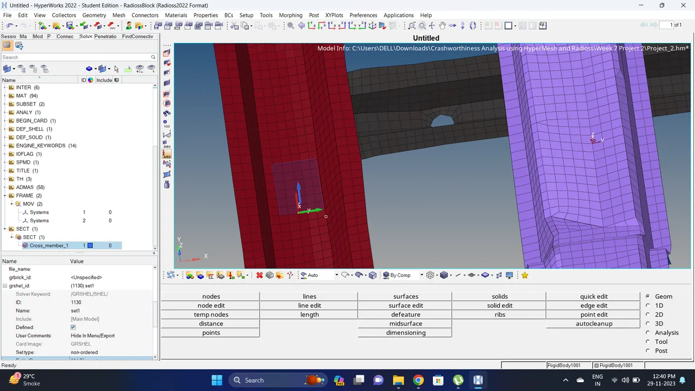
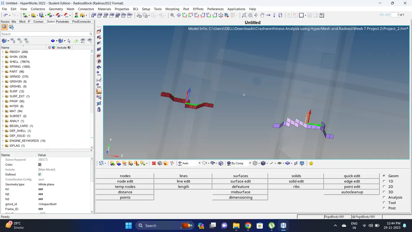
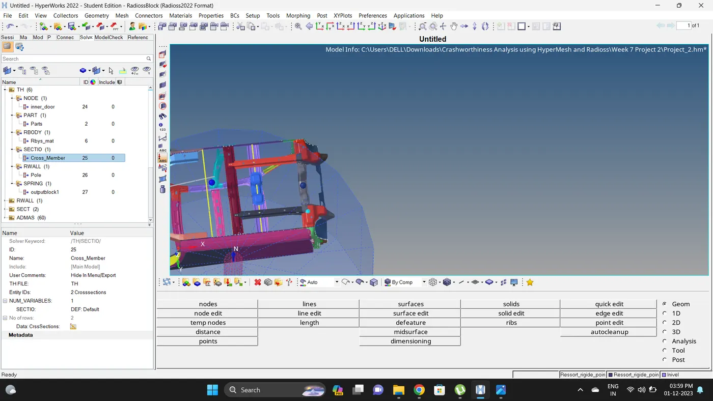
10. To create a section Go to Solver deck - Right click - Create - SECT - SECT - Change the name - Select N1, N2 and N3 Node - Select Shell group identifier element (grshel_id) - Select the Frame_id.
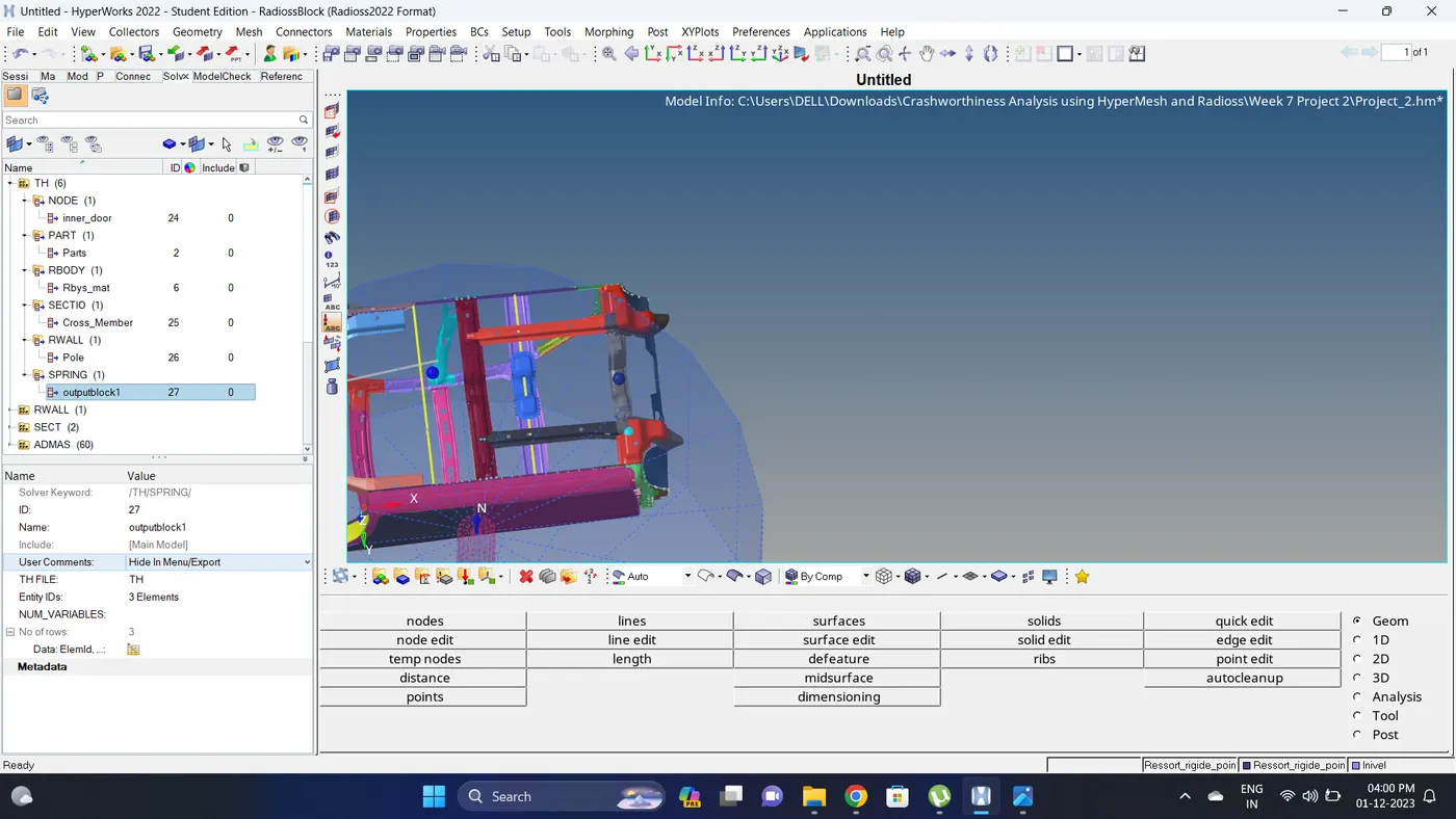
11. To create a Intrusions at Hinge Pillar first create a new component - go to 1d - springs - select nodes (2 nodes should be on a straight) and create a spring.
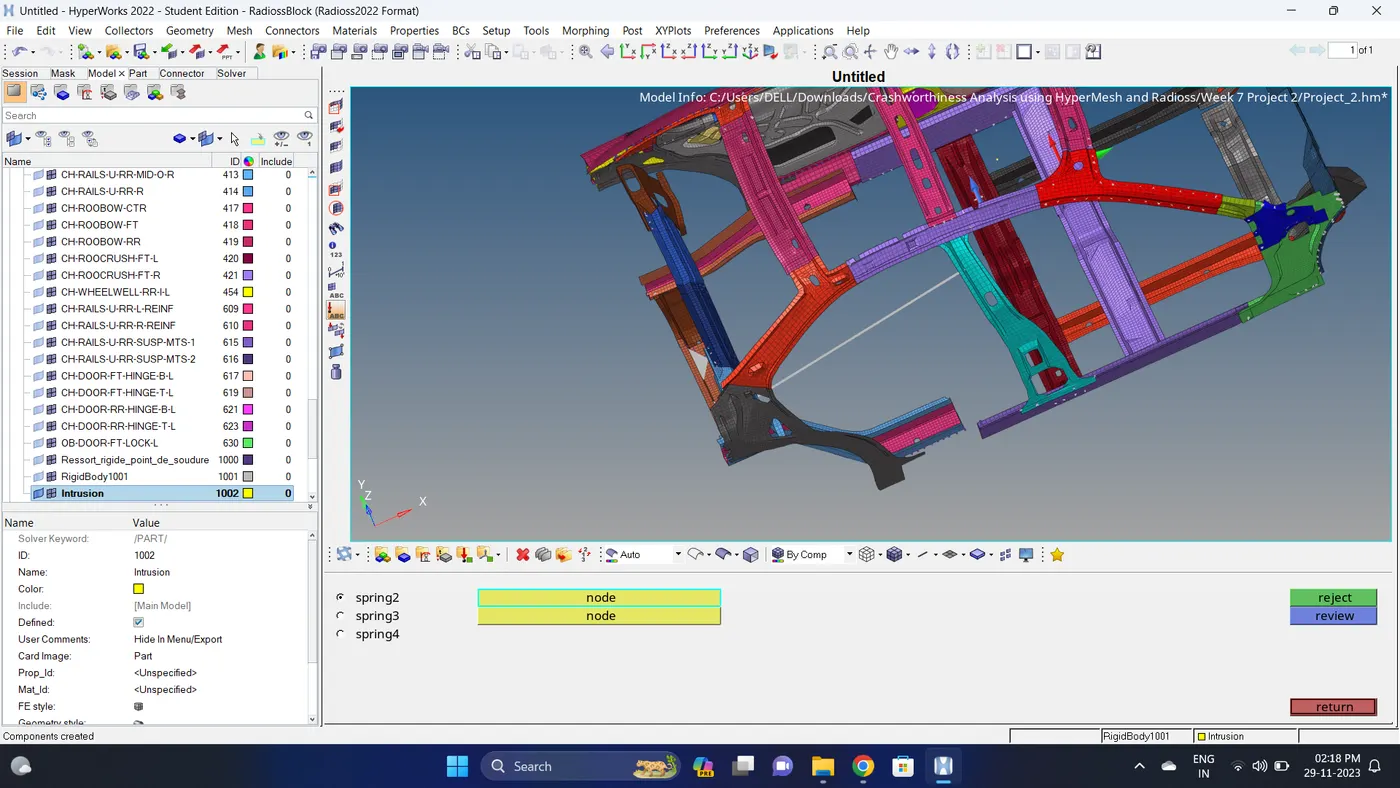
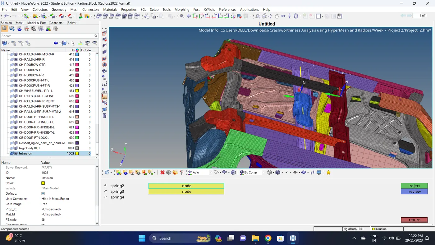
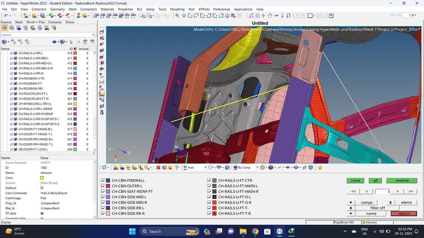
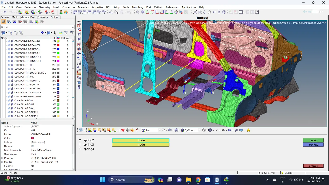
12. Similarly create a spring element for the Fuel Tank and B Pillar.
Note: Node is selected on the Rocker.
13. Create a property for spring and assign it to the component.
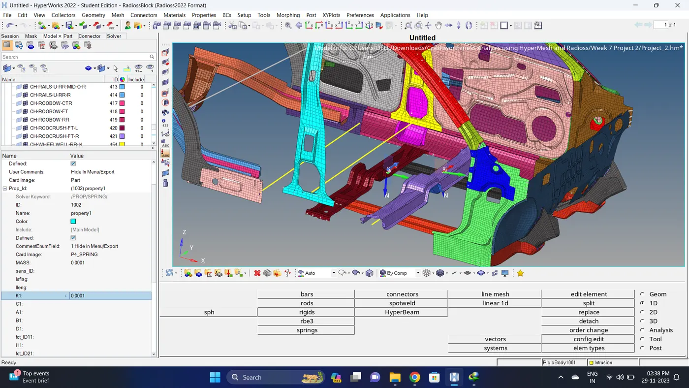
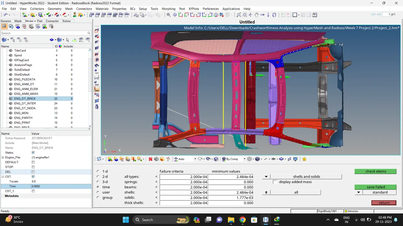
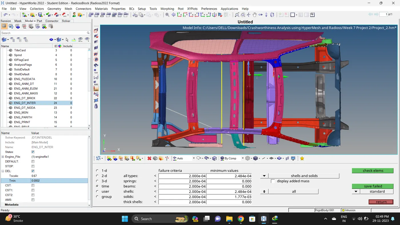
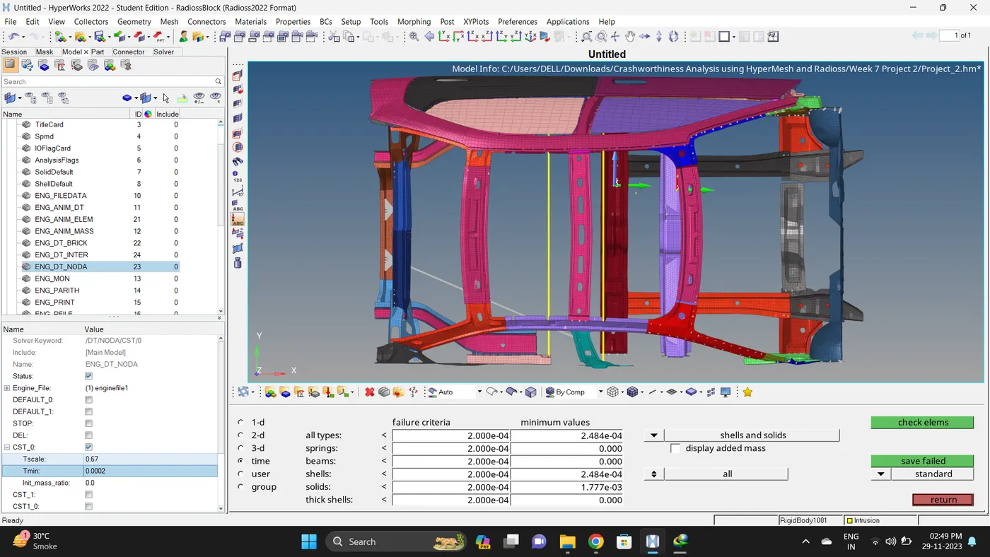
14. In Model deck - Cards - In ENG_DT_BRICK, ENG_DT_INTER AND ENG_DT_NODA change Tmin to 0.0002, 0.0002 and 0.0002.
Note: For checking the time step value go to Tools - Check element - time - give value and test the time step for different elements.
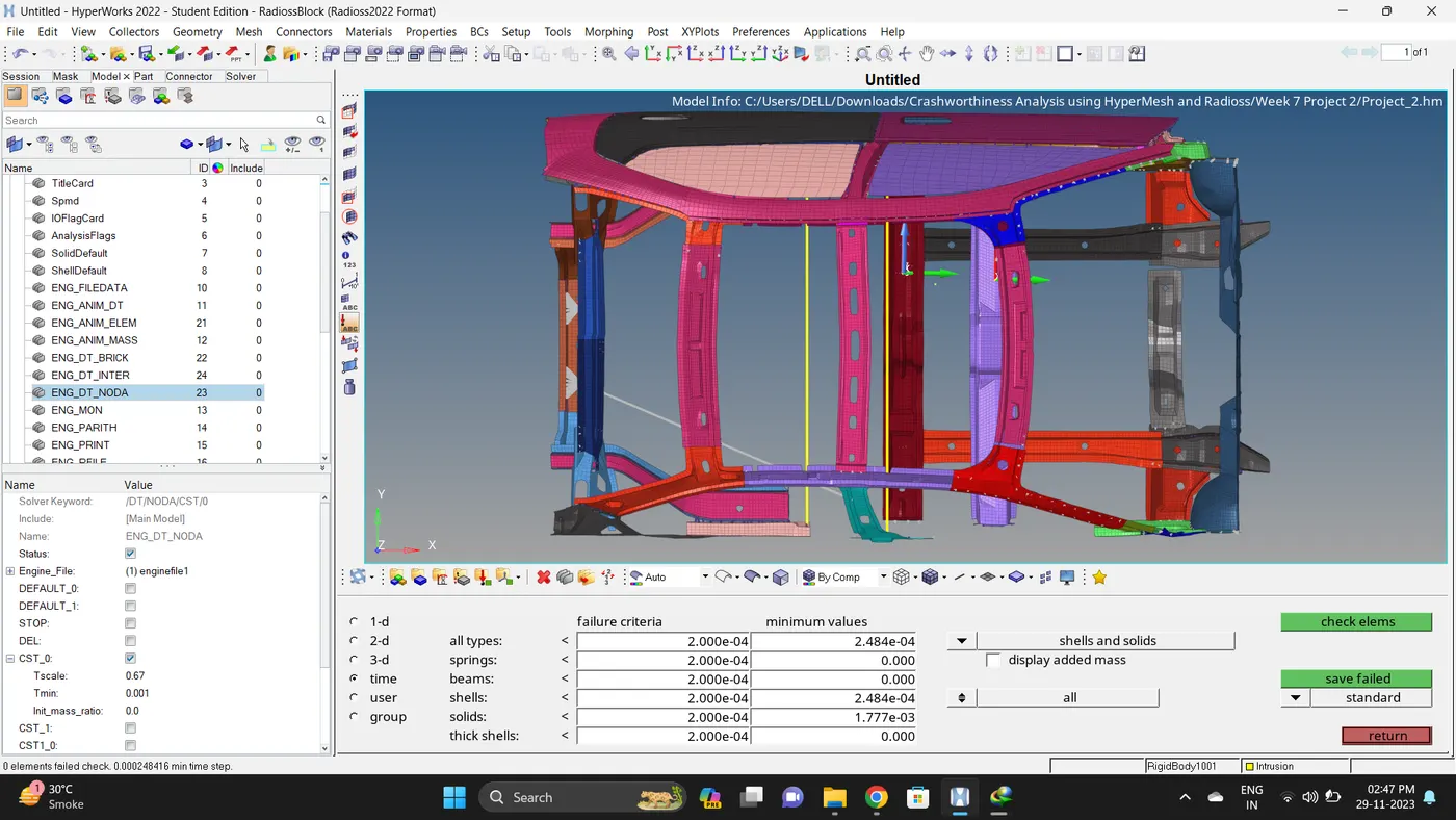
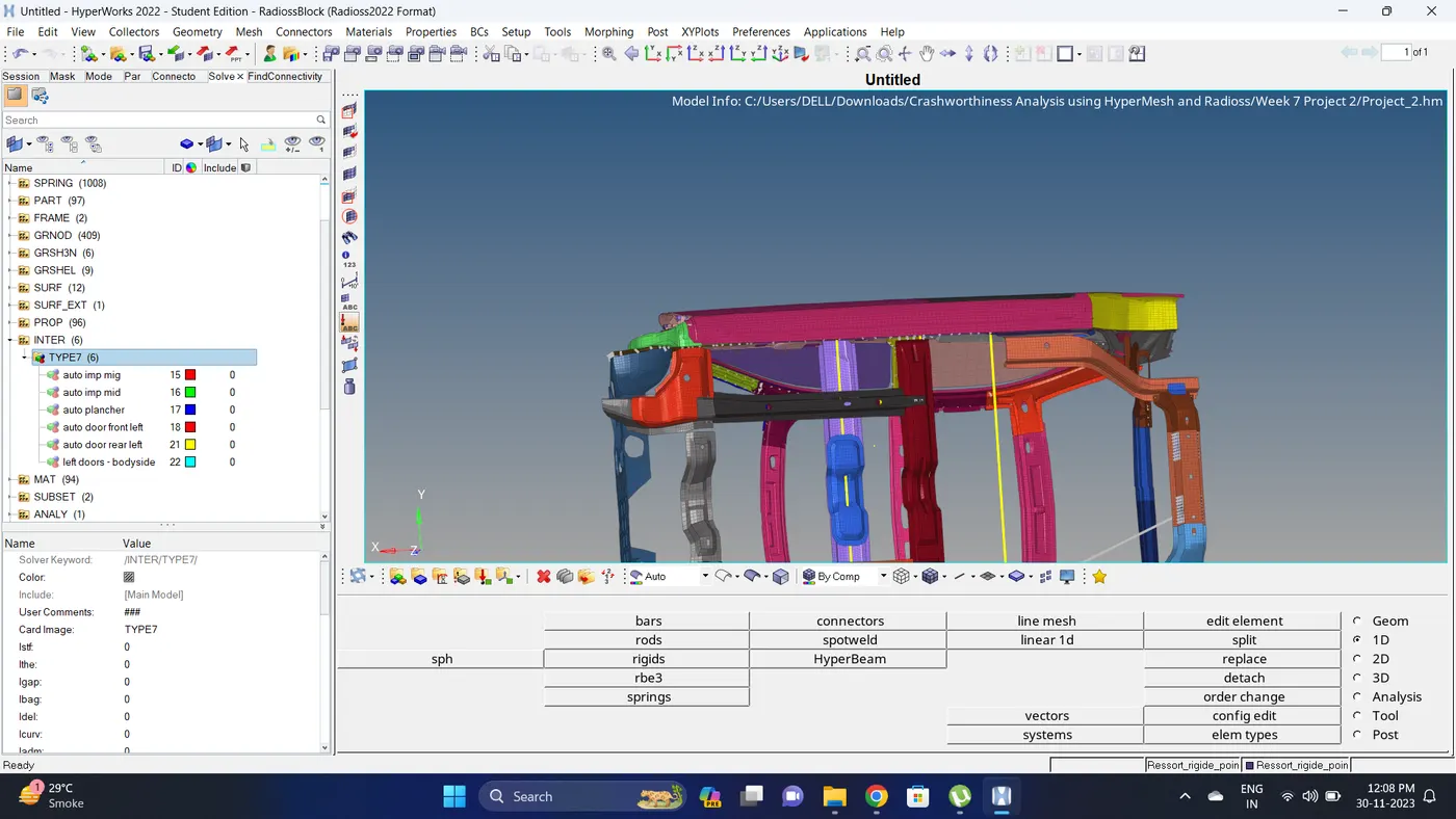
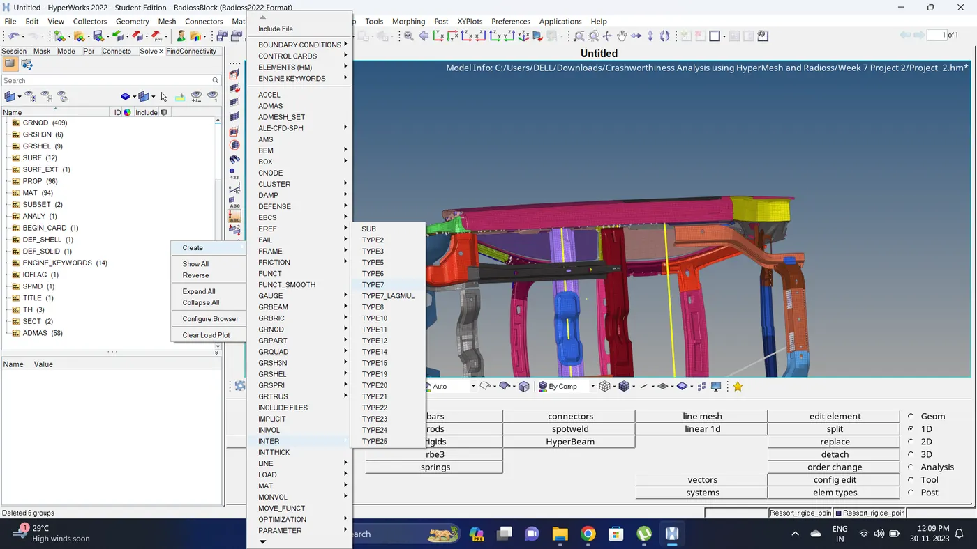
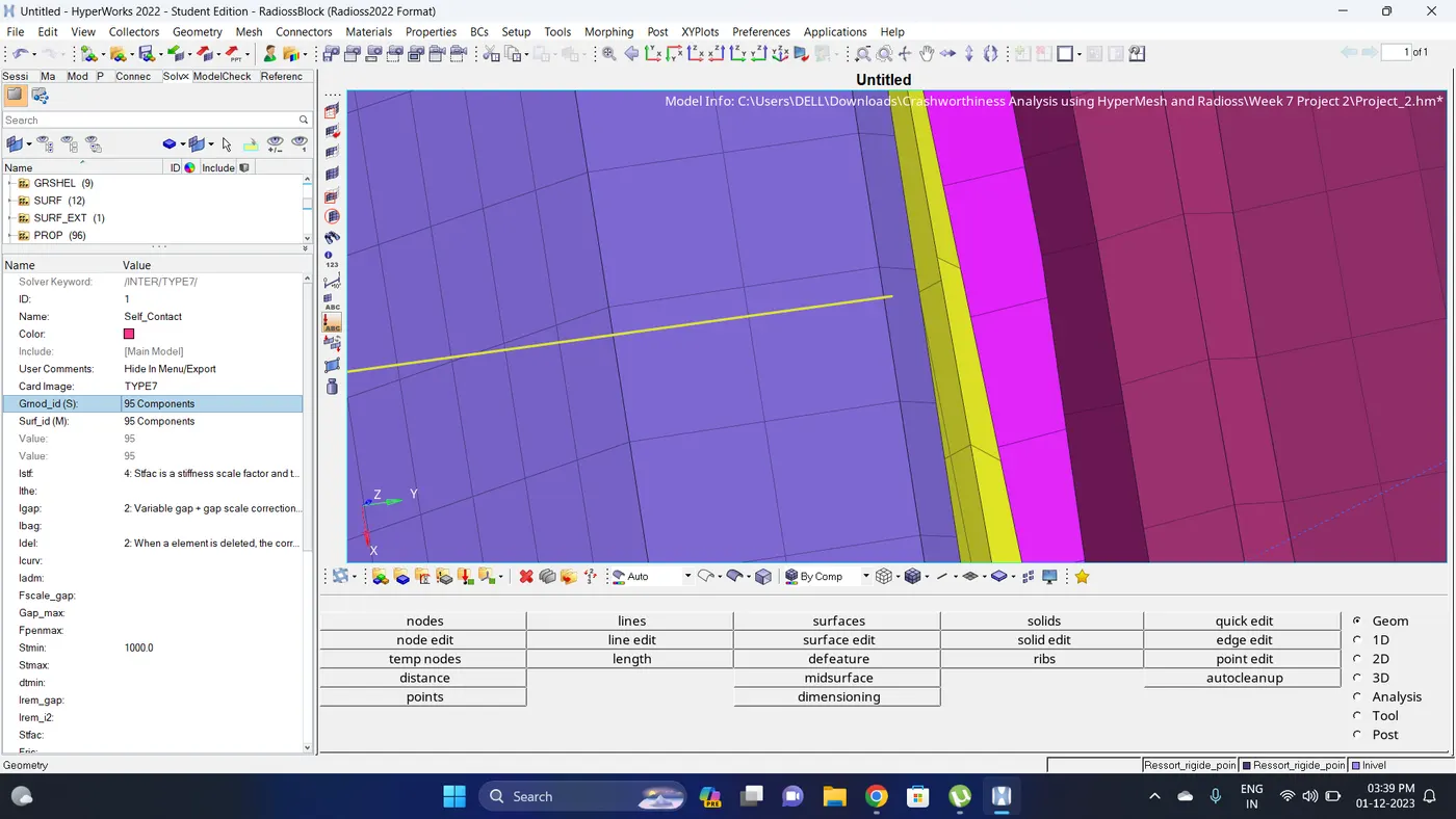
15. Delete Previous Interface and Create a TYPE7 self contact interface. Go to Solver deck - Create a new TYPE 7 INTER - Select nodes and elements - give parameters.
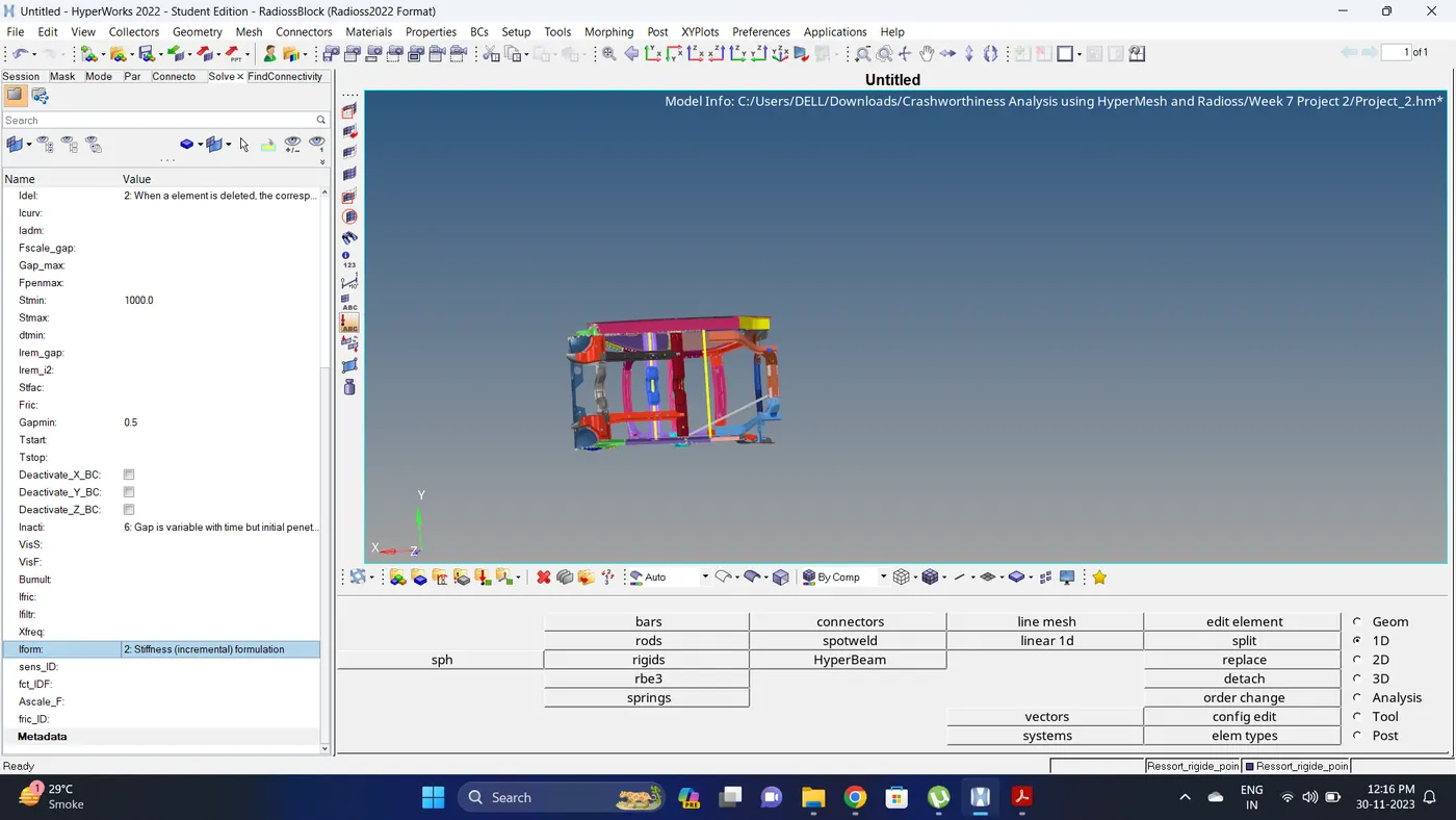
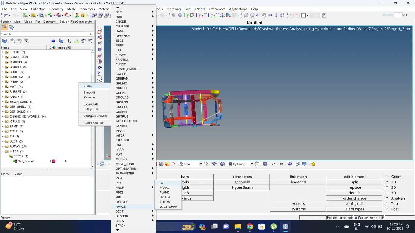
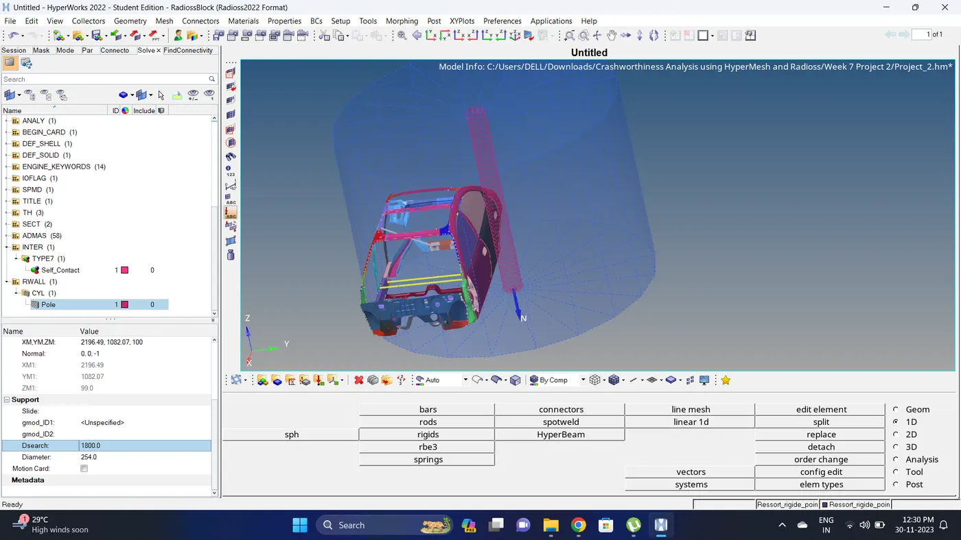
16. Create a Rigid Pole.
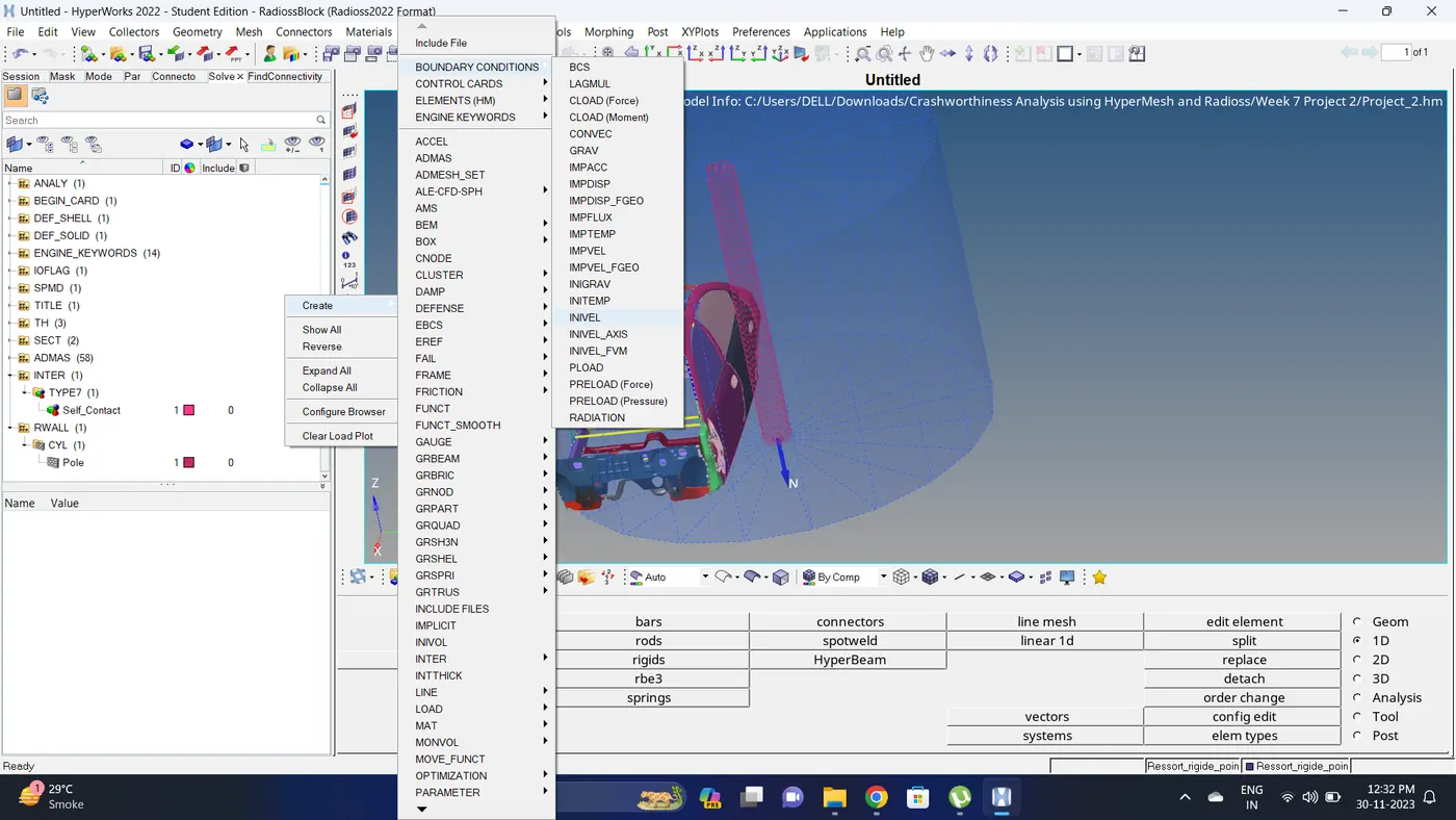
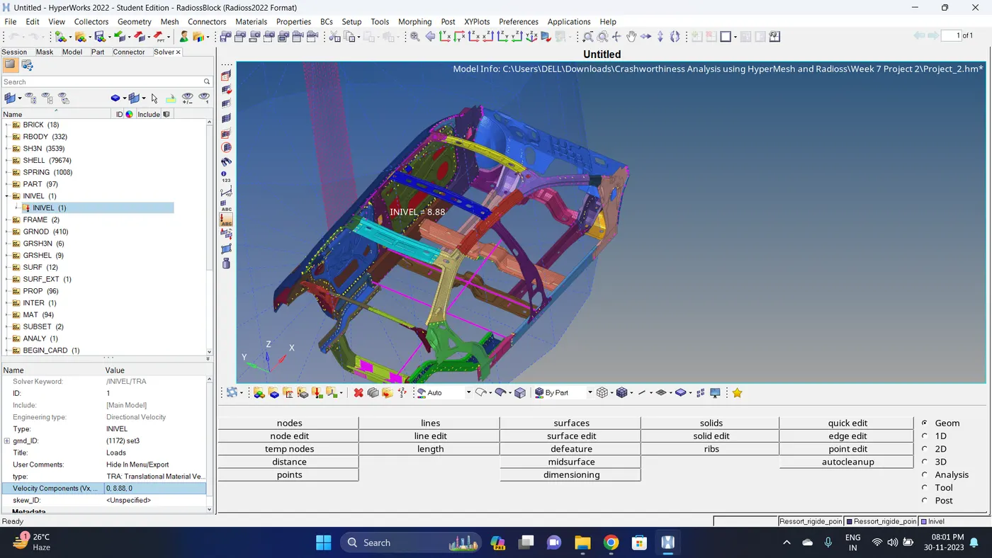
17. Create a Initial velocity. Go to Solver deck - Right click - BOUNDARY CONDITION - INIVEL - Give initial velocity - Create a new grnd_ID - Select nodes.
Note: As per the FMVSS 214 standards the velocity of vehicle should be upto 20 mph (32 km/h).
Lets assume the velocity to be 8.88 mm/ms.
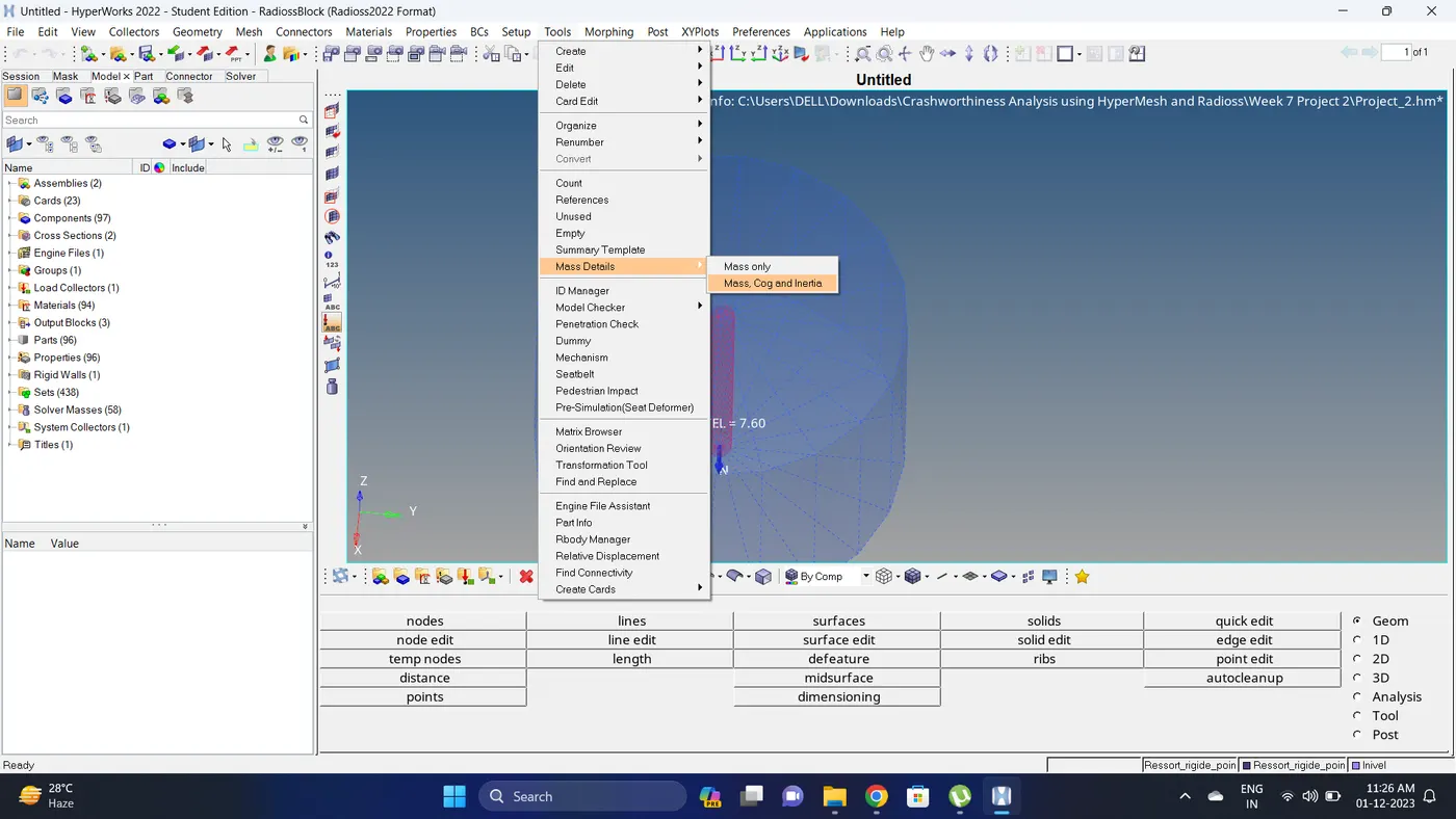
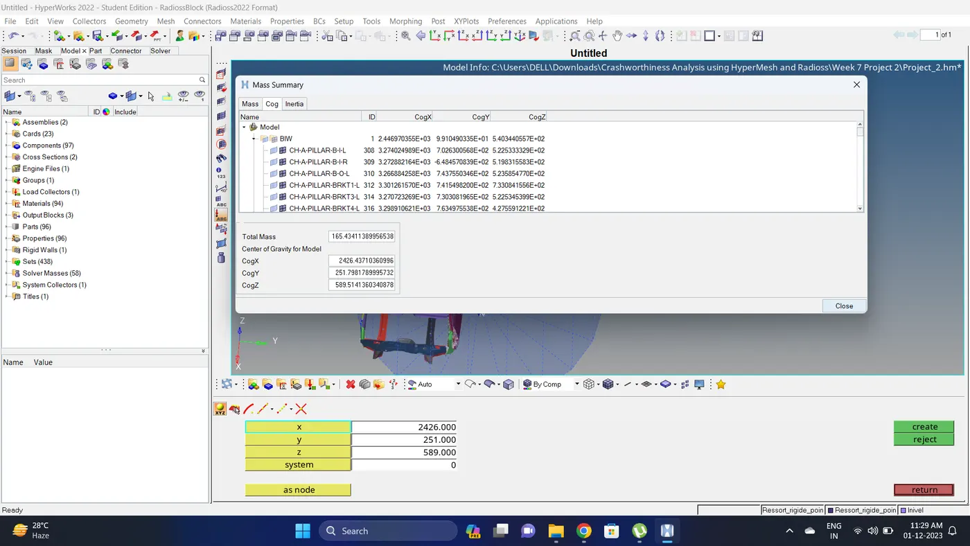
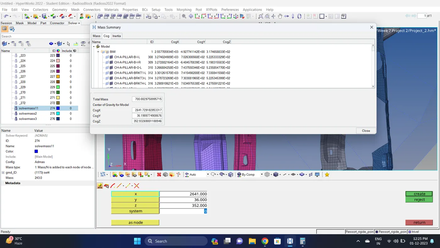
18. Check the mass and plot the COG of the model. Go to Tools - Mass details - Mass, Cog and Inertia.
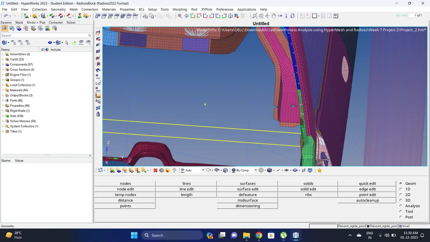
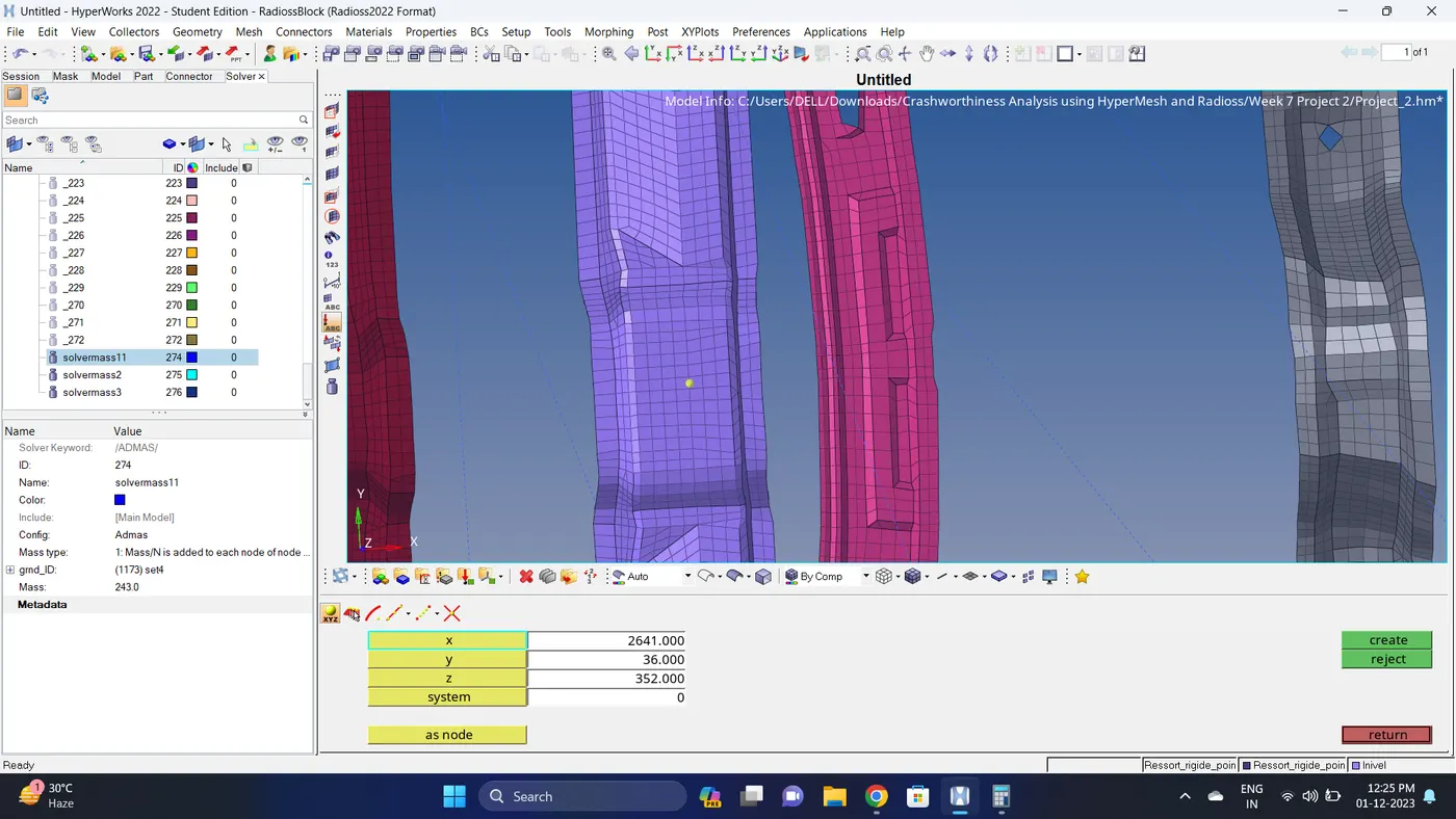
Note down the COG co-ordinates and create a node at that location. To create node go to Geom - nodes - Input the co-ordinates - click create.
19. Since model is not complete, we need to add mass to model and also align the COG of model.
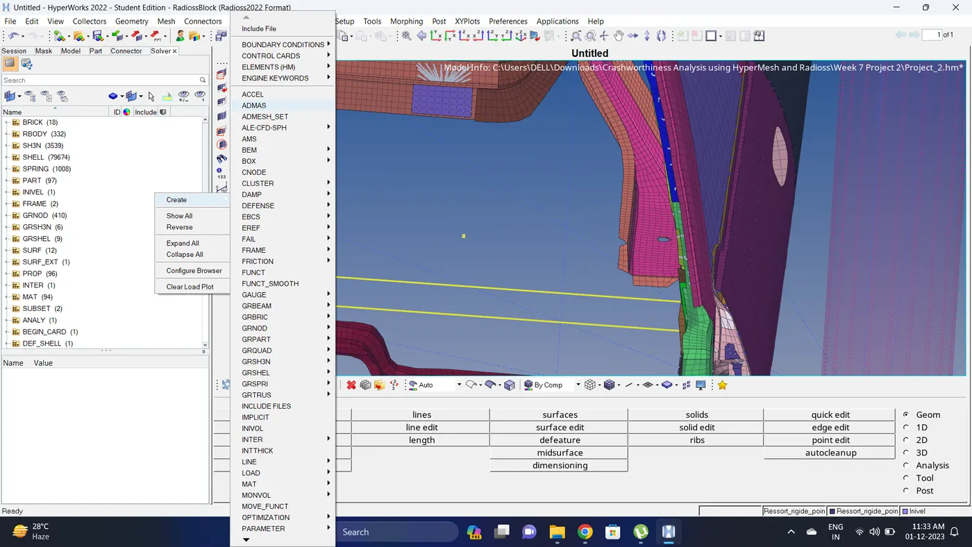
To add mass Go to solver deck - right click - ADMAS - create a node set - give mass - change mass type to 1.
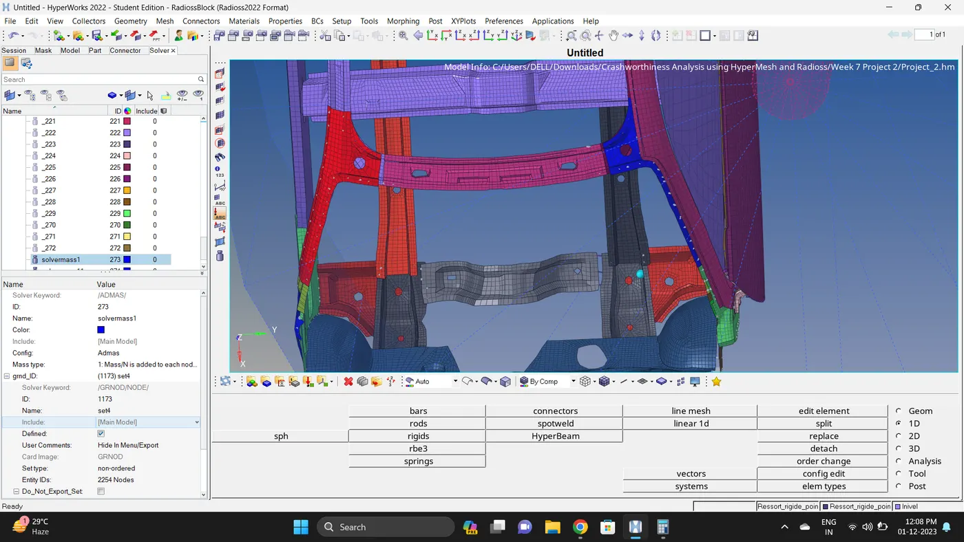
20.Add mass to the different region, so that total mass should be 700 kg and COG of the model should be near of CH-CBN-SEAT-REINF-FT component centre.
21. Create an Output request for the Sectional Forces, Intrusion and Inner node of a door.
22. Check the simulation run time.
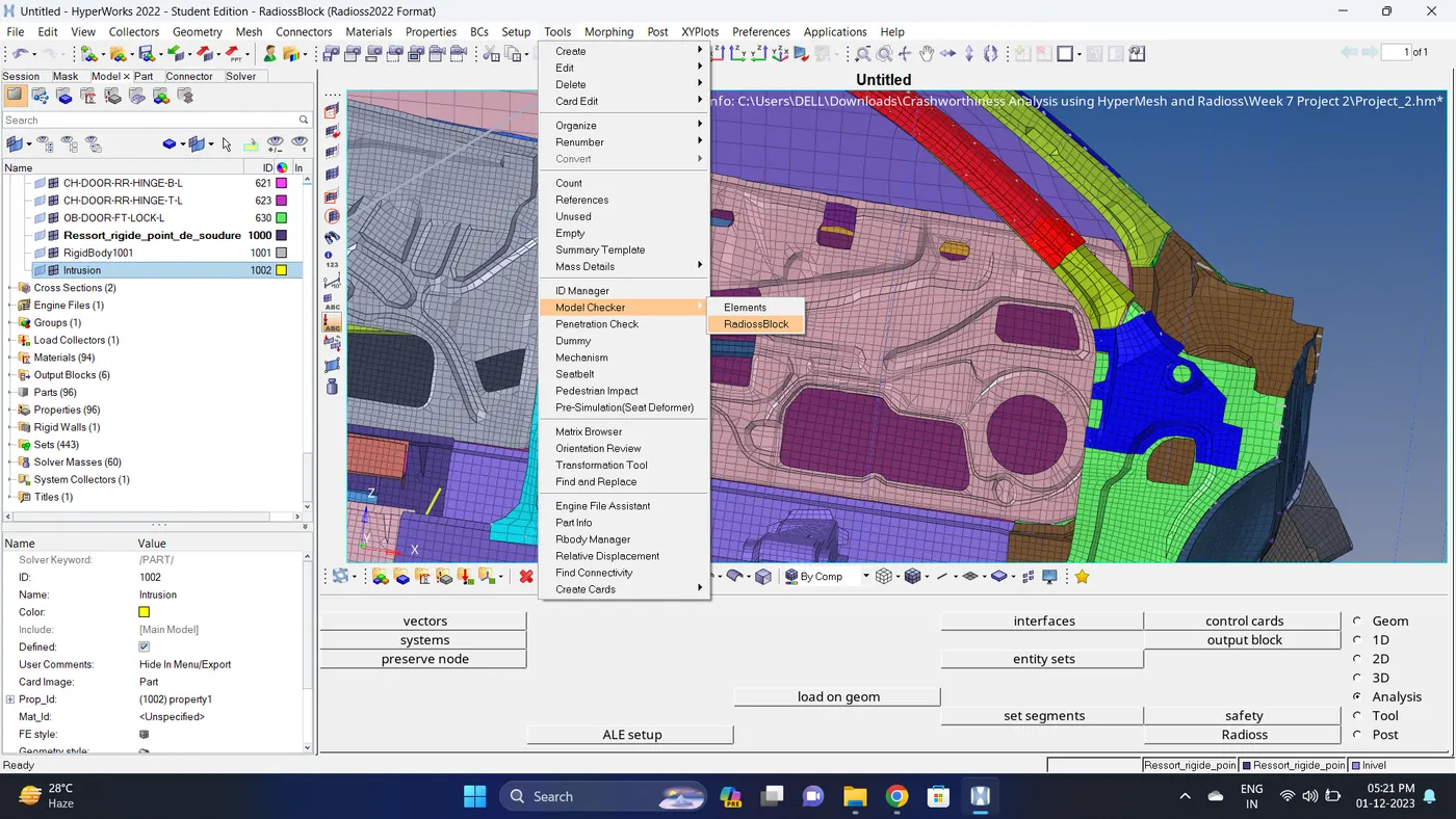
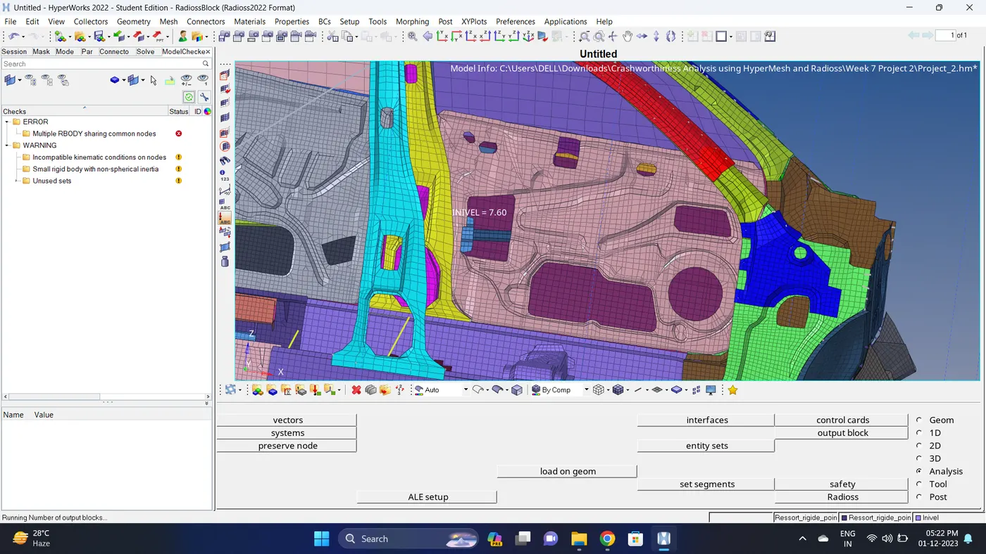
23. Run a Model Checker. Go to Tools - Model Checker - RadiossBlock - Click Run.
if there are issue fix it.
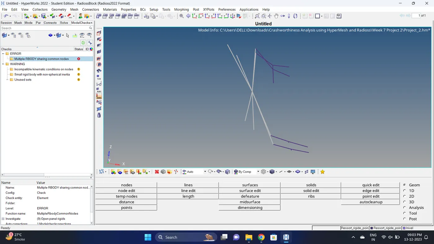
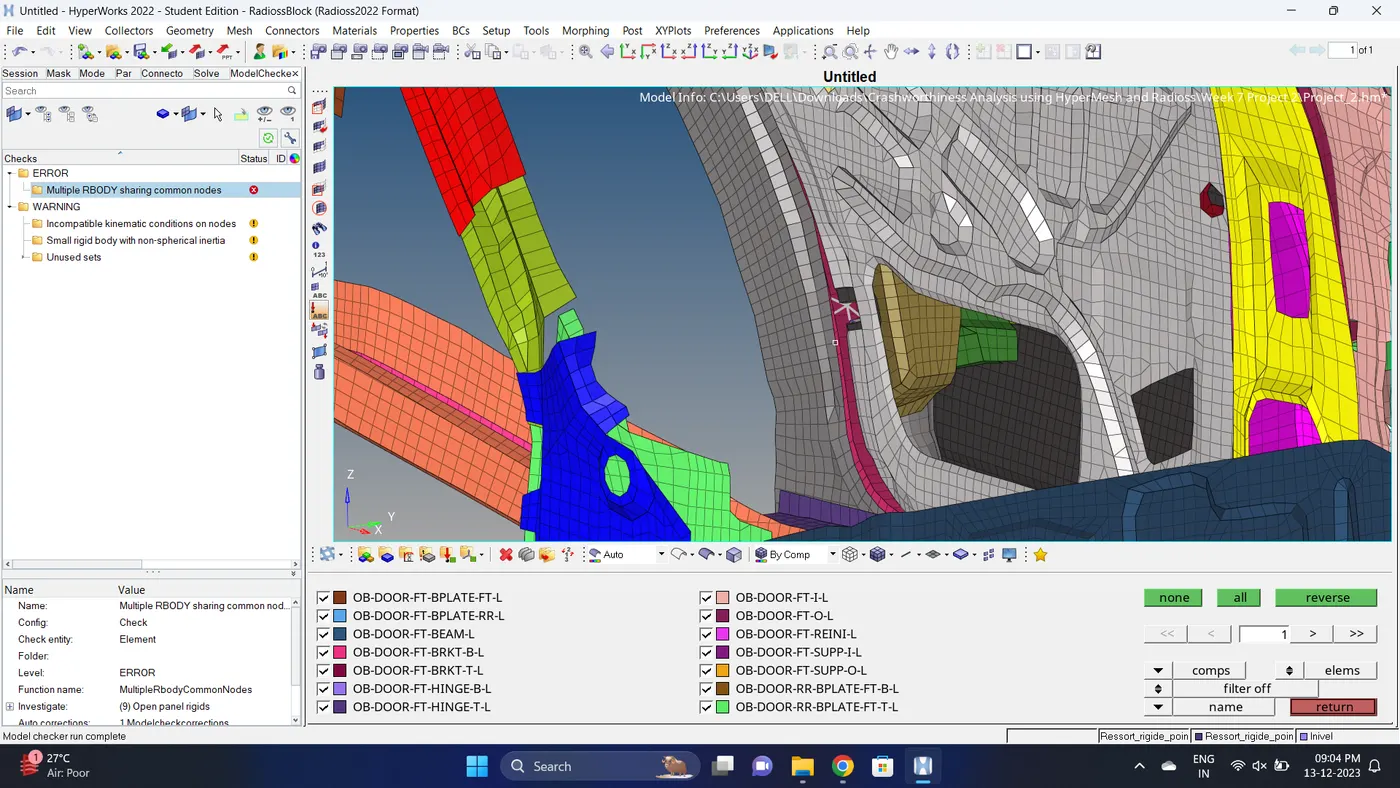
Note: For the Rigid body error it is seen that it location is door lock. Since it is small space it has less node for making connection. But it not cause any issue with the simulation.
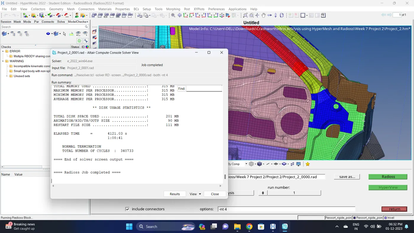
24. Run the simulation.
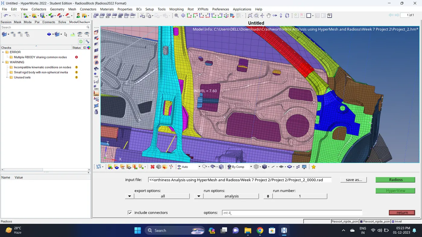
Go to Analysis - Radioss - click on save as, Rename the file to Project_2 and at the end type .rad - Ensure that export option is set to all and Include connectors is tick - Click Radioss to run the simulation.
Note: If the stimulation is not running it taking time then copy the given input 0000.rad and 0001.rad file to folder, Rename both the file to Project_2, click on the 0000.rad file click save and overwrite it.
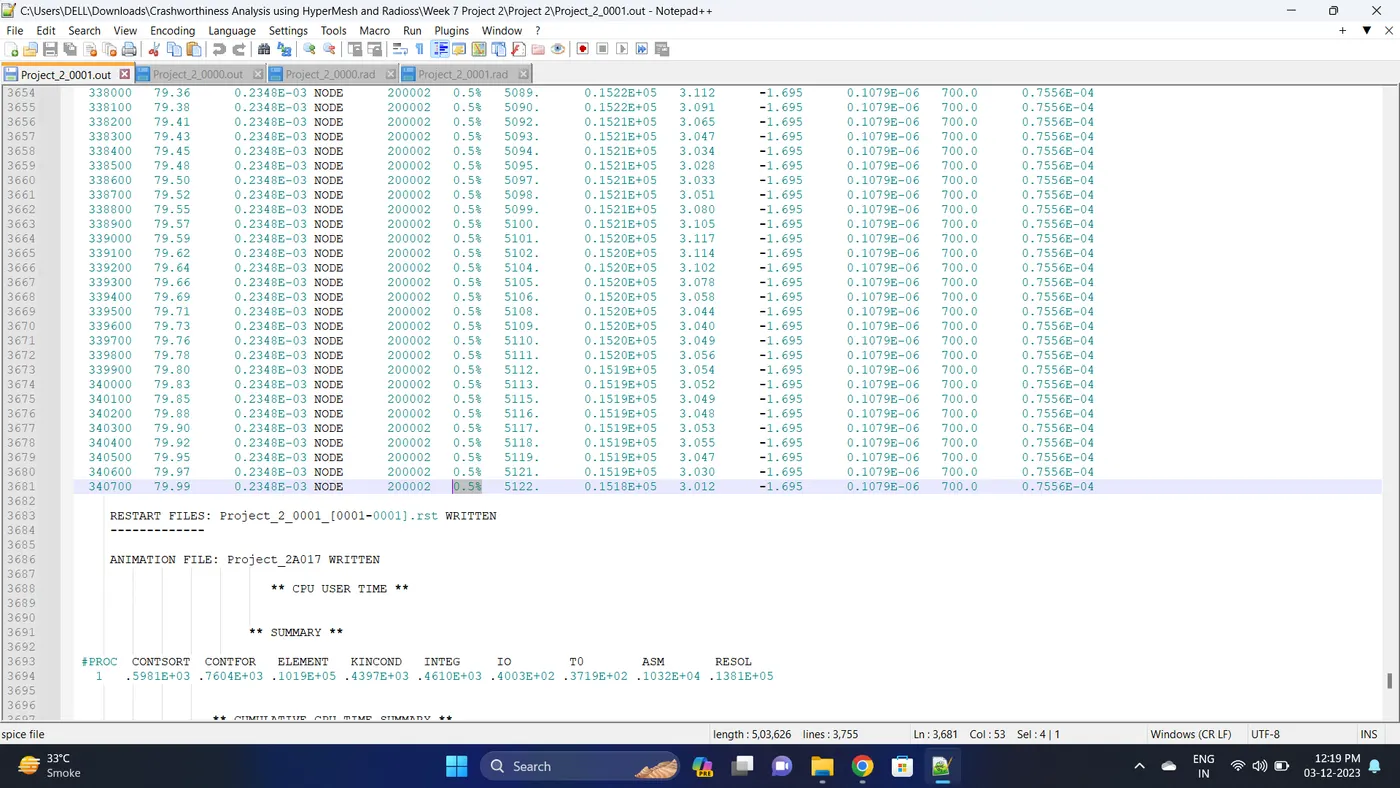
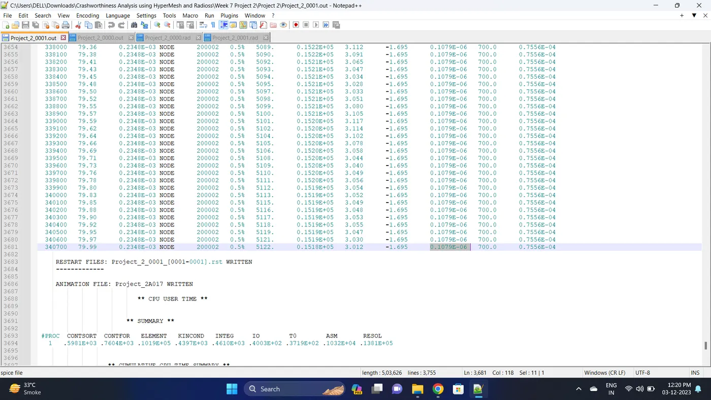
25. Open 0001.out file in notepad ++ and check the maximum total energy error and mass error.
The torelance for the energy error is -15 to +5 % and mass error is upto 2 %.
Energy error is 0.5%.
Mass error is 0.1079E-06.
26. Open the Hyperwork in Hypergraph 2D view.
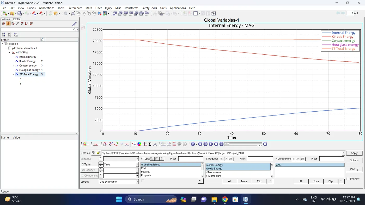
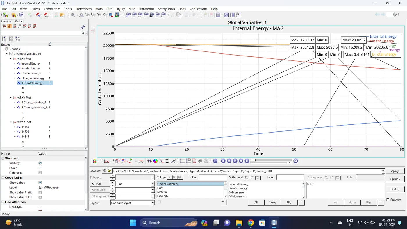
27. Open the T01 file and select the Global Variable - Internal energy, Kinetic energy, Contact Energy, Hourglass Energy and Total Energy - Click apply to plot the graph.
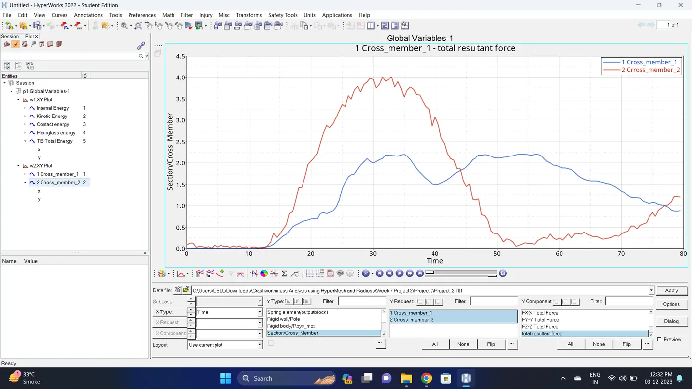
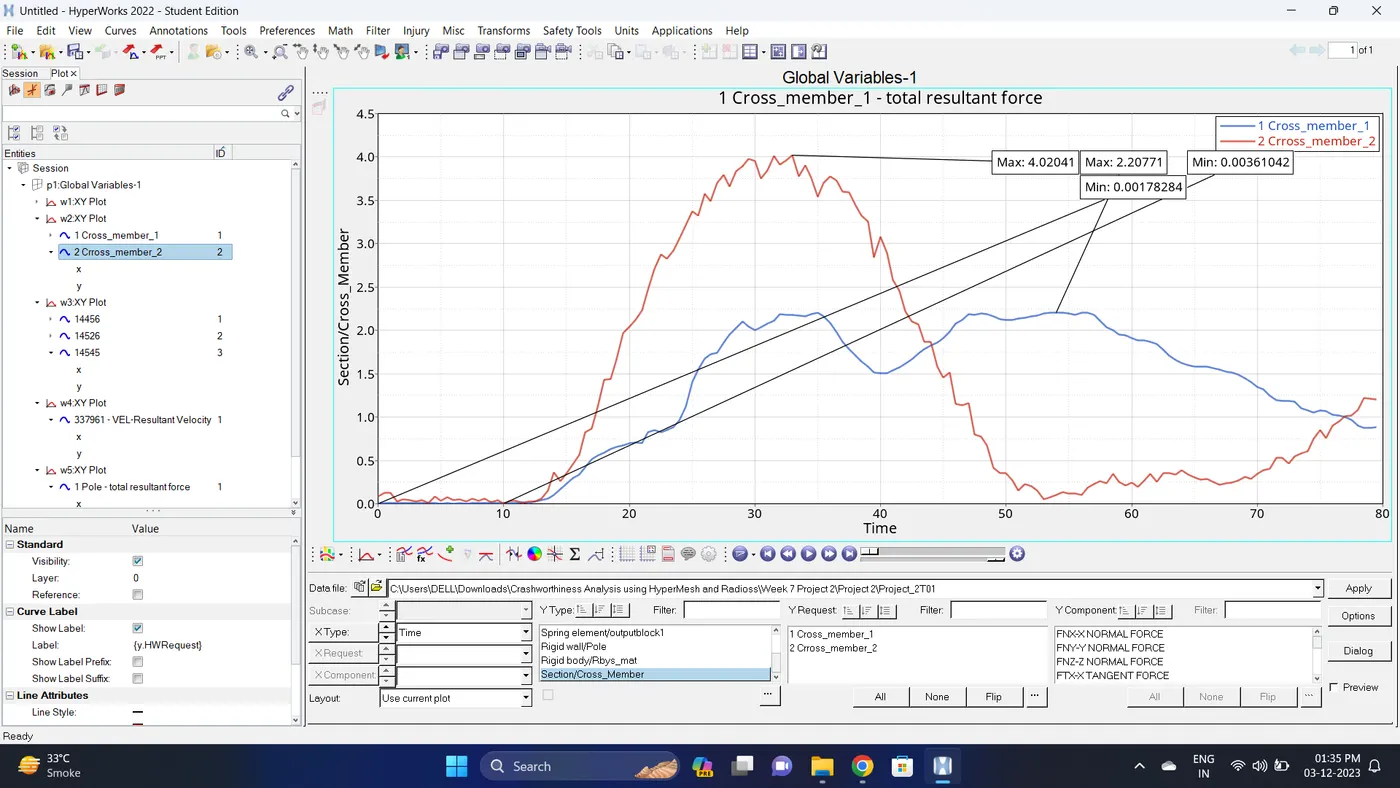
28. Change the windows page layout to 2 and in second window plot the Sectional forces.
To Plot the graph select Section/Cross_Member - Select all the sections - Total Resultant Force - Click Apply.
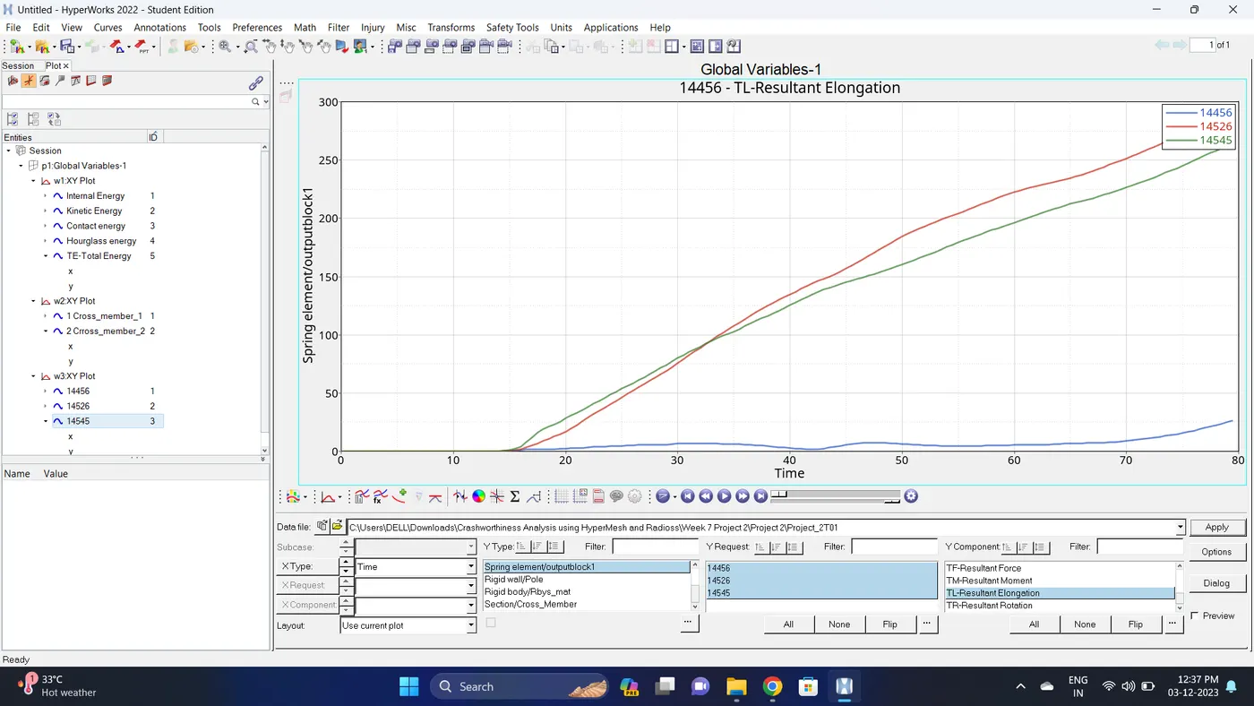
29. Change the windows page layout to 3 and in third window plot the Intrusion.
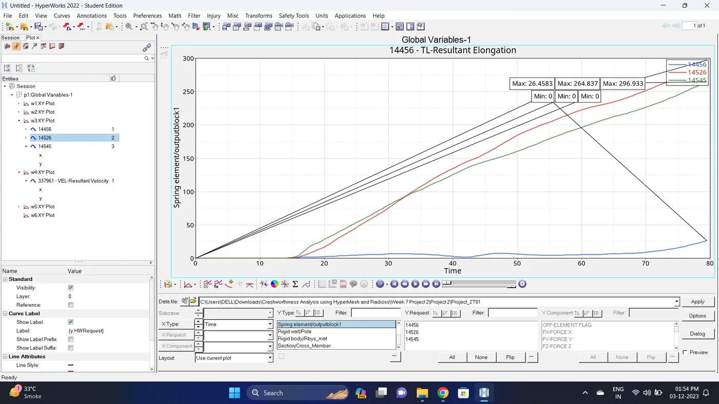
To plot the Intrusion select Spring element/outputblock1 - Select all the spring elements - Resultant Elongation - Click Apply
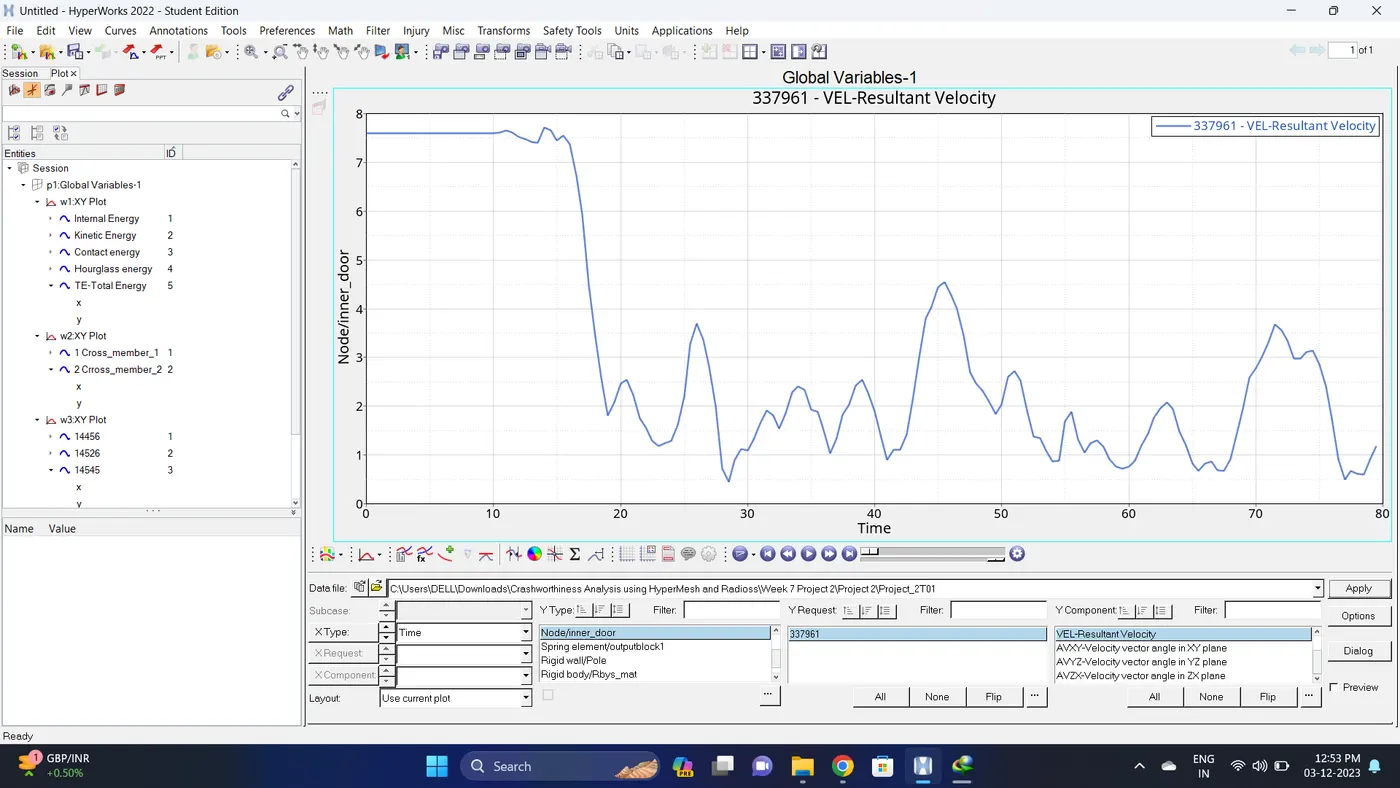
30. Change the windows page layout to 4 and in four window plot the Peak velocity of an inner node of the door.
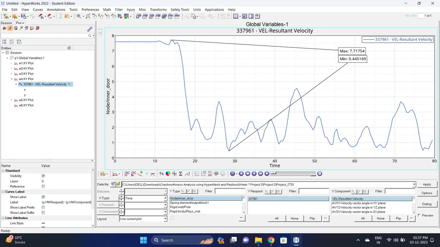
To plot select Node/inner_door - select node id - Resultant Velocity - Click Apply.
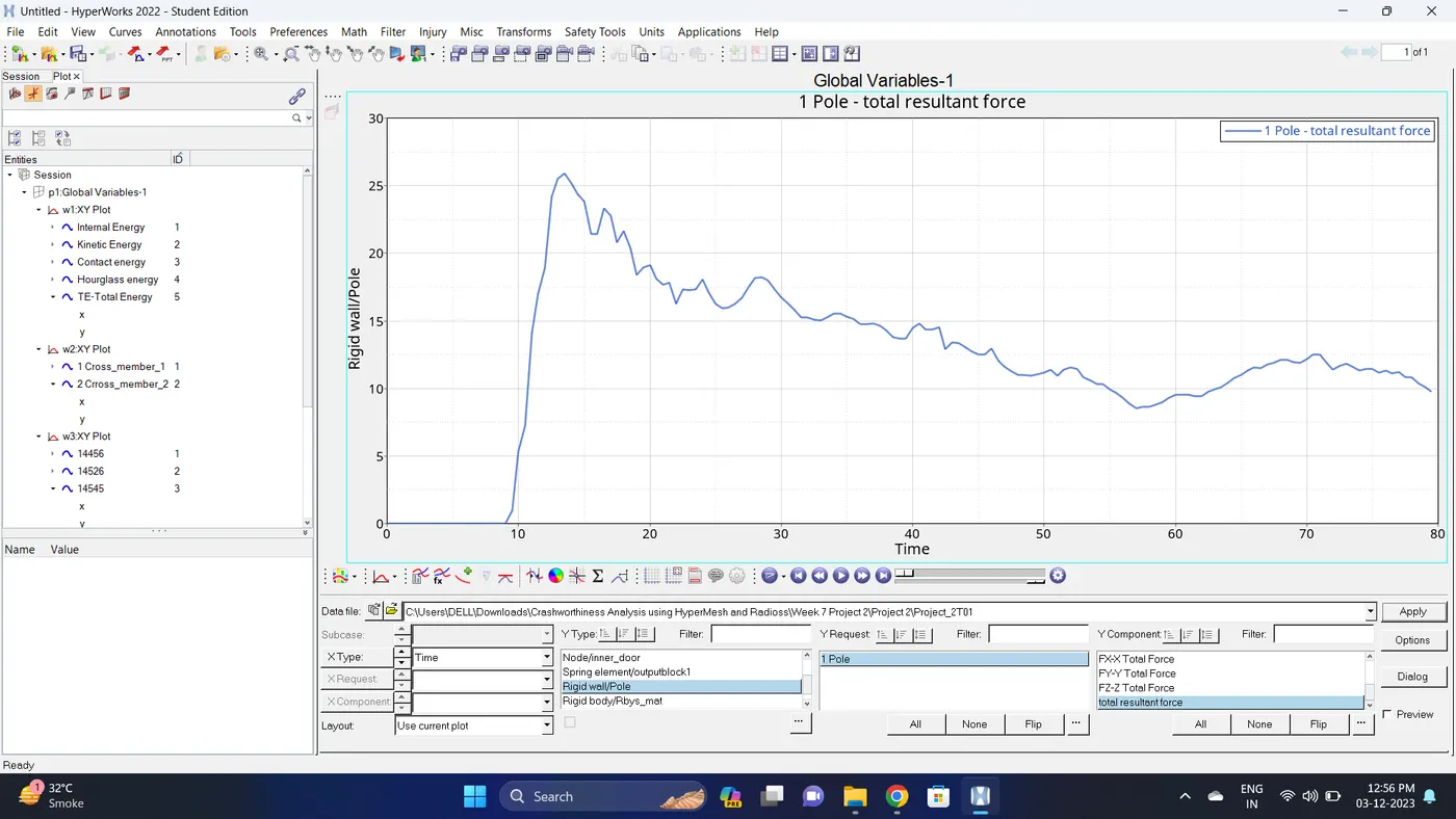
31.Change the windows page layout to 6 and in fifth window plot the rigid pole forces graph.
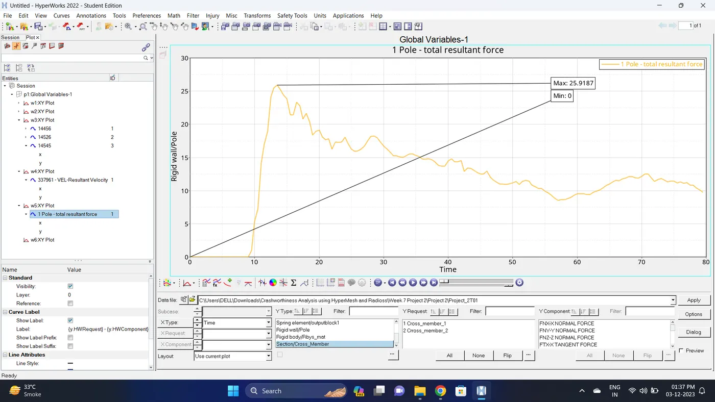
To plot graph select Rigid wall//Pole - 1 Pole - total resultant force - click Apply
32. Note down the minimum and maximum value of various Energy by right click on any energy - Single curve math - Min Note. similarly do for maximum
Note: after getting graph reading turn off that graph and do next reading.
| Sr. no | Name | Minimum | Maximum |
| 1 | Internal energy. | 0 KN.mm | 5096.6 KN.mm |
| 2 | Kinetic energy. | 15209.2 KN.mm | 20212.8 KN.mm |
| 3 | Contact Energy. | 0 KN.mm | 0.416161 KN.mm |
| 4 | Hourglass Energy. | 0 KN.mm | 12.1132 KN.mm |
| 5 | Total Energy. | 20205.6 KN.mm | 20305.7 KN.mm |
| 6 | Sectional Forces on Cross member 1 (Total Resultant Force). | 0.00178284 KN | 2.20771 KN |
| 7 | Sectional Forces on Cross member 2 (Total Resultant Force). | 0.00361042 KN | 4.02041 KN |
| 8 | Rigid Pole Forces (Total Resultant Force). | 0 KN | 25.9187 KN |
| 9 | Intrusion at B pillar 14545 (Resultant Elongation). | 0 mm | 264.837 mm |
| 10 | Intrusion at Hinge Pillar 14456 (Resultant Elongation). | 0 mm | 26.4583 mm |
| 11 | Intrusion at Fuel tank region 14526 (Resultant Elongation). | 0 mm | 296.933 mm |
| 12 | Peak velocity of an inner node of the door. | 0.445169 m/s | 7.71754 m/s |
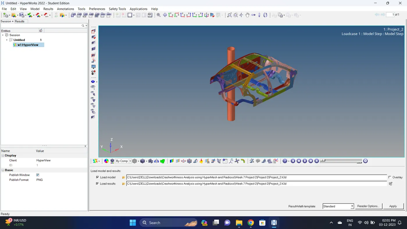
33. Open the Hyperwork in Hyperview view.
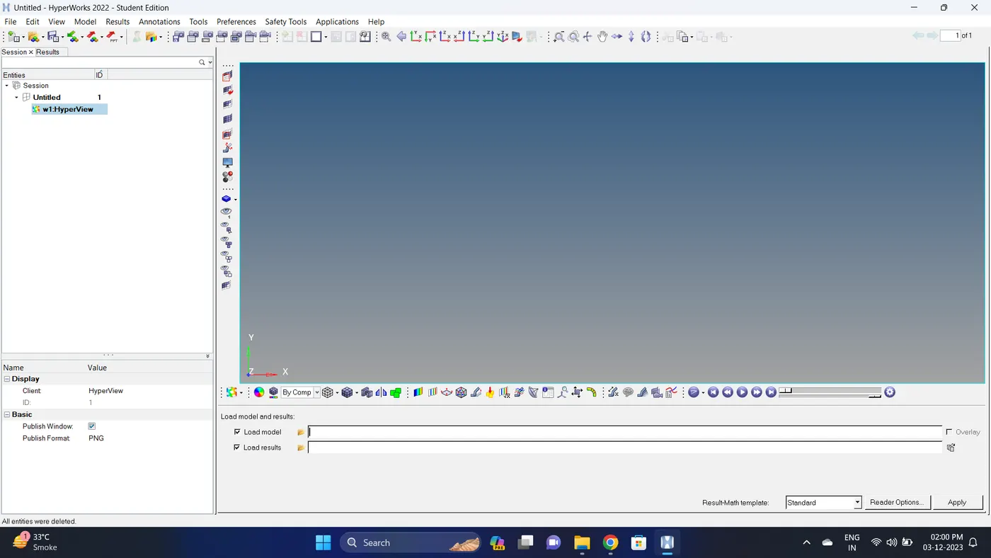
34. Import the .h3d file.
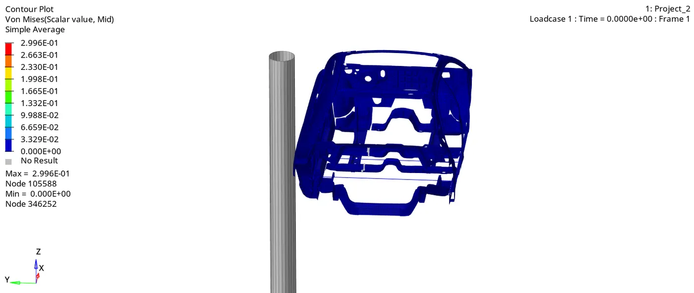
35. Go to the contour - change result type to Von mises (s), averaging method to simple, click on apply and play the animation.
Maximum stress = 0.2996 and Minimum stess is 0.
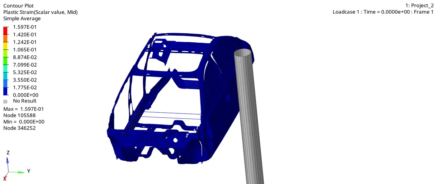
36. Go to the contour - change result type to Plastic Strain (s), averaging method to simple, click on apply and play the animation.
Maximum strain = 0.1597 and Minimum stain is 0.
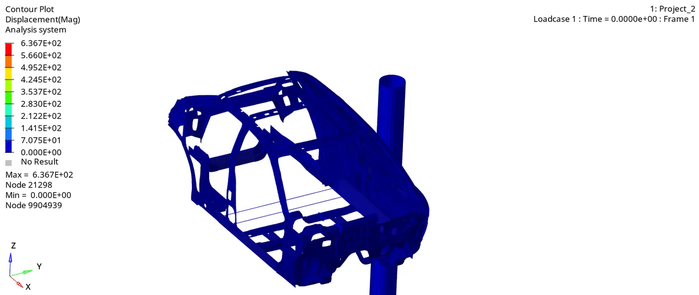
37. Go to the contour - change result type to Displacement (v), averaging method to simple, click on apply and play the animation.
Maximum Displacement = 636.7 and Minimum Displacement is 0.
Report:
The side rockers are the main energy-absorbing structure in case of a side impact, they very often include inserts that are specifically designed to improve the energy-absorption capability. These inserts are generally multi-cell-extruded bars made of aluminum or reinforced plastic materials, but sometimes, rockers have internal diaphragms made of stamped steel sheets or internal diaphragms combined to constitute multi-cell-reinforcing solutions. Usually, the pack has a perimetral frame, which gives stiffness to the pack but is also intended to contribute to the crash energy-absorption performance as an addition to the side rocker’s structural capability.
1. We saw in the animation that the most deformation took place in the middle pillar area and the stress is then passed to the side of the rest of the components.
2. We observed that the impact of the crash is mostly at the middle pillar side door of the car and by looking at this we can say that the seating area of the driver and passenger will be also impacted which can cause severe injury to them.
3. It is seen in the middle cross member deformation is more compare to side cross member due to this it is seen that force is cross member 1(Middle) is 2.20771 KN and in cross member 2(Side) is 4.02041 KN.
4. Intrusion at B pillar (264.837 mm) and Fuel tank (296.933 mm) is high due to this there is chances of injury to the front Passenger and damage to the fuel tank this may cause the fire accident. At Hinge pillar (26.4583 mm) there are small Intrusion due to this there small injury may occur to the rear Passenger.
5. Peak velocity of an inner node of the door is 7.71754 m/s from this we can say that when the impact happens door inner panel moves at the velocity upto 7.71754 m/s. if there is a person sitting there. There will a impact force will be experienced by Passenger.
Recomendation for Reducing Fuel tank Intrusions:
1. Side crashes account for the second highest frequency of death and serious injuries compared to frontal impact, there is very little space inside the vehicle interior in which to absorb energy and severe injuries to the Head and Chest are common.
2. During side Impact, the door comes first in contact with the hitting vehicle and pole. As the space available between the occupant inside the vehicle is limitted and there is no space for energy absorption as compared to front end collision, Therfore Design of Side impact beam inside the door should be such that it sustain high load or transfer high load or forces with smaller displacement. An anti-intrusion bar or beam is a saftey device, installed in most of cars and other ground vehicles, which must protect the passenger from side impacts.
3. The location of Impact is very close to Passenger, and there might be chances of high fatal injuries to the occupant that is sit inside the car.
4. In side impact collision some time the impacting vehicle may be large trailers , Pole (consider as rigid), so at that situation there is high chances of injuries because of large deformation or intrusion in the car.
5. The role of Anti-intrusion bar is to absorb kinetic energy of the colliding vehicle and convert partially into internal work of the members involved in crash, Therefore increasing the side door strength by adding more anti-intrusion bar, we can reduce the overall amount of intrusion.
6. But as we see in the simulation our Cross-members and roof rail is going to bend / Buckled during the crash, due to this the overall structure of passenger cabin is deformed a lot, so we have to increase the stength of the both roof rails and cross-members so that it transfer all the forces to other members without much having large deformation, by this we can overall protect or we can overall reduce the intrusion and deformation of Passenger or Occupant cabin.
7. To reduce the Fuel Tank intrusion we can add one more cross-member nearer to fuel tank, or either we can design a cross-member in such a way that it can't buckle during side crash and maintain the stability during crash.
8. Also to reduce the chances of injuries, vehicle needs to equiped with Center airbags and Side airbags to reduces the impact and protects the Occupant Heads during crash.
Conclusion:
The given model was simulated for the side crash using Radioss and the results obtained were validated. The graphical results were plotted for all the test cases. From the simulation, it can be observed that there was maximum deformation in the cabin, and also maximum intrusion was found in the cabin area. This is due to the limited number of nodes in the student version some of the BIW, engine blocks, suspension system, etc are removed, so the results are not as in real condition. After understanding these we will get to know what all things we should do on this car to make it safer. For example to decrease the amount of intrusion in the Fuel tank region we can introduce a inserts (Anti intrusion bar) there and also for the B-Pillar for the passenger safety.
Note: Due to file size. The file are been uploaded on the Google drive and link is provided in the attached notepad.