Assignment 7-Side Pole Crash Simulation Challenge
Aim :
- To be able to case set up for side pole crash test.
- Set up the case as per given conditions in the questions.
- Able to request output requests as per case.
- Able to plot curves and analyze differences if any.
Procedure :
1 ) Import model:
- Go to import from menubar.
- Import "neon_side_reduced_0000.rad file.
2 ) Check unit system of model:
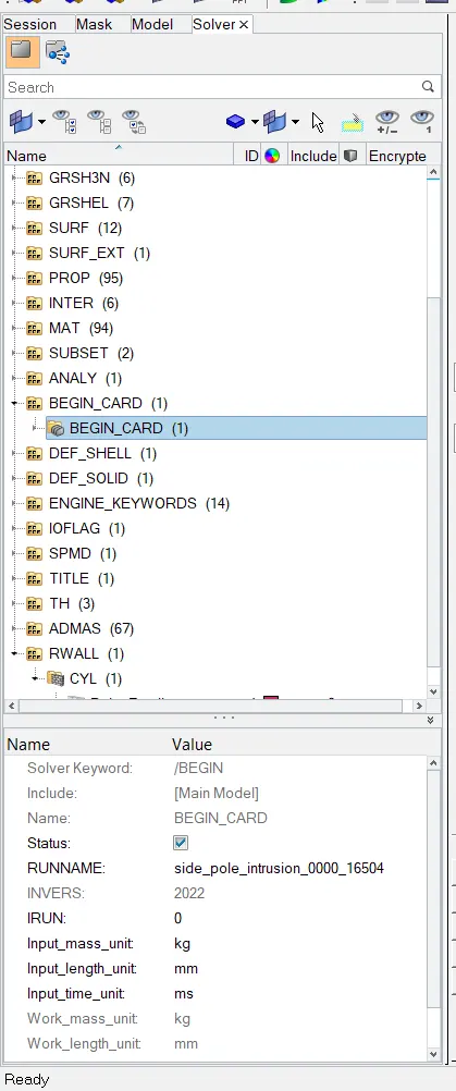
- Go to solver browser.
- Go to "Begine card".
- Confirm the unit system of given model is same as given in question.
3 ) Create Interface :
- To create interface go to solver browser.
- Right click on white area.
- Click create.
- Select inter.
- Select type of interface.
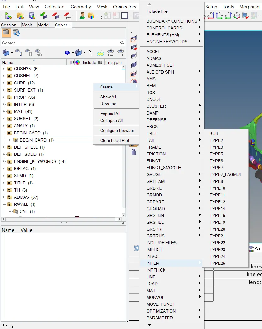
- Create type_7 interface. This will create a contact between node and surface of elements. Nodes are slaves and surface are master elements.
- Fill appropriate details in the type_7 contact interface card.
- Give friction as 0.2.
4 ) Create a Rigid Pole :
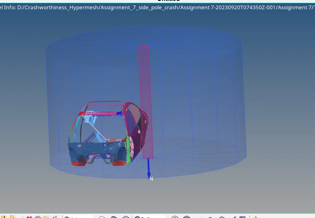
- Rigid Pole is a type of cylindrical rigid wall.
- Create a rigid wall near B pillar section.
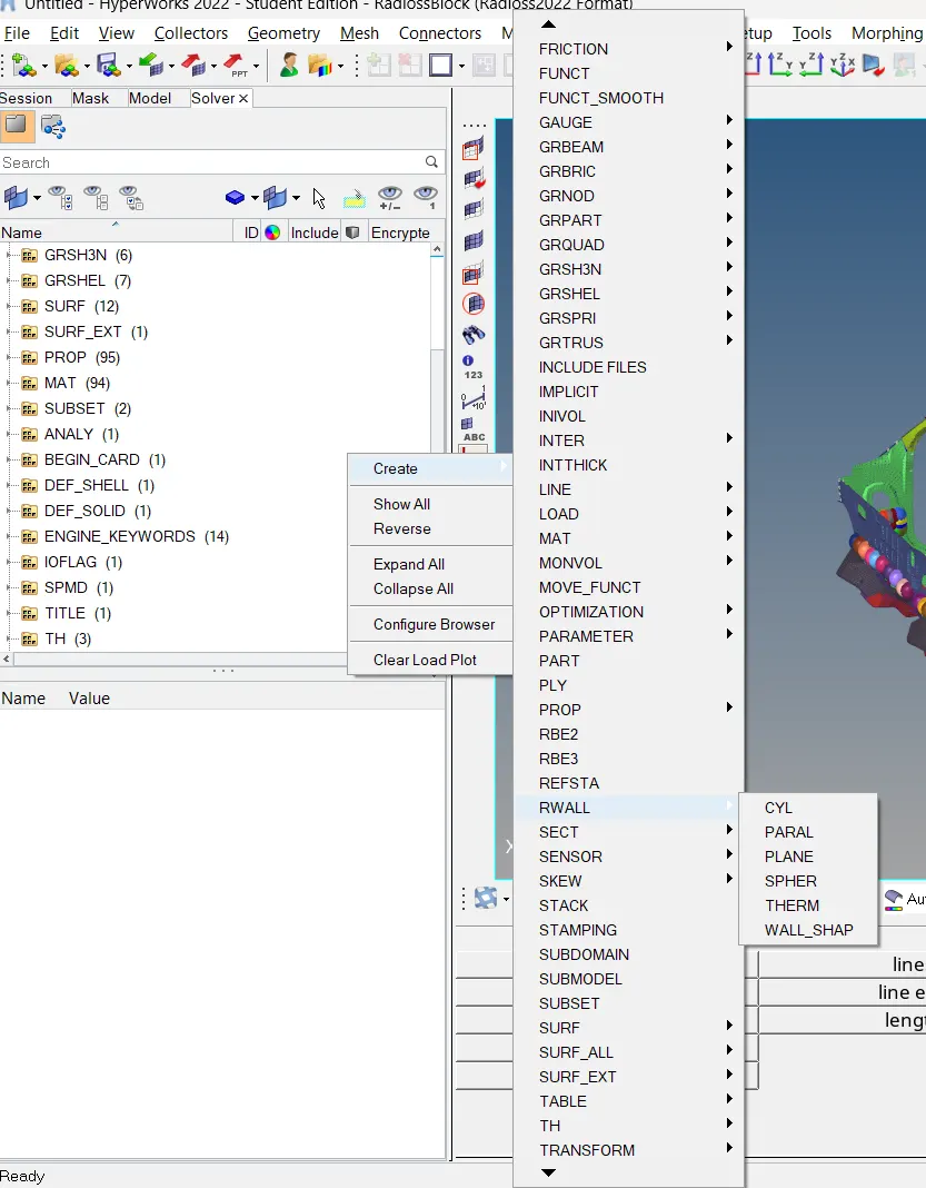
- To create rigid wall go to > solver browser.
- Right mouse click on white section of solver browser.
- Click on create.
- Select RWALL.
- Select cylindrical.
- Give Co-ordinates, normal direction.
- Select "slide" type as "sliding with friction" and give friction value as 0.1.
- Provide search distance and diameter.
- Diameter of the pole should be 254 mm as per FMVSS - 214 STANDARDS.
5 ) Give initial velocity :
- As per FMVSS-214 standards, speed for side pole crash test is 32 km/h ( 20 mph ).
- To assign velocity to car model go to solver browser.
- Right click on white surface of solver browser.
- Click on create.
- Click on "Boundary Conditions"
- Click on INIVEL.
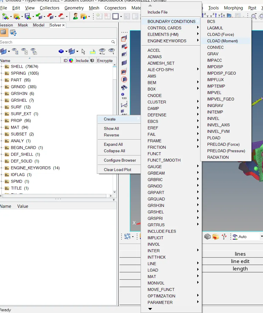
- Enter all the required values.
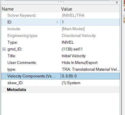
- Select type as INIVEL, which is a keyword of initial velocity.
- Create a node group by selecting all the nodes.
- Give type of velocity as TRA. (Translational Material Velocity)
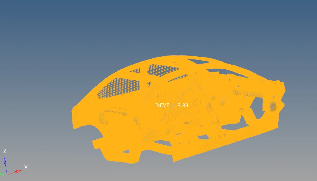
- Give velocity component as 8.89 mm/ms in y-axis.
- Define a skew.
6 ) Create sections in cross members.
- Sections are created to measure the forces passing through them.
- To create section go to solver browser.
- Right click on white area of solver browser.
- Click on "create".
- Select section.
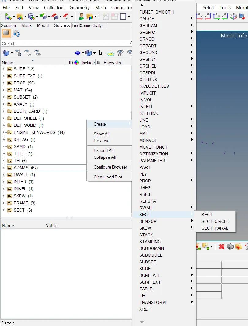
- Fill all the required parameters.
- Select geometry type as "Infinite Plane".
- Select "N1,N2 and N3" Nodes.
- Provide fram_Id.
- Give delta T and alpha values.
- Select "grshel_id" and "grtria_id".
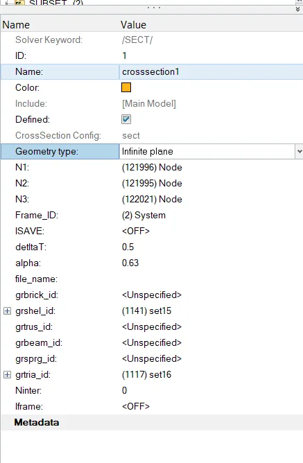
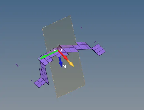
- Create such sections on both cross members and at required section.
7 ) Create springs to measure intrusions:
- Intrusions are the deformation of parts.
- So, it is very important to measure the deformation happened in the passanger compartment.
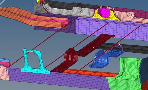
- There are no. of methods to measure intrusions, one of which is to create spring between two nodes and measure its displacement.
- To create spring go to 1D panel.
- Select rigids.
- Create spring.
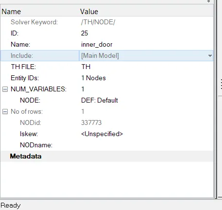
8 ) Create output request to measure peak velocity of inner node of door.
- In case of side pole crash test it becomes important to measure the velocities on the nodes.
- We can do that by requesting an output TH node. Where we can measure displacements of nodes.
- To create TH node request go to solver browser.
- Right mouse click > click on create.
- Click on TH > select node. ( Select node 337773 as given in question ).
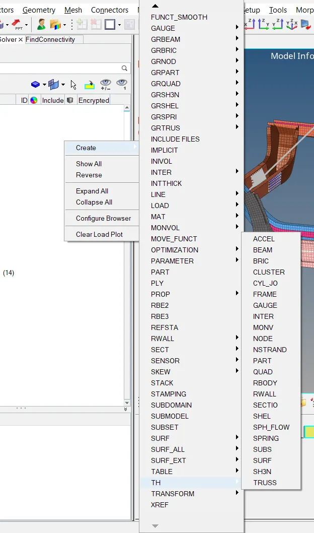
- Select TH FILE type as TH.
- In the Entity_IDs select the node whose displacement is to be measured.
- Select NUM_VARIABLES as 1.
9 ) Create output requests:
- To get the results we have to request the outputs i.e., TH files.
- To request TH output go to solver browser > right click on white area > click on create.
- Click on TH > Select output that we want to request.

- Select Accel, inter, node, rwall, sectio one by one to get desired result file.
10 ) Modify Engine files
- Change Tfreq to 0.1 from ANIM/DT option.
- In ANIM/ELEM tik the EPSP and VONM checkbox to get the results.
- Change time step to 0.0005 in DT/BRICK, DT/INTER, DT/NODA. They are the time step for Brick elements, Contact interfaces and nodal timesteps.
- Go to RUN file and change tstop to 80 ms.
- Perform all the above checks and modify accordingly for this case.
PERFORM CHECKS -
1 ) PENETRATION AND INTERSECTIONS
- To check penetration go to TOOLS from menubar > select PENETRATION CHECK.
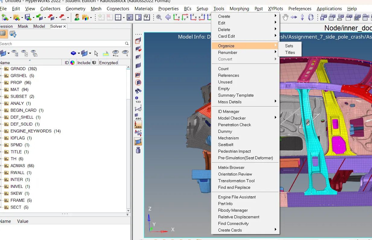
- Check Penetration browser will open in browser section.
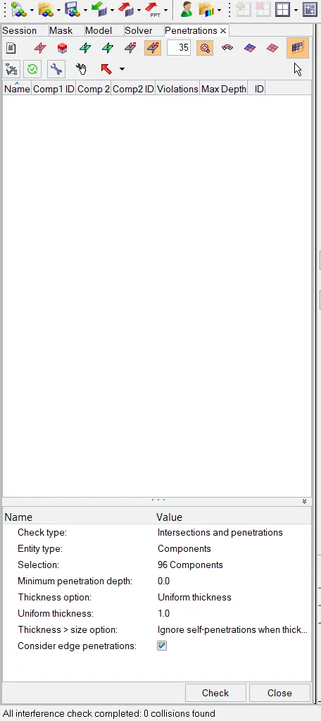
- Fill all the required parameters and click on check.
- If there are any penetration then they will be shown in the browser window.
- We have 0 penetrations and intersections in this model.
2 ) MODEL MASS AND COG
- To check mass and COG of model go to TOOLS > mass details.
- New window will open.
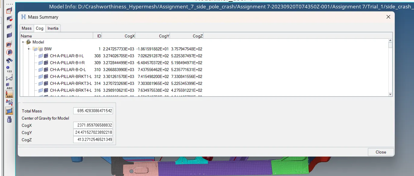
- Mass of total model and COG points can be checked from here.
- Mass of this model is 695 kgs.
3 ) MODEL CHECKER
- Go to TOOLS from menubar > Model Checker > Radioss Block.
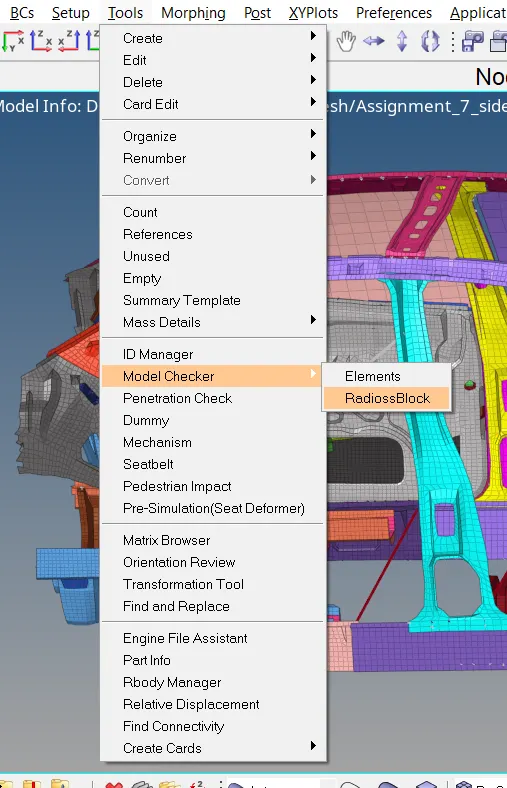
- New browser will open.
- Click on right mouse button in browser window > click on RUN.
- Full model will be checked.
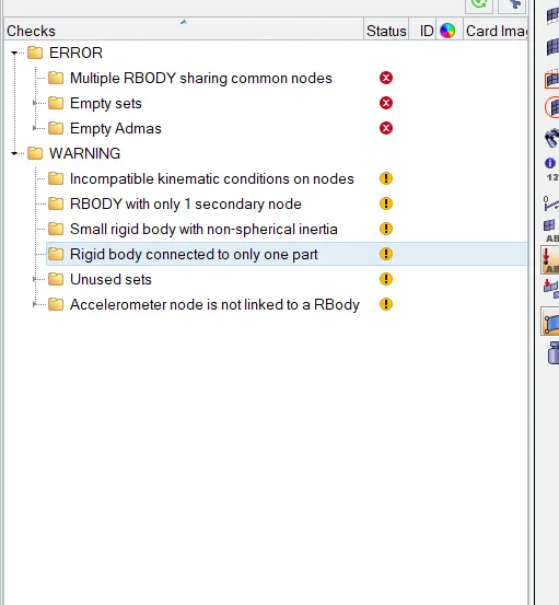
- If there are any error or warnings present in the model they will be displayed in window.
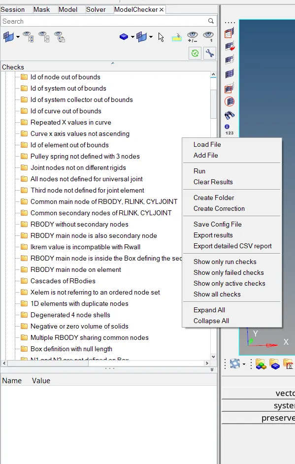
- Errors and warnings are shown in browser area after model checker run is completed.
- Remove all the errors from the model.
- To automatically remove the errors right click on the error and click on Fix error.
4 ) RUN SIMULATION
- Once all the checks are completed model is ready to perform simulation.
- To run the model go to > Analysis page > Click on Radioss.
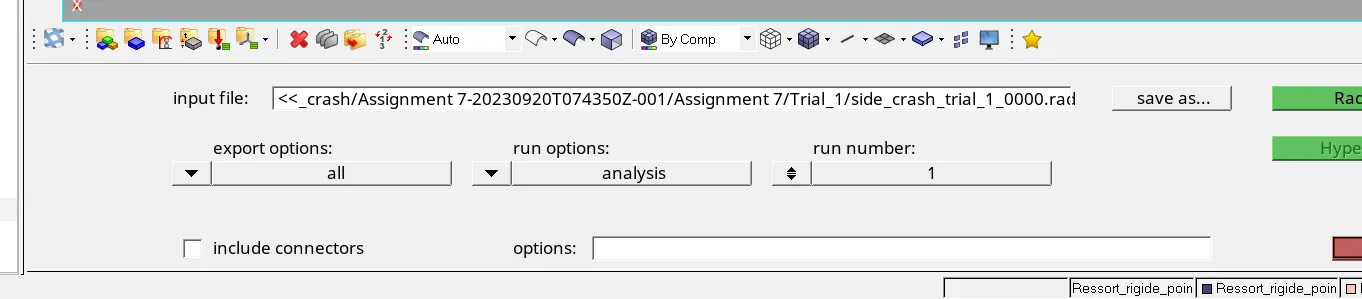
- New page will open.
- Insert "-nt 4" in front of options.
- Tick the checkbox of include connectors.
- Save the file > click on Radioss.

ANIMATION FILE AND RESULTS :
- To view the animation files open "Hyperview".
- To represent the results in graphical forms open "HyperGraph 2D".
- In hyperview, number of animation can be observed.Such as displacement, von mises stresses, Plastic strain and specific energies.
- Load the animation (.h3d) file and check the animation files.
- To check the results in graphical format switch window to HyperGraph 2D and load the T01 file.
ENERGY CURVES:
TOTAL ENERGY -
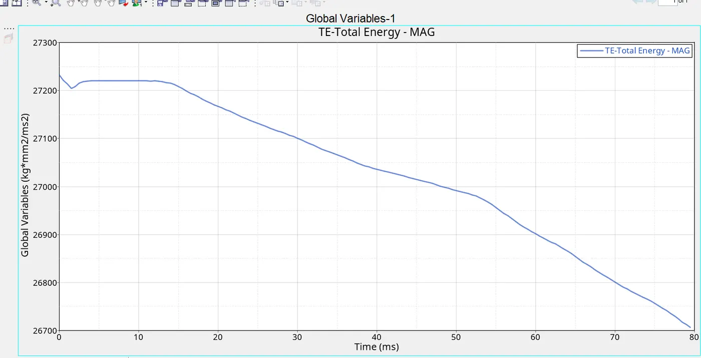
- This is the curve of Total energy. Total energy of the model is balance of kinetic, internal and contact energy.
- This is constant in initial period of model. This is the period when car did not struck the pole.
INTERNAL ENERGY -
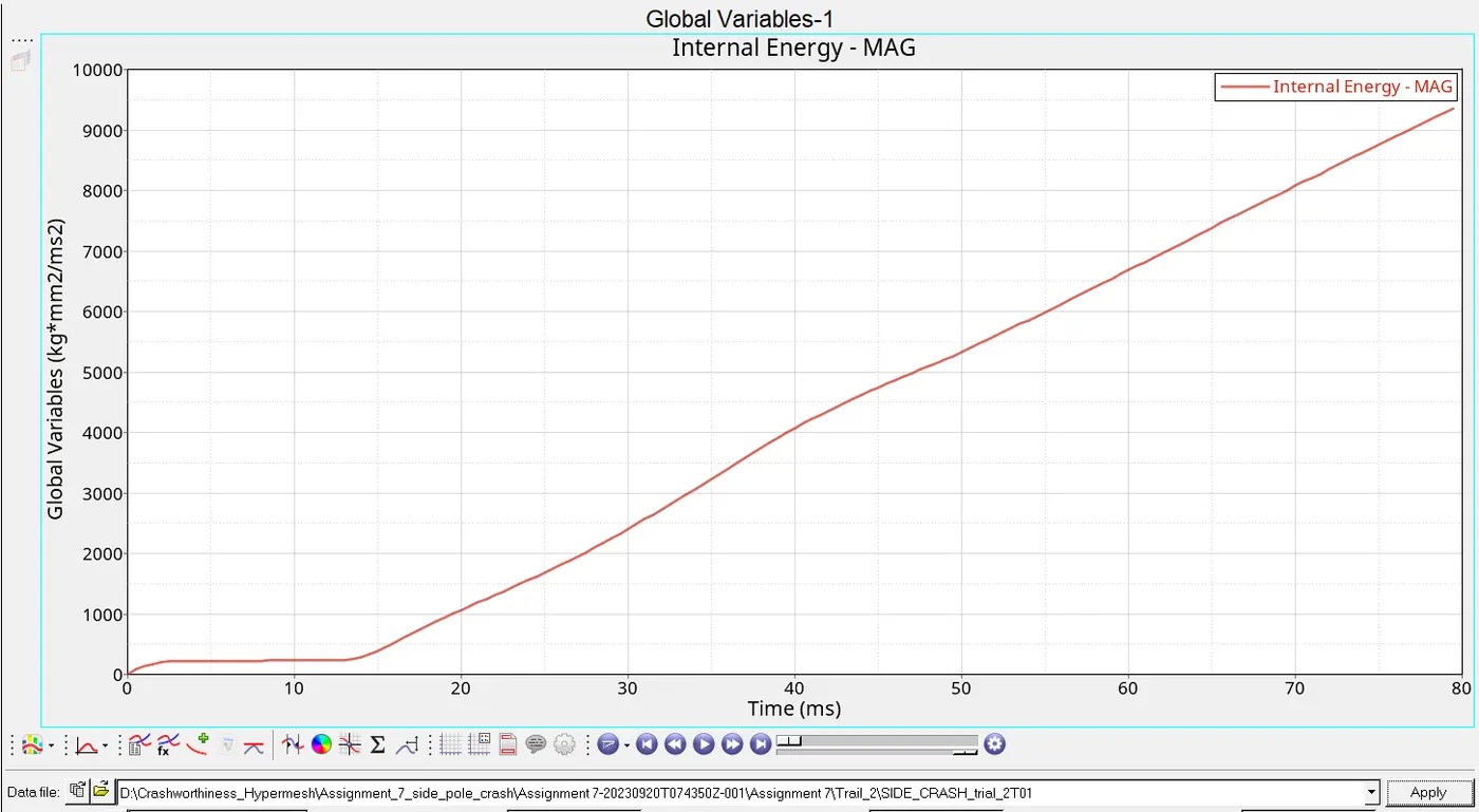
- This is the curve of internal energy.
- The value of internal energy in the initial 15 ms of curve is less because of the initial period in which the car was approaching the pole.
- Once it comes in contact with pole internal energy of car increases linearly due to the deformation of elements.
- The value of max. internal energy is 9364.35 kg*mm^2/ms^2.
KINETIC ENERGY -
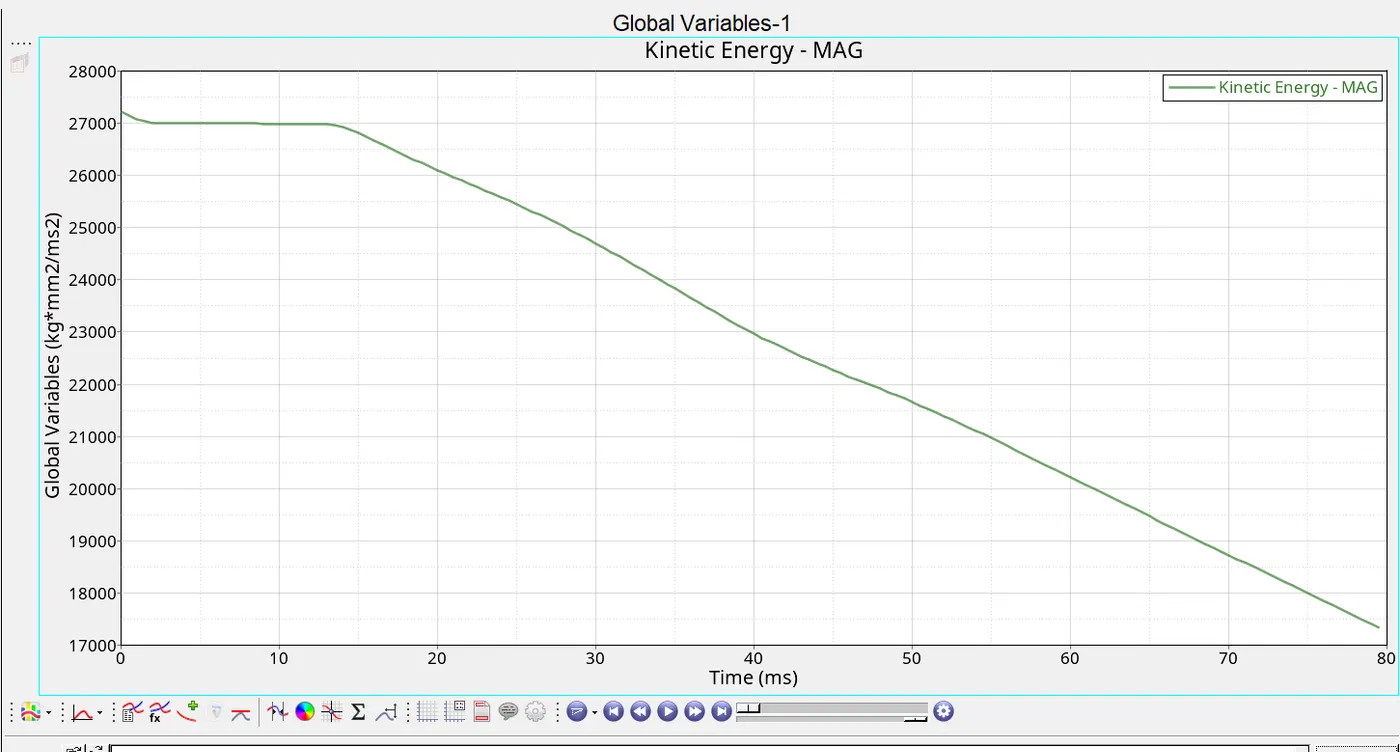
- Above curve is of kinetic energy.
- The curve is constant in initial period and then decreases as the car comes in contact with pole and its kinetic energy decreases linearly.
- The maximum value of kinetic energy is 27232 kg*mm^2/ms^2.
CONTACT ENERGY -
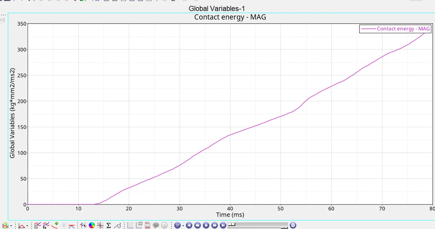
- This is the energy spend due to contact between elements.
- This curve is too constant till the car approaches pole and then it increases.
- Max. contact energy is 339.55 kg*mm^2/ms^2.
RIGID WALL FORCES -
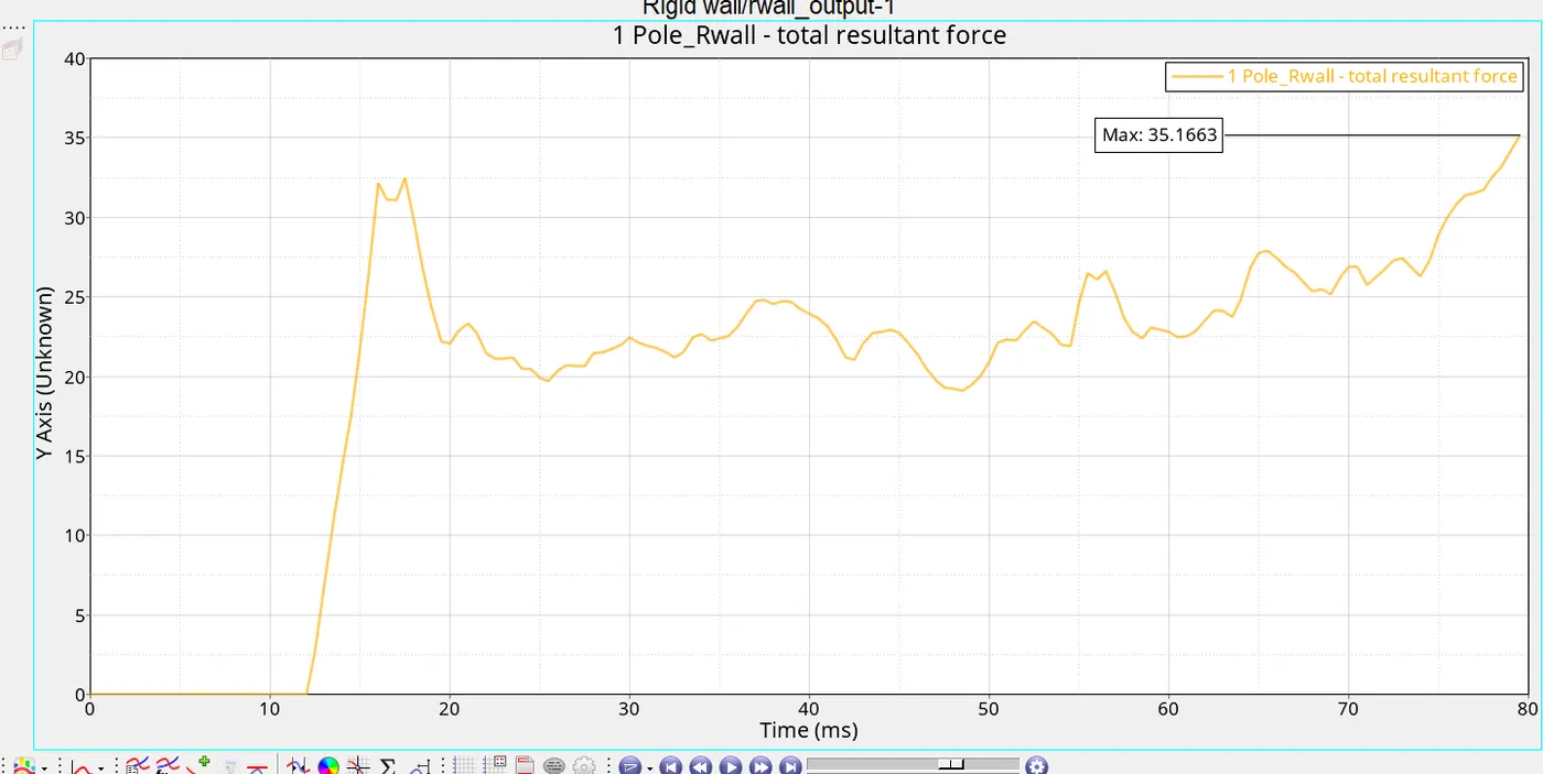
- RWALL forces are produced because of the reaction of wall on car.
- Car is crushing into pole/wall at higher speeds and due to its kinetic energy they exert forces on wall. But, wall is rigid and it can not absorb any forces thus it revert back all the forces back to the car.
- From the curve we see that there is no movement in intial phase of graph. That is due to inital gap between car and pole.
- Max. RWALL force is 35.16 kg*mm/ms^2.
SECTIONAL FORCES -
- Sectional forces are the forces which are calculated to measure the force passing through section of car.
- We created sections at 5 places.
- Max. sectional forces are observed in seat reinf. section - 3.953 kg*mm^2/ms^2.
- And the least sectional forces are observed in rear roobow section.
INTRUSIONS -
- We have created springs to measure intrustions at 3 sections.
- One at Bottom of B pillar section, second at hinge pillar and 3rd at fuel tank.
- Respective graphs are attached below.
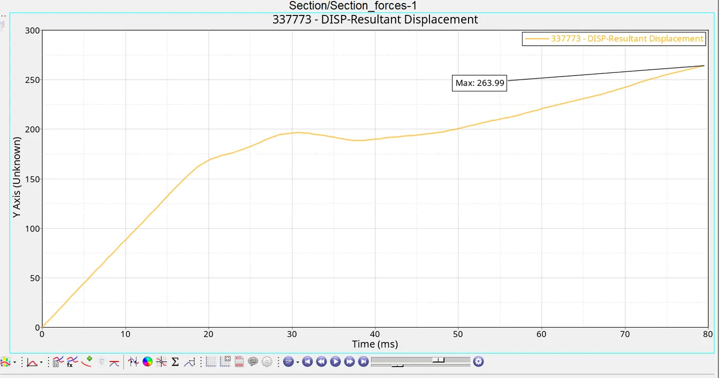
- The displacement of inner door node is 263.99mm.
- The displacement of inner node is linear for about 20 ms after that door nodes start to deform due to impact.
* Due to the size limit to upload file here by providing google drive link of .h3d file.
https://drive.google.com/file/d/1M7x75q9dqEt1b65bknhCRZHs565uMvYK/view?usp=drive_link .