Assignment 7-Side Pole Crash Simulation Challenge
AIM:
To perform Side Crash simulation for the given BIW structure using Radioss and HyperCrash.
CAR MODEL:
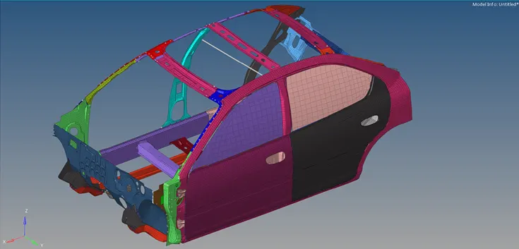
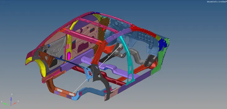
PROCEDURE:
- Import the starter file into the Radioss profile.
-
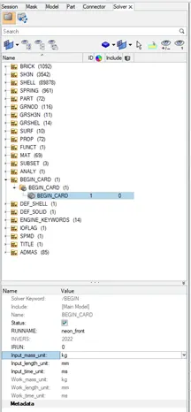
Check unit system in the BEGIN_CARD in the Solver tab. With reference to this unit system all input values are given throughout the procedure.
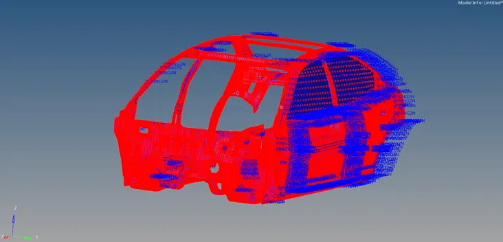
- Create Type7 interface along with recommended parameters (friction=0.2) and select the components in the model.
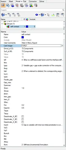
- Review and check the Interface contacts.
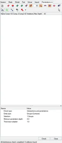
- Select penetration check option from the Tools menubar.
- Ensure zero penetration error for the model.
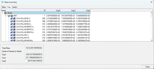
- Select and open the Mass details option from Tools menubar.
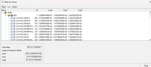
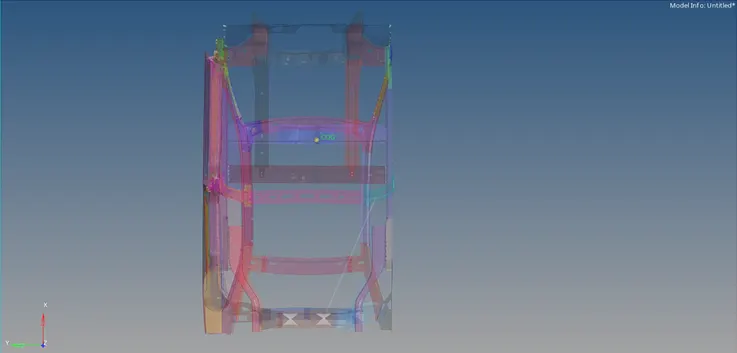
- Check the mass, which is 165 kg and the COG which can be viewed by creating node at the given coordinates.
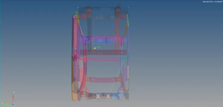
- The required value of total mass is supposed to be 700kg and the recommonded position of the COG is more towards the cross frame near to the driver seat.
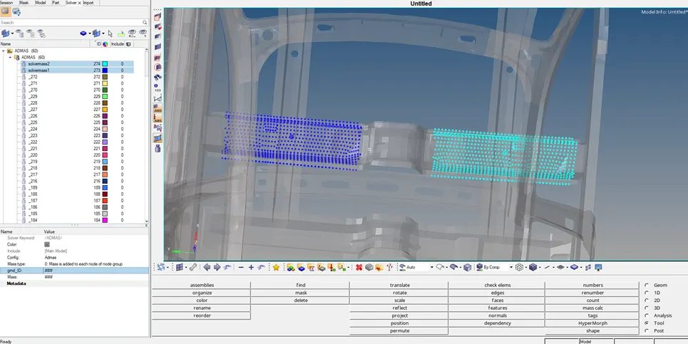
- Create or add extra mass to nodes using ADMAS card. The mass addition is to be adjusted more towards the middle frame (right side) region to obtain proper COG.
- Check the total mass and COG.
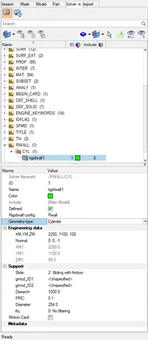
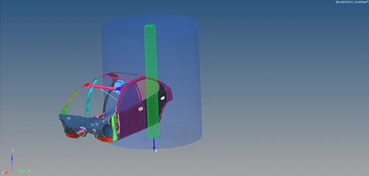
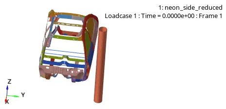
- Create a Rigid wall (cylinder) with friction=0.1, radius=254 and define XM,YM,ZM (wall plane coordinate) and Normal direction.
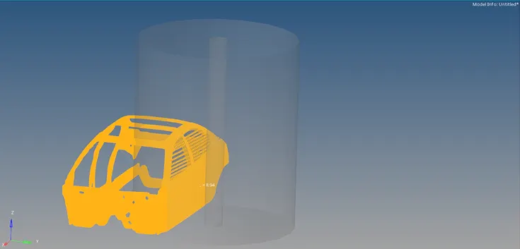
- Set a secondary search distance of 1000 that highlights the nodes(yellow)
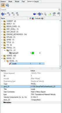
- Create and apply an Initial velocity of 20mph(8.94mm/ms) for all nodes.
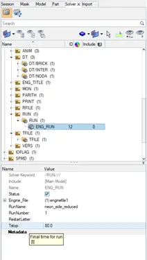
- Check and set the runtime to 80ms and time step to 0.5ms
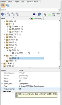
- Export the model as rad file from Hypermesh.
- Open new HyperCrash window (kN mm ms kg) and import the rad file.
- Run the Model checker available in the Quality menubar and check for errors.
- Warnings are reviewed for any critical effects and ignored if posssible.
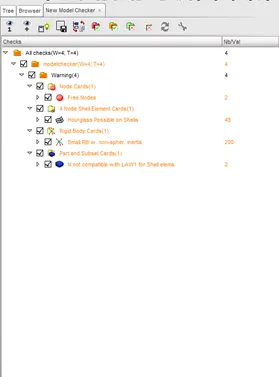
- Export the model rad file from HyperCrash and import and open the model into Radioss profile.
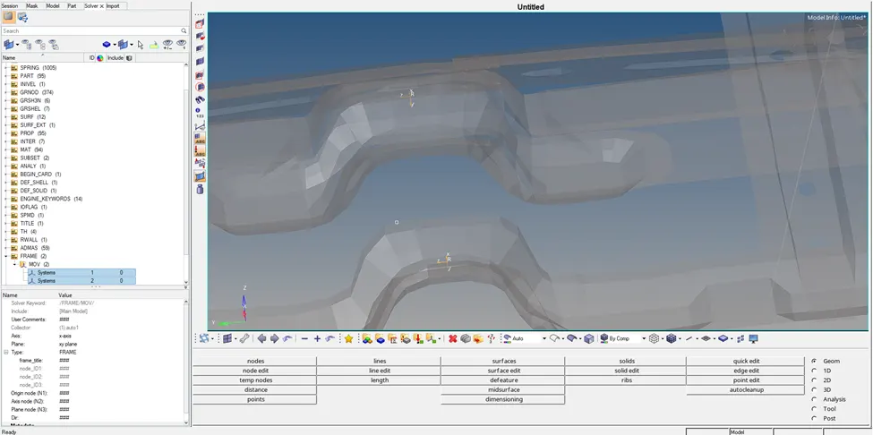
- Create Moving frames for the Cross-sections where the force variation has to be obtained.
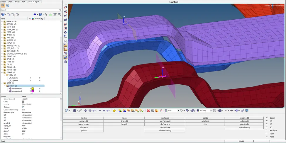
- Create the section(plane) w.r.t Moving frames and select the elements.
- Create TH card and assign the cross-sections for plotting the section output.
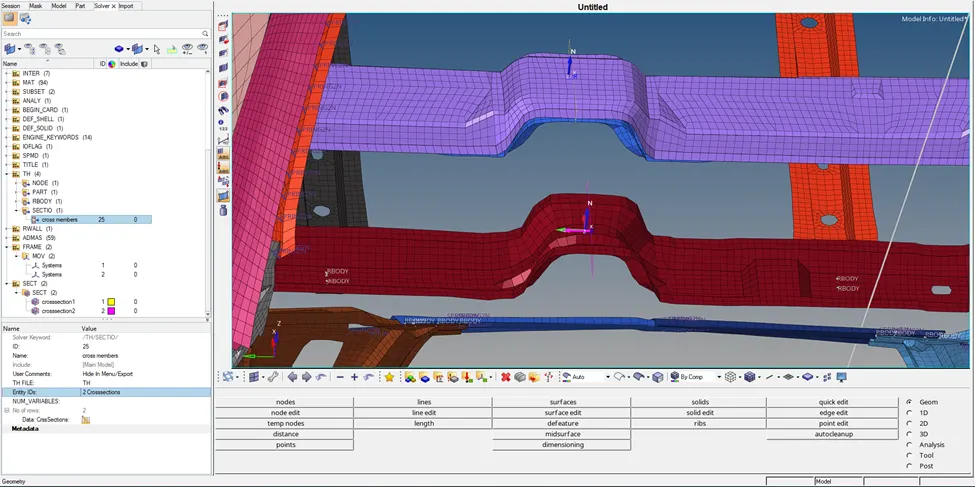
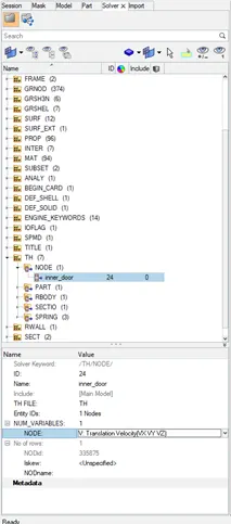
- Create TH card and assign the node(inner door) for plotting the velocity output.
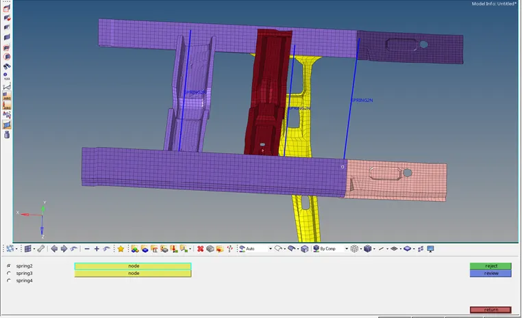
- Create spring elements connecting nodes from one side to opposite side nodes near Hinge pillar, B-pillar and Fuel tank.
- Assign spring property card for the above elements with lower stiffness value.
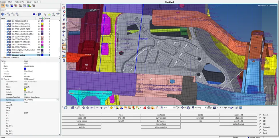
- Low stiffness springs can be used to determine the intrusions during the crash.
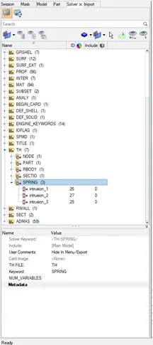
- Create TH card for spring to obtain enlongation output.
RESULT:
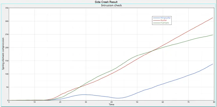
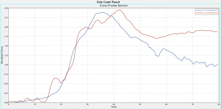
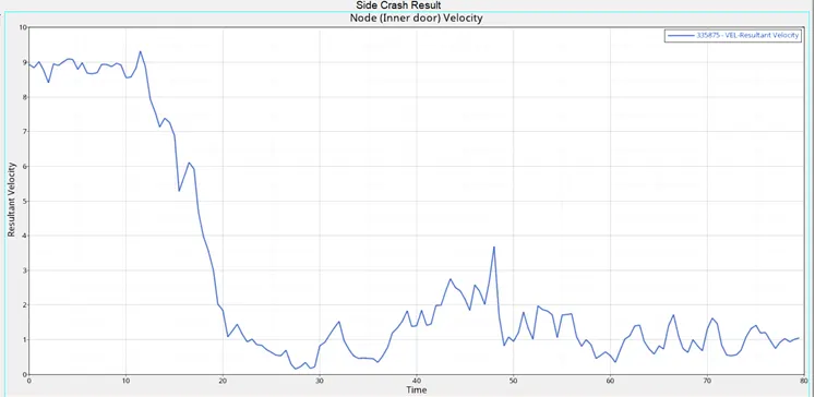
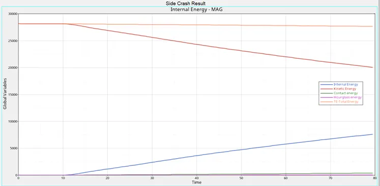
- A significant velocity drop is observed in the inner door node, reduces the impact on the driver side.
- Fuel tank region undergoes a displacement upto 250mm which is not ideal. Reinforcing the region to avoid punturing is necessary.
- Each frame carries an impact force close to 2.5kN during the crash.