Assignment 7-Side Pole Crash Simulation Challenge
AIM;To perform a side pole crash of a neon car biw assembly model.
INTRODUCTION;
SIDE POLE CRASH;
- Side Pillar car crash test is a type of Crash test by making the car to hit a Pillar side.
- This test is conducted to determine
- Distribution of impact force on the BIW structure
- Intrusion of the dashboard into the driver's cabin
- Occupant protection.
- Side Pillar crash is conducted as there is much risks for the driver involved in the event side pole car crash.
- Also the crumble zone at the side is very less hence more risk of driver and passenger.
- There are two types of the side crash test
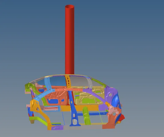
- In this project Simulation of Complete Side Pole Car Crash Rest is done on the given BIW of the car.
- For this project Only the distribution of forces and intrusion of the B-pillar, hinge pillar and fuel tank region and also at inner door peak velocity of the model has been calculated.
- Finally dervies the where are the most effected forces has been generated among those pillar regions.
STEPS TO FOLLOW THE CASE SETUP OF THE SIDE POLE CRASH;
- Check unit system and either follow [Mg mm s] or [Kg mm ms].
- Create appropriate interface ,friction 0.2 and recommended parameters.
- Make sure of no penetration and intersections.
- Create rigid wall with friction 0.1 as per referance model.
- Compare the model weight with the referance model and use added masses to reach target weight 700kg while getting CG about the required range.
- Initial velocity as shown in picture.
- Use model checker to ensure good quality.
- Timestep :0.5 to 0.1 microseconds.
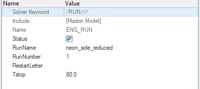
- Run 80ms.
Required Output requests:
- Sectional force in the cross member.
- Intrusion at B pillar,hinge pillar and fuel tank region.Provide recommendation on what can help to reduce Fuel tank intrusion.
- Peak velocity of inner node of the door.
- Check unit system and either follow [Mg mm s] or [Kg mm ms].
To check the unit system open the neon starter file in the notepad and were we can see the unit system below the Begin Card.

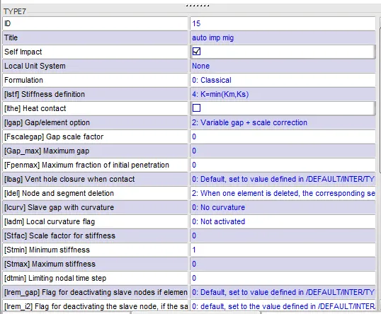
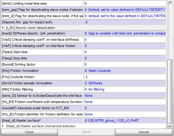
- Create an appropriate interface, friction 0.2, and recommended parameters.
For creating a contact or interfaces go to the hypercrash and we can set all the parameters of the type7 and mention with an friction value of 0.2.
- Make sure of no penetration and intersections.
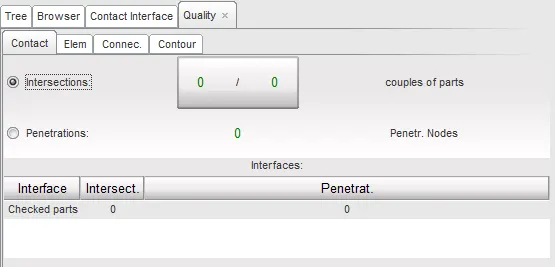
Compare to the hyperworks, checking the penetrations in the hypercrash is easy method.
Now after setting the interface card we need to check for penetrations and intersections if any. This can be done by opening HyperCrash under Applications. In HyperCrash we need to go for quality > select the check intersections of Tree selection and click this for penetrations and intersections check
- Create a rigid wall with friction 0.1 as per the reference model.
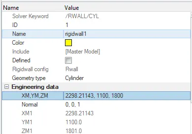
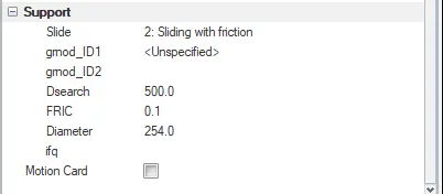
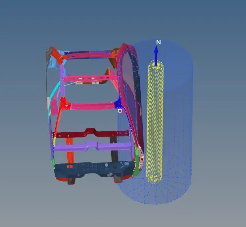
- Now we will be creating a rigid wall with friction 0.1. This can be done by load case and click a Rwall of the required type(cylinder).
For this side crash scenario, we are using a cylinder-type RWall.
set the parametrs for the Rwall
Search distance;500.
friction;0.1.
xm,ym,zm axis.
According the fedral motar vehicle safesty standards(fmvss), we consider the diameter of the cylinderical pole as 254.
Compare the model weight with the reference model and use added masses to reach the target weight of 700kg while getting CG about the required range.
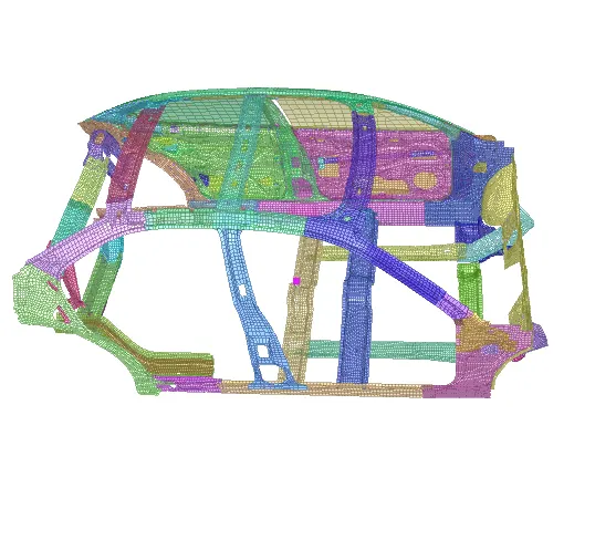
What is the importance of the CG? When making an analysis of the forces applied on the car, the CG is the point to place the car weight, and the centrifugal forces when the car is turning or when accelerating or decelerating. Any force that acts through the CG has no tendency to make the car rotate.
- To check for COG in the model Mass>Balancing
- A option called show C.G point only ,which will shows the the location of the COG.
- Here the total mass of the component is shown in the below.
- The total mass was found to be 188.42kg
- For balancing these mass we have to add mass and distribute among the components parts.
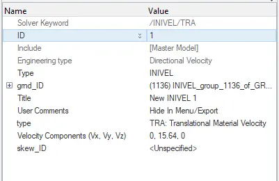
Initial velocity is shown in the picture.
This is done by creating an INVEL card go to the load case and click the invelocity and applying it to our model. As our unit system is in mm Kg ms so we need to convert 35mpH to given unit and it comes out to be 15.64mm/ms
The invel will given in the y direction inorder to move the model in an an y direction and also select the node id support for the model.
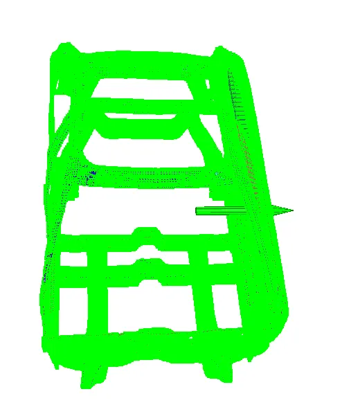
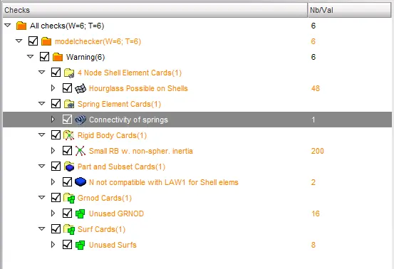
Use a model checker to ensure good quality.
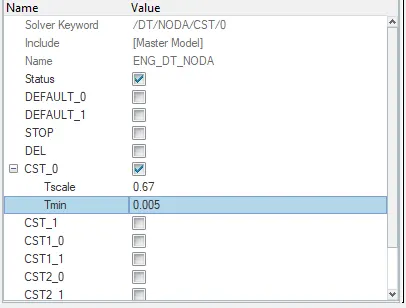
Timestep :0.5 to 0.1 microseconds
Run 80ms.
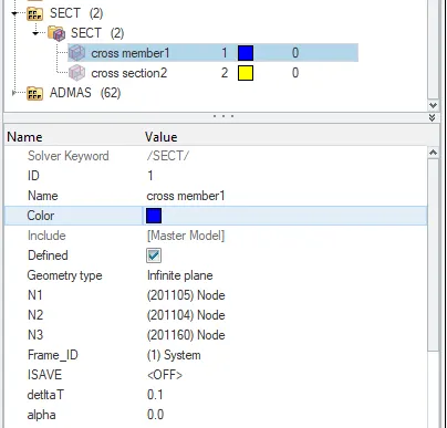
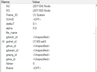
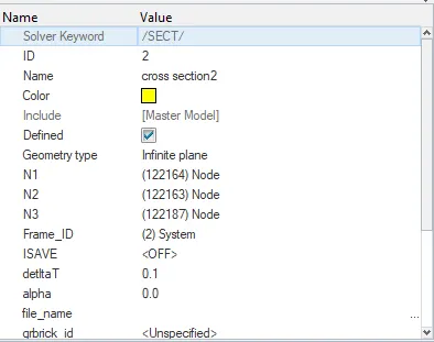
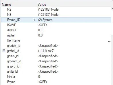
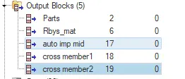
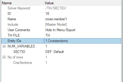
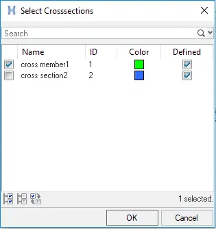
Sectional force in the cross member.
sectional cross member2
MOVING FRAME;
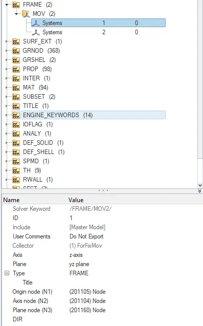
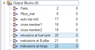
OUTPUT BLOCKS FOR SECTIONAL CROSS MEMBERS;
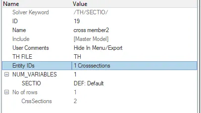
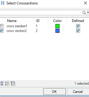
The intrusion at B pillar, hinge pillar, and fuel tank region. Provide recommendations on what can help to reduce Fuel tank intrusion.
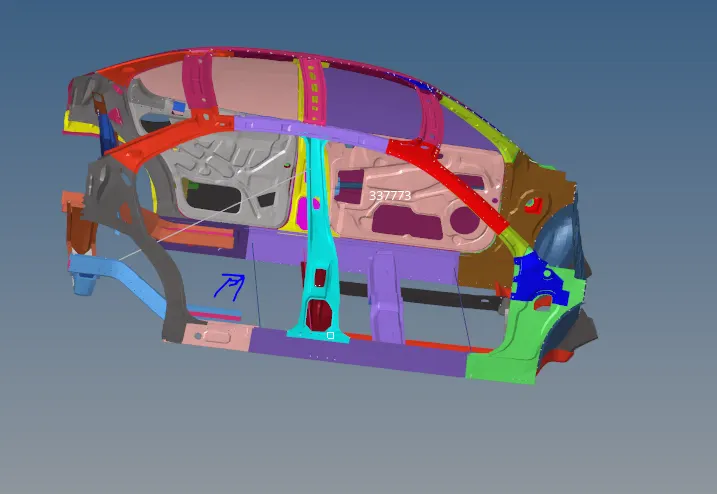
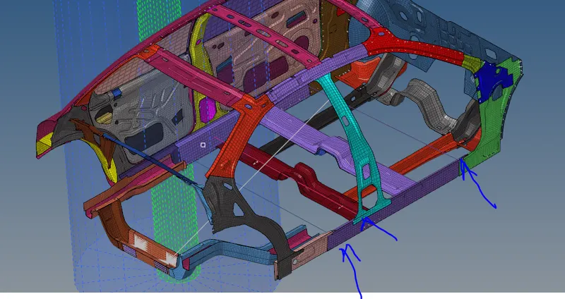
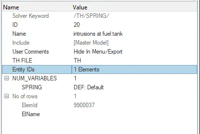
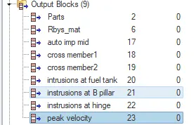
For ouput put results at intrusion B pillar, hinge pillar, and fuel tank region we have to create the 1D spring elements.
fuel tank
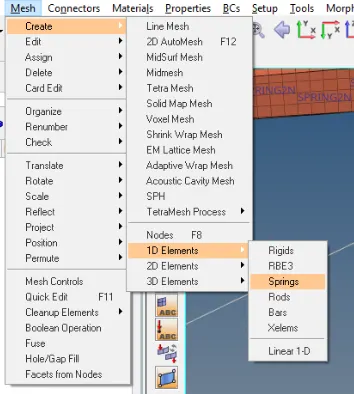
component

property

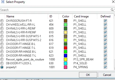
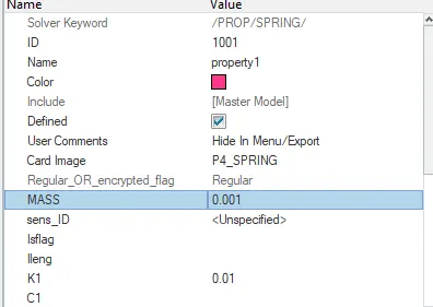
Create a seperate property and set the card image for the spring element component and make the changes on the parameters of mass and stiffness.
Assign these property to the particular component.
output block
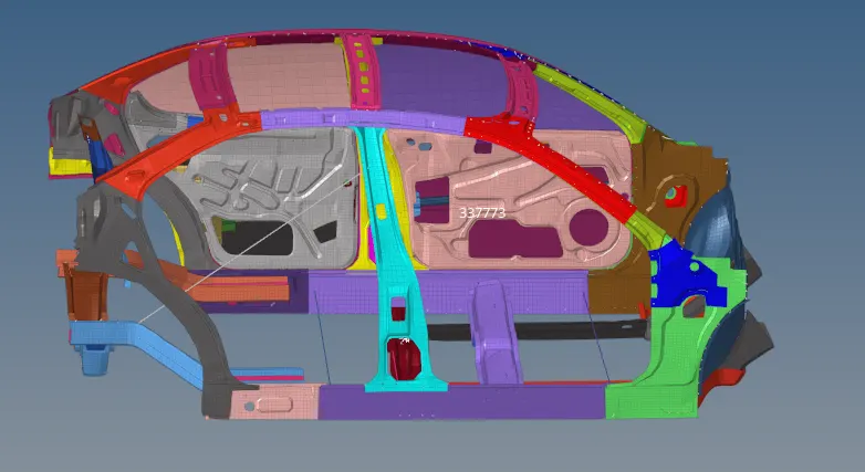
Peak velocity of an inner node of the door.
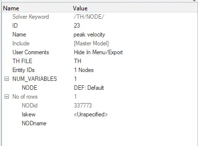
set the node at the Peak velocity of an inner node of the door.
Mention the entity id as node and create the Th_output for analyse the results.
Run the simulation and plot the graphs.
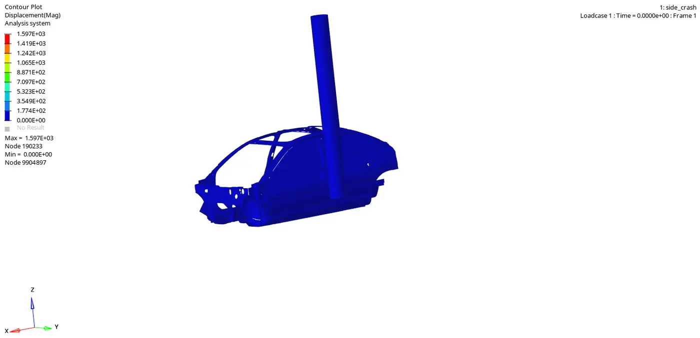
The maximum displacemennt occur in the side pole crash is 1.597E+03.
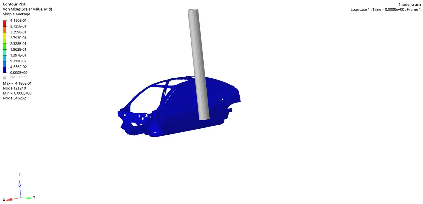
The maximum Von moises stresses recorded at 0.41GPA
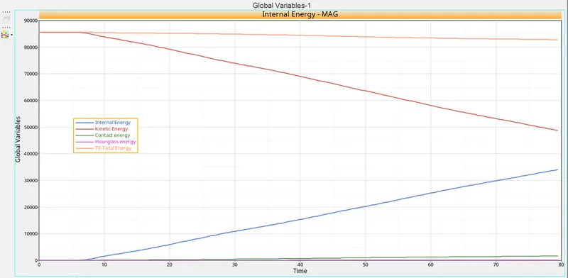
- The kinetic energy will increases from the starting and reduces as the velocity will comes to rest.
- As the Internal energy increases the kinematic energy decreases due to the conservation of the internal energy.
- The Hourglass energy is zero as we have given the QEPH Recommended shell elements to the propertites.
- The total energy is the addition of all the energies i.e TE=KE+IE+CE+HE
SECTIONAL FORCES AT CROSS MEMBERS;
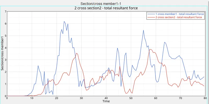
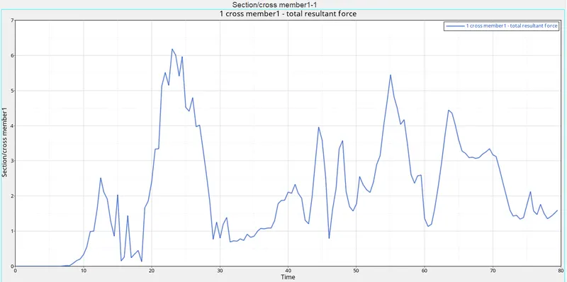
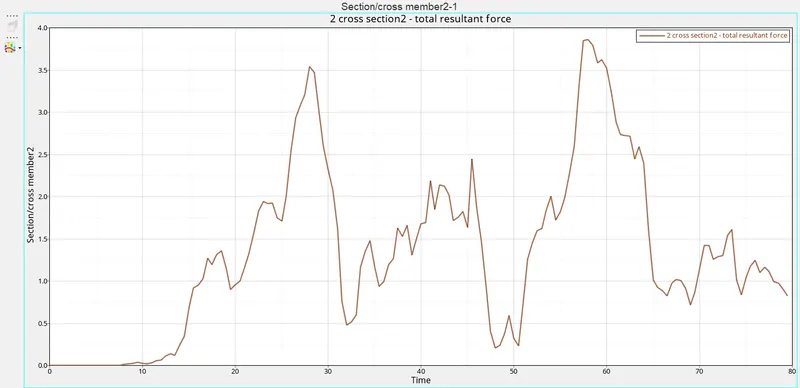
The 1cross member indicates at the Bpillar_cross member and the 2cross member indicated the front most cross member.
By observing the plot clearly we seen that forces are high(6.1kn) at the Bpillar cross member beause of the impact done on the most of the Bpillar section compare to the front cross member(3.8kn).
The intrusion at B pillar, hinge pillar, and fuel tank region. Provide recommendations on what can help to reduce Fuel tank intrusion.
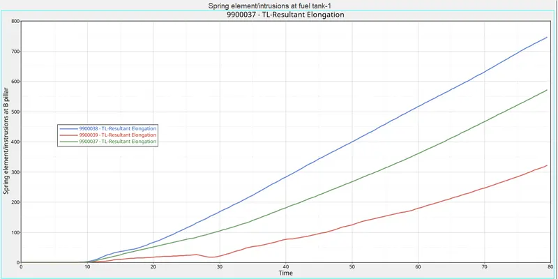
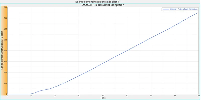
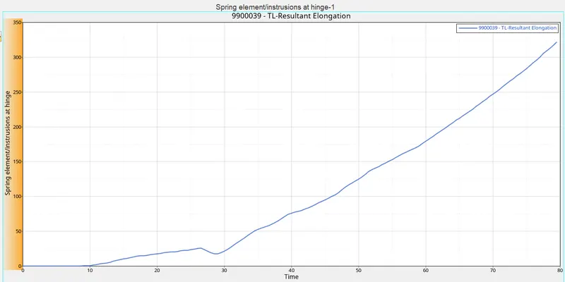
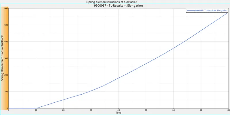
- Intrusion points at the B pillar, hinge pillar, and fuel tank region connected with the springs and added some mass and stiffness to the 1D spring elements.
- The spring element streaches as the time increases there is increase in displacement with respect to time
- Maximum displacement in B pillar can be seen at 80ms of 750mm.
- Maximum displacement in Hinge pillar can be seen at 80ms of 325mm.
- Maximum displacement in Bffuel tank region can be seen at 80ms of 600mm.
- Below we can see all the total resultant elongation of the three instrusion points.
B pillar
hinge pillar,
fuel tank region
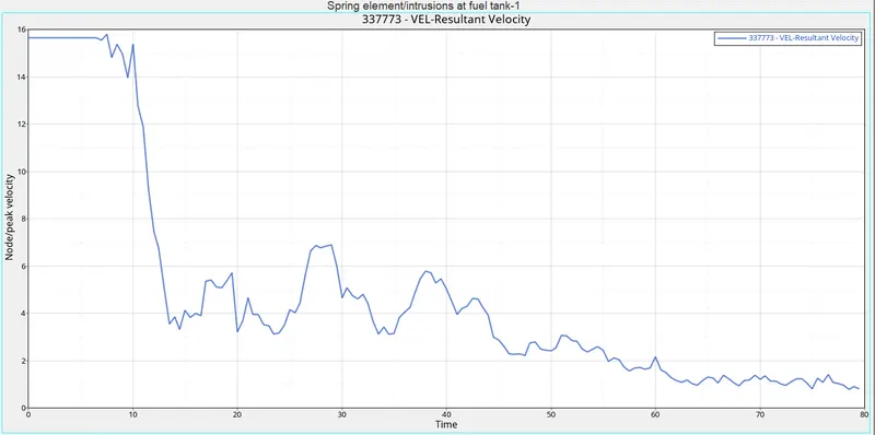
Peak velocity of an inner node of the door.
- select the node at the inner door of a model for calculating the peak velocity at the particular node point.
- velocity initially 15.8mm/ms at the inner door node.
- Then there is drop in velocity at 12ms it was due to side pole impact in B-Pillar direction and resultant forces.
- Again there is a small increase in velocity at 28ms of 6.5mm/ms
- After that velocity turns into a decrease at the 80ms.
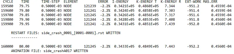
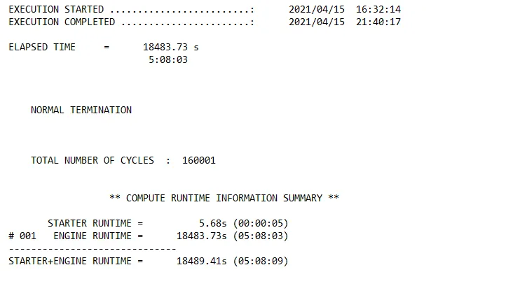
ENERGY ERROR;-2.2%
MASS ERROR;0.4560E-04
TOTAL NO OF CYCLES;160001
TIME;18483.73SEC
CONCLUSION;
Run the neon biw model for an side pole crash analyses.
Dervies the results from all the required parameters and graphs.
Check the energy errors and mass error of the simulation which is acceptable or not.
From the simulation we Observe that B pillar is the most effected to the crash and from that forces were distrubeted to the cross members and remaning parts of the body.
Peakvelocity of the inner door of the vehicle is also more, which is exposed to near B pillar.
drive link.