Assignment 7-Side Pole Crash Simulation Challenge
AIM: To perform side crash analysis on the given model using Hypermesh.
OBJECTIVE:
Neon side crash -BIW
- Check unit system and either follow [Mg mm s] or [Kg mm ms].
- Create an appropriate interface, friction 0.2, and recommended parameters.
- Make sure of no penetration and intersections.
- Create a rigid wall with friction 0.1 as per the reference model.
- Compare the model weight with the reference model and use added masses to reach the target weight of 700kg while getting CG about the required range.
- Initial velocity - 20mph, as per the standards.
- Use model checker to ensure good quality.
- Timestep :0.5 to 0.1 microseconds.
- Run 80ms.
Output requests:
- Sectional force in the cross member.
- Intrusion at B pillar,hinge pillar and fuel tank region. Provide recommendations on what can help to reduce Fuel tank intrusion.
- Peak velocity of an inner node of the door.
CASE SETUP & PROCEDURE:
Import the given .rad file using Import Solver Deck option as shown in Figure1. Figure2 and Figure3 shows the imported models of the given car model.
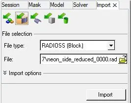 Figure1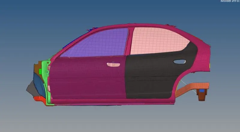
Figure2
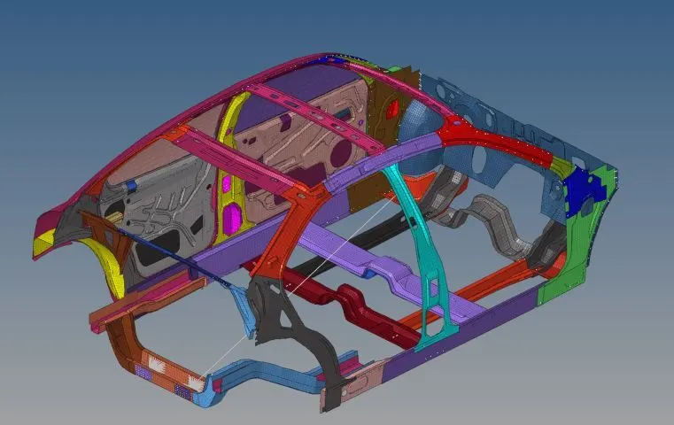
Figure3
- Check unit system and either follow [Mg mm s] or [Kg mm ms].
To check unit system Model>Cards>Begin_Card. Unit system for this model is [kg mm ms] which is shown in Figure4.
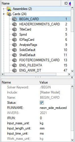 Figure4
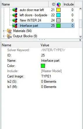 Figure5
- Create an appropriate interface, friction 0.2, and recommended parameters.
Since all the components of a model is self-impacting or the nodes and elements of the model will have a contact between we can create a Type7 interface. To create interface Solver Browser>Create>Inter>Type7 shown in Figure5. For Grnod_id(S) and Surf_id(M) select all the components as shown in Figure6 and select the recommended proprties and friction 0.2 as shown in Figure7&8.
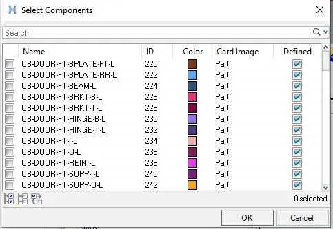 Figure6
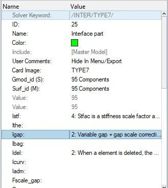 Figure7
 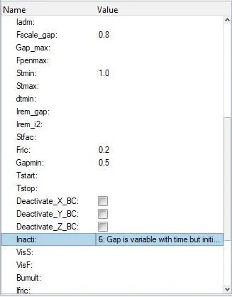 Figure8
- Make sure of no penetration and intersections.
To check for penetrations and intersections in the model, go to Tools menu on menu bar and click on penetration type for penetration check and intersection type for intersection and to check both penetration and intersection click on both, select components for entity type and select all the components as shown in Figure9&10.
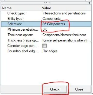 Figure9
 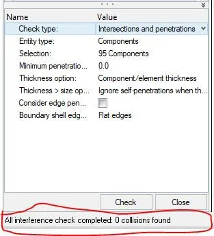 Figure10
- Create a rigid wall with friction 0.1 as per the reference model.
To create a cylindriical rigid wall with friction 0.1, side wise of the car. we need to create a plane for that we need a node from where at a distance of the the created plane rigid wall to be create. By using temp nodes option we will create a temperory node at the outermost of the side door of the car. To create rigid wall Solver Browser>Create>Rwall>CYL. For the location of rigid wall we will click on the node which we created and then give a certain gap in X-axix because the wall must not be connected to the mode and select the remaining parameters as shown in Figure11. Figure12 shows the model having rigid wall.
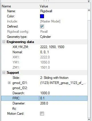 Figure11
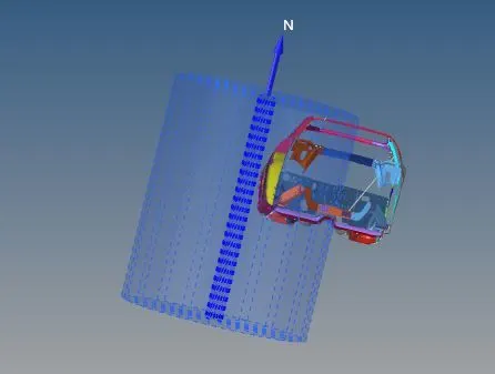 Figure12
- Compare the model weight with the reference model and use added masses to reach the target weight of 700kg while getting CG about the required range.
First check the mass and COG of the given model in Hypercrash for better visualization as shown in Figure13.
Here we will see that the mass of model is around 166 Kg and centre of gravity located as shown in the Figure13, but this is not in the case of main vehicle so we need to change the mass of vehicle to around 700 Kg and to get the COG in the middle of the model we have to add an extra mass.
To do that goto Solver Browser>Create>ADMAS. Select Mass is added to each nodeof node group, selected twenty nodes and added mass of 26.7 to each node inorder to total mass 700 (166+(20*26.7)) and nodes are selected in such a way that the COG of the model should be located at the centre of car sheet as shown in Figure14&15.
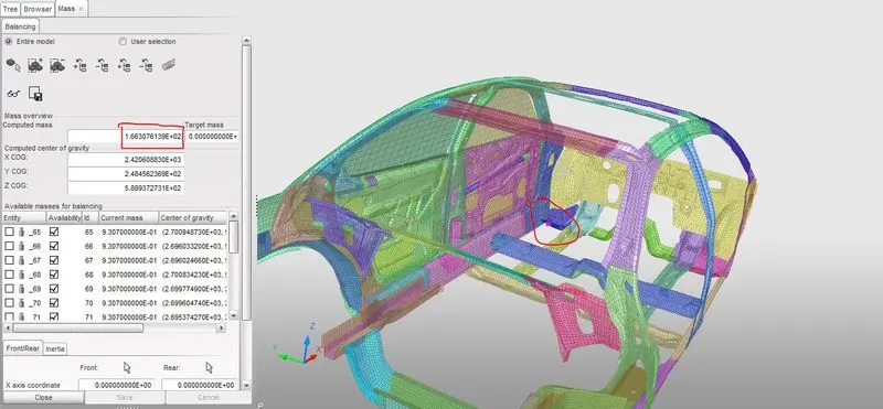
Figure13
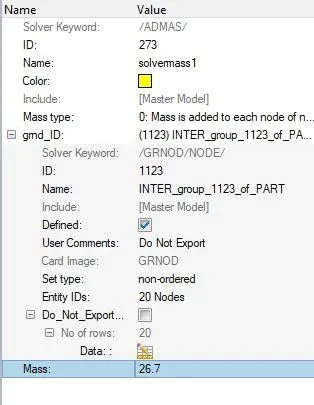 Figure14
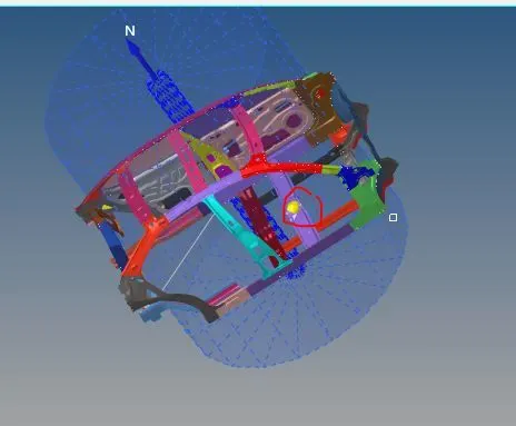 Figure15
- Initial velocity - 35mph, as per the standards.
To create Initial velocity Solver Browser>Create>Boundary Conditions>Inivel. Select all the components as the Entity for grnd_ID. We will give the initial velocity of 35 mph or 15.64 mm/ms in X-axis and as the velocity should be translational velocity, we will select TRA option in type as shown in Figure 16and17.
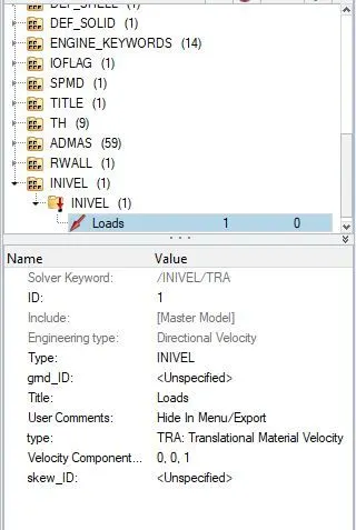 Figure17
 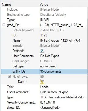 Figure18
- Use model checker to ensure good quality.
To check the quality, Menu Bar>Tools>Model Checker>RadiossBlock.
after clicking on RadiossBlock new model check browser will open in which if we click on Run Checks command which is at the top right side it will show all the errors the click on Auto Correct box in which the software automatically perform the possible corrections and give a green tick in status bar as shown in Figure19 and 20.
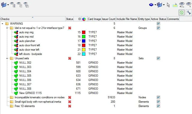
Figure19
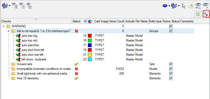
Figure20
- Time step and Run time
To check the run time, Model Browser>Cards>ENG_RUN>Tstop=80ms shown in Figure21
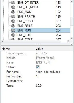 Figure21
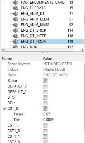 Figure22
To check the Run time, Model Browser>Cards>ENG_DT_NODA>Tmin=0.0005 ms as shown in Figure22
- Sectional force in the cross member.
To create cross sections where we will be calculating the results, we need to create a frame of reference at that location. The created moving frames which are also called as local axis have to be perfectly aligned with the global axis. So for this we will extract the node location or coordinates of a particular node on the section in Nodes panel, then we will offset the node in X-axis by 10 units and create a new node. Similarly we will offset the node in X-axis by 10 units and create a new node. Similarly we will offset and create a node in Y-axis as shown in Figure23.
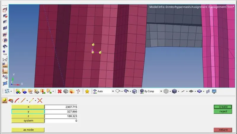
Figure23
We can use these nodes to create moving frames, Solver Browser>Create>Frame>Mov. Select the frame by node reference by selecting origin node and selcting the offset nodes for X-axis and XY-plane and click on create as shown in Figure24.
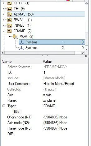
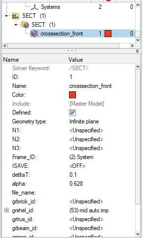
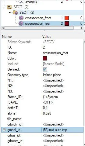
Figure24 Figure25 Figure26
After creating a moving frame then we have to create a cross section, To create cross section Solver Browser>Create>Sect.In section panel, we will specify the Frame_ID as the moving frame which we created and remaining values as shown in Figure25&26.
After creating the cross sections, we have to request the results at the cross sections that we created. For this Model Browser>Output Blocks>Create. Select crossseections at the Entity IDs by this we are able to plot graphs of the cross sectional forces in HypeerGraph as shown in the Figure27&28.
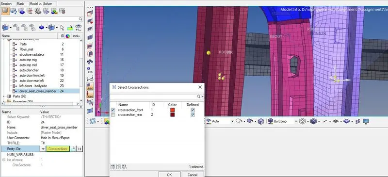
Figure27
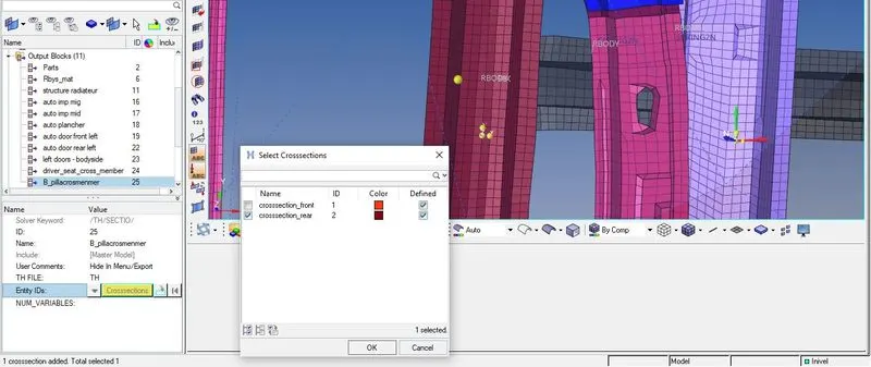
Figure28
- Intrusion at B pillar,hinge pillar and fuel tank region. Provide recommendations on what can help to reduce Fuel tank intrusion.
Here, we need to find the intrusions at B-pillar, hinge pillar and fuel tank. So to find the results at the specified prts we need to create spring between left and right parts of B-pillar, Hinge-pillar and fuel tank. To create spring goto 1D>SPRINGS>SPRING2 and select 2 nodel as shown in Figure29&30.
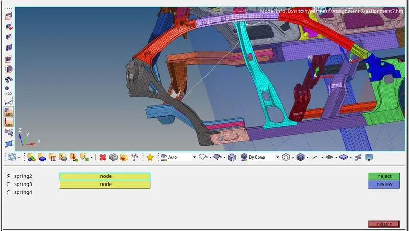
Figure29
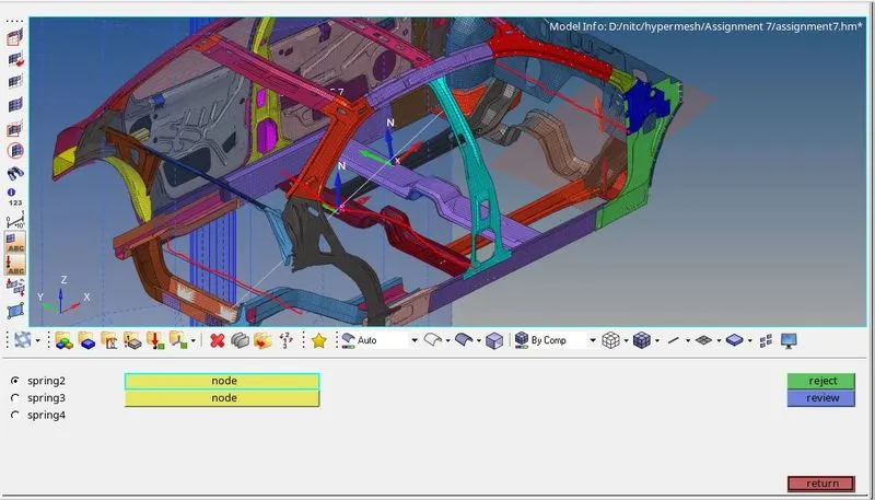
Figure30
Now we have to create property card for spring and assign it to the spring element created.Goto MODEL BROWSER>CREATE>PROPERTY>RENAME AS INTRUSION SPRINGS. After creating a property a new tab will open there we have to select CARD image as P4 SPRING and Mass as 0.001 and Stiffness K as 0.001.
After creating Instrusions we need to create outputs, Inorder to measure intrusions on the spring we have to go SOLVER BROWSER>CREATE>TH>SPRING, then select the entity ID is spring element created at each position as shown in Figure31&32.
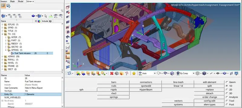
Figure31
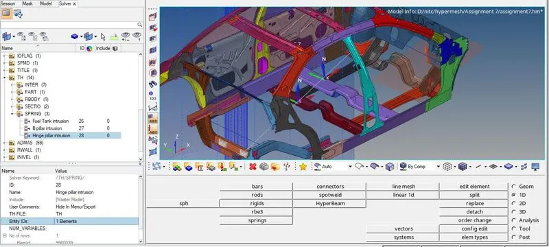
Figure32
- Peak velocity of an inner node of the door.
To find the peak velocity at the inner node of the door, we will create a moving frame at the node location by using SOLVER BROWSER>CREATE>SKEW>MOV.Select the required node as origin node then select node to define x-axis and XY-plane as shown in Figure33 and to request output MODEL BROWSAR>Create>OUTPUT BLOCKS. The entity ID is going to be just the one node- node 337773 and for Iskew, we shall be selecting thescke created previouly.
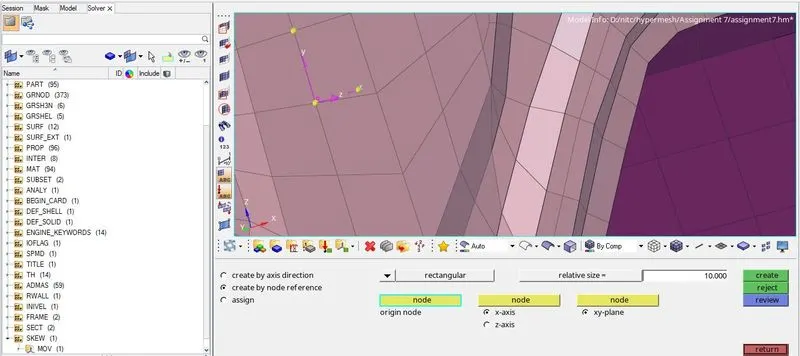
Figure33.
RESULT & SIMULATION:
First we will check the energy error and mass error for this we have to open the engine.out file of the model and check the last column for energy and mass error as shown in Figure34.

Figure34
Energy Error : -1.3%
Mass Error : 0.5461E-03
Total number of Cycles : 160001
Total runtime : 5746.97s
To visualise the animation results we can navigate to HyperView section in which we will import .h3d file and load the model, Here we can able to simulate and animate the results of the model.
Crash simulation files are uploaded as video1.mkv and video2.mkv.
The deformations in the model is unrealistic since the given model is not complete at the same time i added the extra mass to ten nodes inorder to increase the total mass of the car which is totally responsible for this unrealistic deformations in the car.
To view graph result we can directly shift to HyperGraph 2D in which we will load the T01 file and plot the results for different parameters which is shown below Figures35,36,37&38.
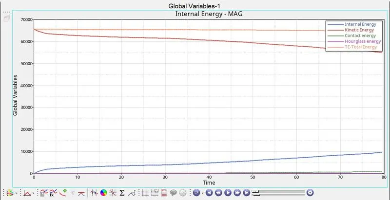
Figure35
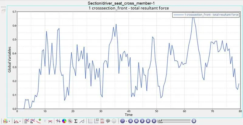
Figure36
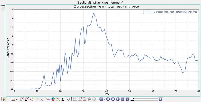
Figure37
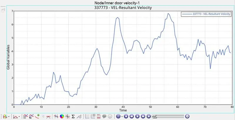
Figure38