Assignment 7-Side Pole Crash Simulation Challenge
Obhective :
- Performing the Side crash analysis of the Neon Vehicles Model and studying the all energy plots for the same .
- Creating the appropriate interfaces with recommonded parameters .
- Checking for the no penetration and intersections.
- Create a rigid wall with friction 0.1 as per the reference model .
- Compare the model weight with the reference model and Add some masses to reach the target weight of 700kg while getting CG about the required range.
- Setting the Initial velocity of 35 mph , Timestep to 0.5 microsecond and Run time of 80 milisecond .
Theory :
Body in white (BIW) is the stage in Automobile Manufacturing in which a car body's frame has been joined together, that is before painting and before the motor, chassis sub-assemblies, or trim (glass, door locks/handles, seats, upholstery, electronics, etc.) have been integrated into the structure. Assembly involves different techniques such asWelding (spot, MIG/MAG),Rivating , Clinching , Bonding and laser Brazing
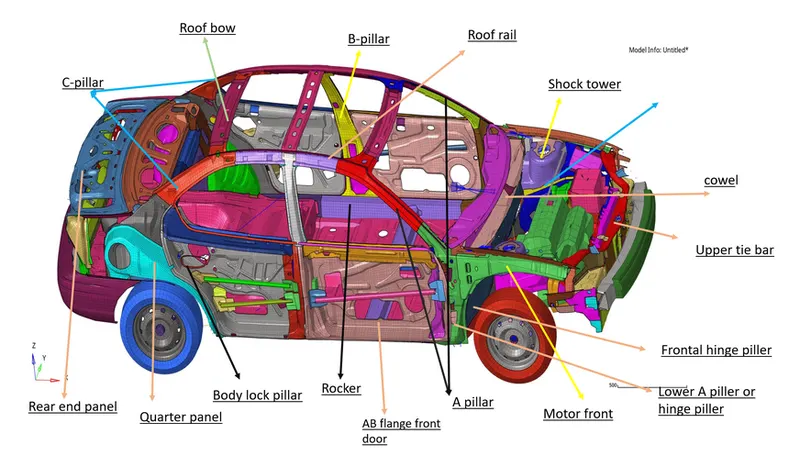
Parts :
A piller : Front Most support to the Roof .
B piller : Second most support to the Roof .
C piller : It is rear most support ; In case of the 2 seating system it wiil be 3rd one .
D piller : It is Forth support to the roof can be find the near rea side of quater panel .
Roof Header : Structural member above the windshield at the juncture with the forward edge of the roof panel .
Shotgun : Main structural Member of the BIW which absorb Crash energy , support battery and other parts , Transfer shock load from shock tower to Body .
Bumper : A horizontal bar Fixed at front and back side of the vehicle to reduce the damage in collision .
Rail : Located just behind the Bumper and absorb the crash energy after the Bumper .
Section : It is representation of the cross members of the vehicle.
Procedure :
- Model's Rad file is imported by setting up the Radioss Block as user profile .
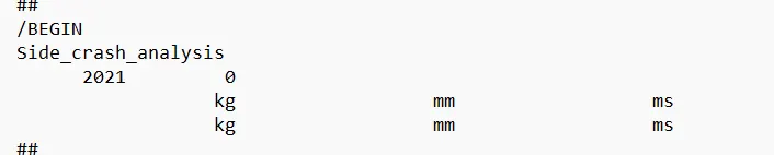
- The Unit system can be identified by the Starter file for our convenieance .
- Here we are following the Kg , mm , ms and KN unit system .
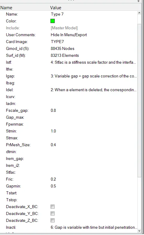
- For getting the proper results we have to define the proper Interfaces .
- Here Other unwanted interfaces are deleted and type 7 of interface is created for all the parts with proper recommonded parameters .
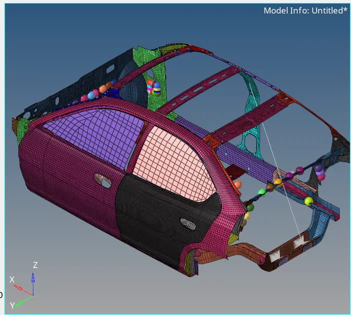
- For checking the penetrations and the intersections , Penetration checker is used .
- There wasn't any penetration and the intersection observed .
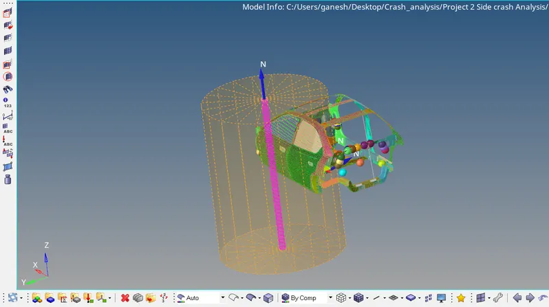
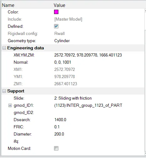
- Rigid wall is created with the friction of 0.1 , 1400 of search distance and 200 mm diameter of pole as .
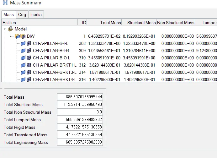
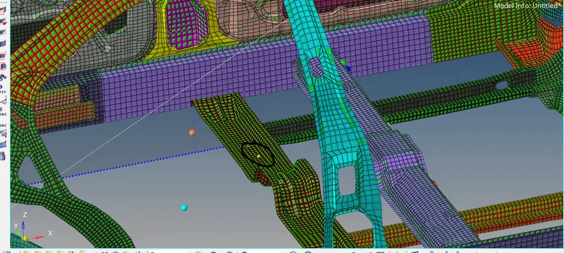
- For achiving the Targetd Mass of the model of 700 Kg , some masses are added to the respected parts location .
- while adding the masses , Center of gravity is kept in mind that it should be loacted at the Idela location of saftey of the occupants inn the Vehicle .
- Masses of the Differential , Transmission shaft , Front seats and the rear seats are added to the respecyted location .
- After adding the masses the total weight of the vehicle is 686 kg now .
Total Mass : Center of Gravity :
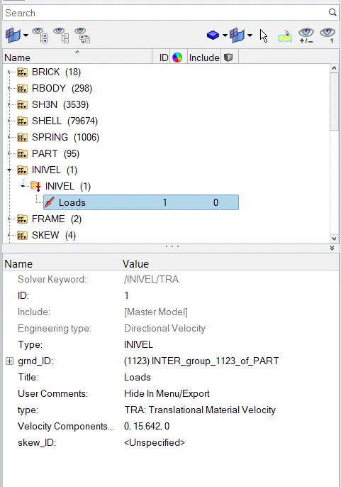
- Initila velocity of the 35 mph is applied to all the parts of the vehicles , by converting this velocity mph into the mm/ms unit system of 15.64 mm/ms in Y-axis direction .
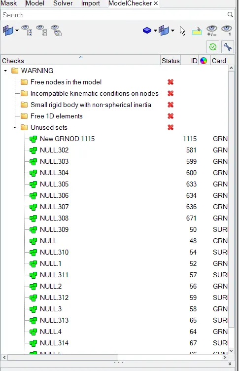
- Model Checker is used to ensure the Good Quality of the model .
- here no any error is highlighted only wanrning are shown , which can be ignored some time .
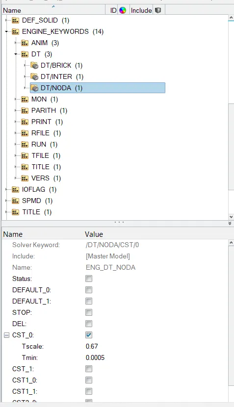
- Time step of 0.5 microsecond is applied at DT/NODA at Tmin as ,
- The Total simulation time setted to the 80 milisecond at ENGINE RUN Card .
Output Request :
- For Getting the Forces at Cross members of the model ,sections are created defining the N1 , N2 , N3 and frame id and the grshell_id at both Cross members as ,
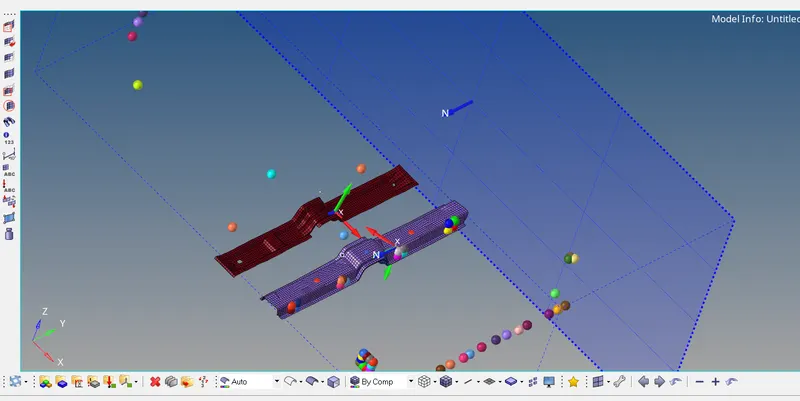
- For getting the intrusion at indicated node locations i.e. at Front Seat base , Middle cross member and at fuel tank Location .
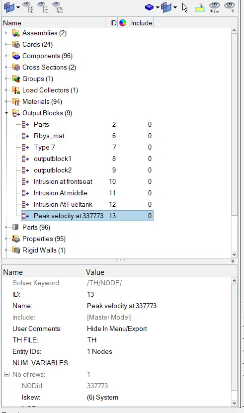
- Output blocks are also created for requesting the this intrusion as output in the form of graph .

- Now for getting the Peak velocity at the Inner node of the door of front seat , output block is created .
Results :
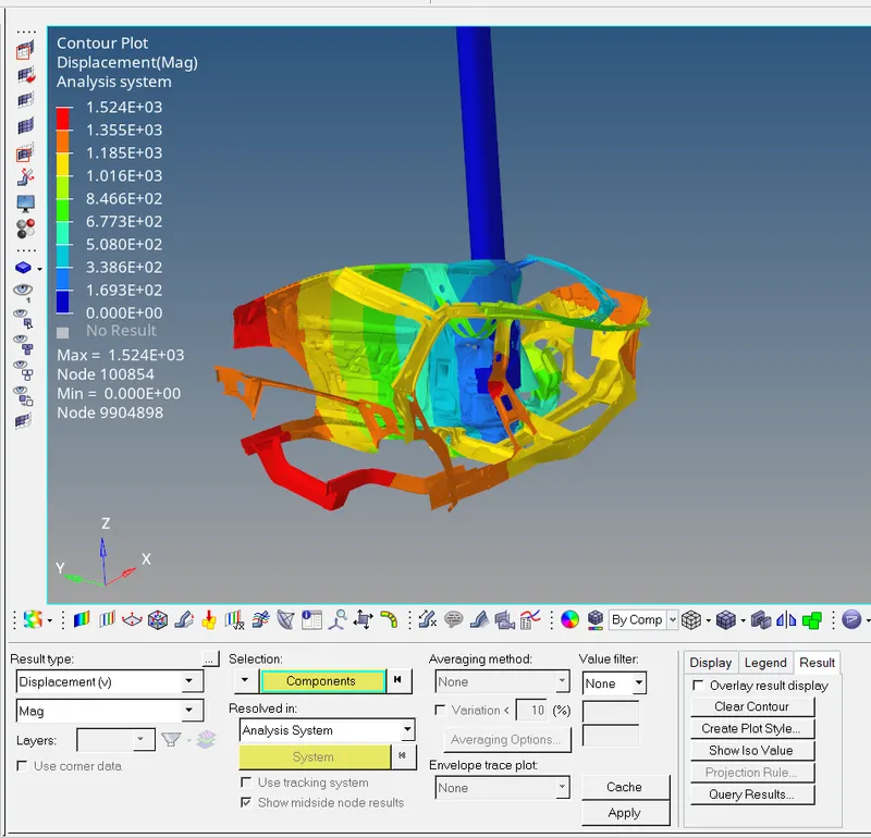
- Displacment contour :
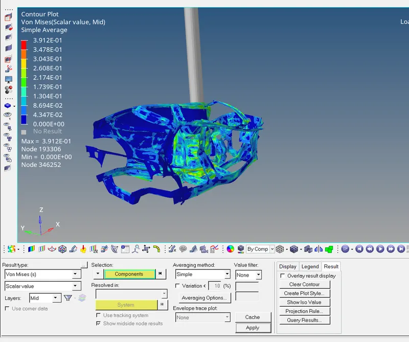
- Von-misses stresse contour :
Energy plot :
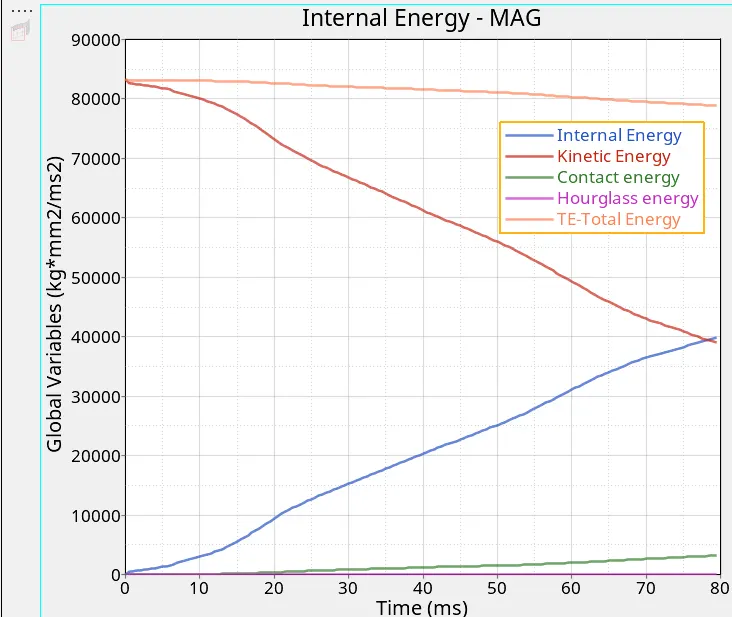
- From graph is can be seen that the Kinetic Energy is High at Starting Of crash and decrease after the crash happens .
- The Kinetice Energy decreases with increase in the internal energy .
- This kinetic Energy is get converted into the Internal Energy
- The Hourglass energy is in the range of the 5 % of the Total Energy .
- This hourglass energy is much stabalized as we have improved the shell properties to the recommonded .
- The Total energy is Almost Constant , which is Good Sign of Energies Balance .
Sectional Forces in the cross members :
Middle cross member : Front seat base cross member :
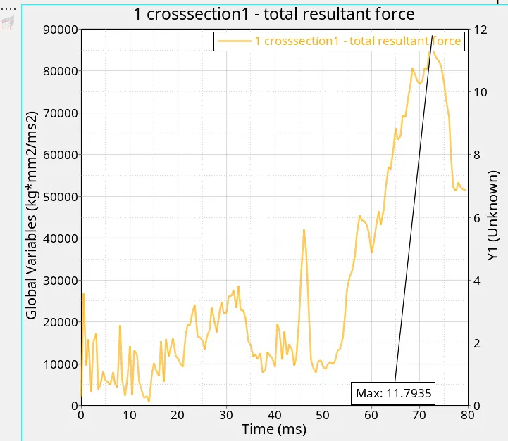
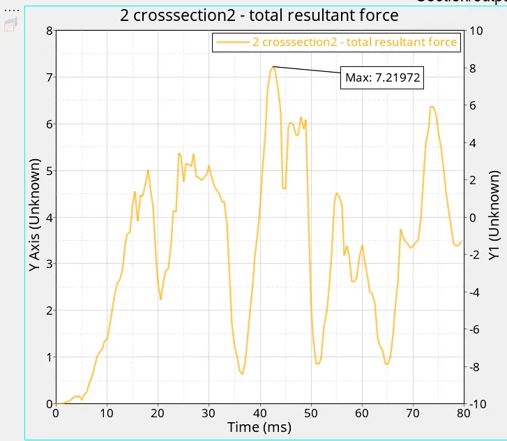
- The Maximum force can be observed at 1st cross member than the 2nd cross member .
- This More force in 1st cross member than 2nd cross member is because of the More mass is distributed and the location of the Pole towards the 1st cross member .
- Center of gravity will also affect the Forces in the cross members .
- The Froce in the 1st cross member is 11.7935 KN and in 2nd Cross member is 7.21972 KN .
Intrusion At Indicated Node locations :
Intrusion at Hinge Piller :
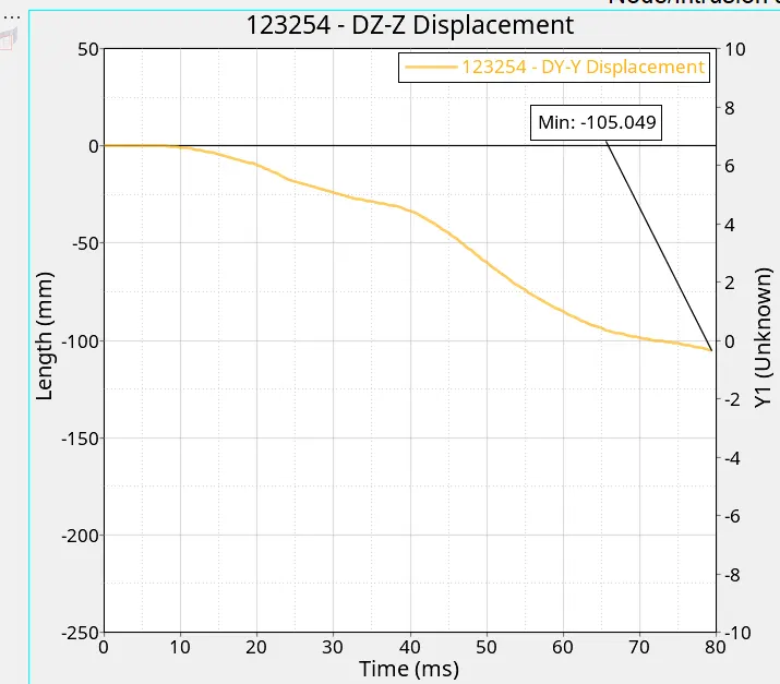
- From graph it can be clearly seen that the Intrusion at front seat is about -105.049 mm .
- Negative sign indicates that the intrusion happed in negative Y axis direction .
Intrusion at the B piller cross member :
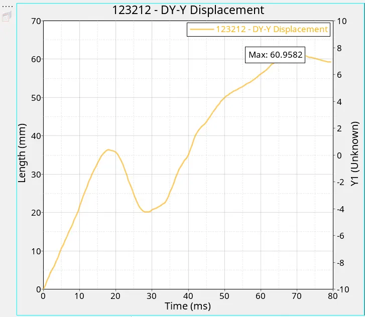
- From Graph we can see that at Middle cross member the intrusion happened in positive .
- This Positive intrusion indicated the intrusion happened in Positve Y-axis direction .
- This intrusion is of 60.96 mm.
Intrusion at the Fuel tank location :
- In above graph , Intrusion at fuel tank os about -71.48 mm
- This negative sign indicats that the intrusion here happened in the Negative direction .
- The intrusion reduction at Fuel tank location can be achived by adding extra cross member at the Fual tank location , as we can see in the model that there is no any cross member is provided .
- An extra Cross member at fual tank location will absorbe the forces .
- after the side crash , this cross member will help in reduction of the forces applied at that perticular location and hence will results in less intrusion at fuel tank location .
- The peak Velocity of the Indicated node inside front seat door can be seen in below graph as .
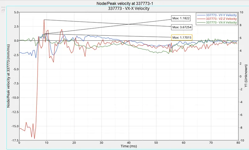
- Peak velocity at indicated node form inner side of the Front door is 1.18 mm/ms in X-axis direction , 1.170 mm/ms in Y-axis direction and 3.67254 mm/ms in Z-axis direction .