Assignment 7-Side Pole Crash Simulation Challenge
Aim: To simulate Side Pole Crash for the given model.
Neon side crash -BIW
- Check unit system and either follow [Mg mm s] or [Kg mm ms].

- Create an appropriate interface, friction 0.2 and recommended parameters.
Type 7 contact was defined and the recommended parameters were defined in the model. The previously defined contact parameters were removed from the simulation.
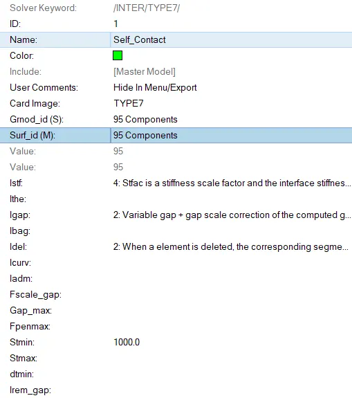
- Make sure of no penetration and intersections.
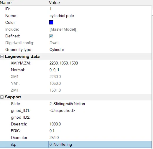
- Create a rigid wall with friction 0.1 as per the reference model.
The cylindrical rigid wall was created using Cylindrical rigid wall option.
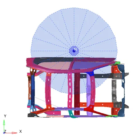
- Compare the model weight with the reference model and use added masses to reach the target weight of 700kg while getting CG about the required range.
Mass Balancing
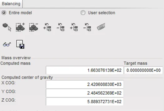
It was determined that the existing mass of the system was 166.30kg but the instructed weight is about 700kg. Thus, there is a need to add the required mass into the body.
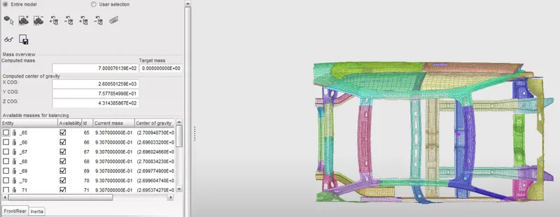
Mass was added to the required locations and was brought to 700kg.
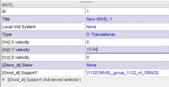
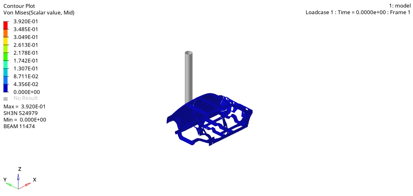
- Initial velocity as shown in the picture: initial velocity of 15.64mm/ms was defined in the y-direction to all the nodes in the geometry.
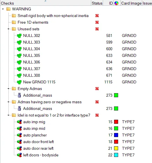
- Use a model checker to ensure good quality.
Model Checking: No prominent error was determined.
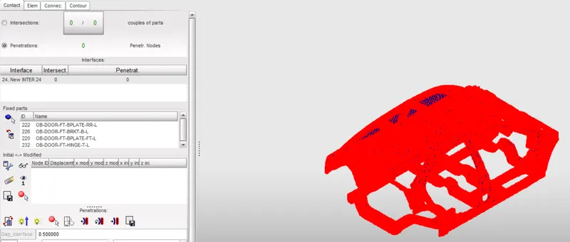
Using the Contact Interface option under the LoadCase option, the complete body was selected and the penetration check was established. No Penetration and Intersection was determined in the model.
- Timestep :0.5 to 0.1 microseconds.
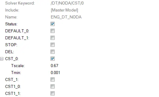
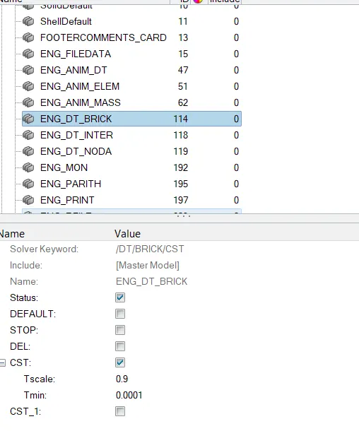
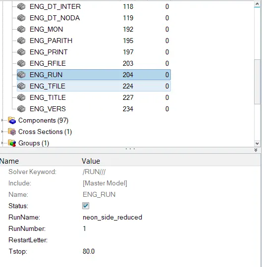
- Run 80ms.
Results:
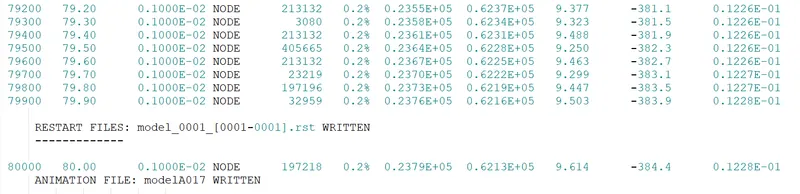
From the output fle it was observed that both the energy and mass error were obtained within the accepatable limit.
Animation
Energy Variation Plot
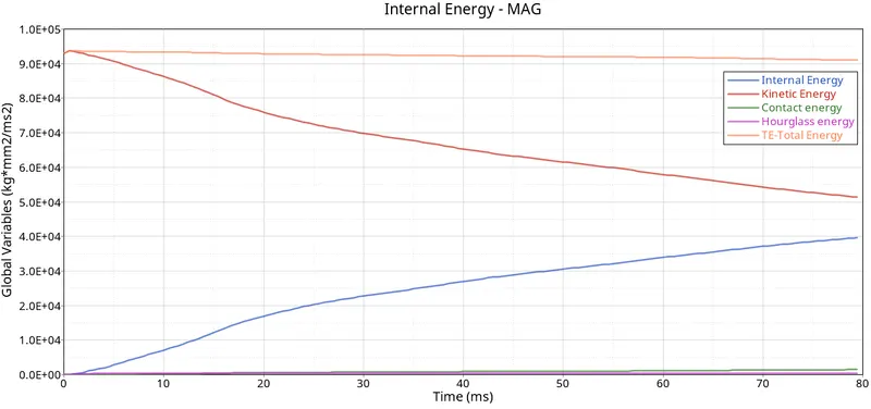
Negligible losses were observed from the model and with a gradual reduction in the Kinetic Energy, there was subsequent energy rise observed in the Internal Energy of the system.
Peak Velocity Plot for the inner door
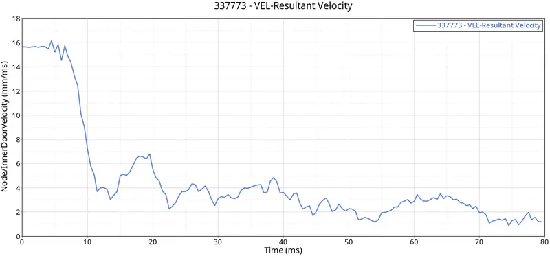
A maximum velocity of 16.15mm/ms2 was obtained at 4.5ms. At the impact phase, the body experiences higher acceleration but gradually due to plastic deformation of the strucutre, huge amount of energy is absorbed and subsequently a steep drop in the velocity is observed in the curve.
Sectional Force of the Cross Member
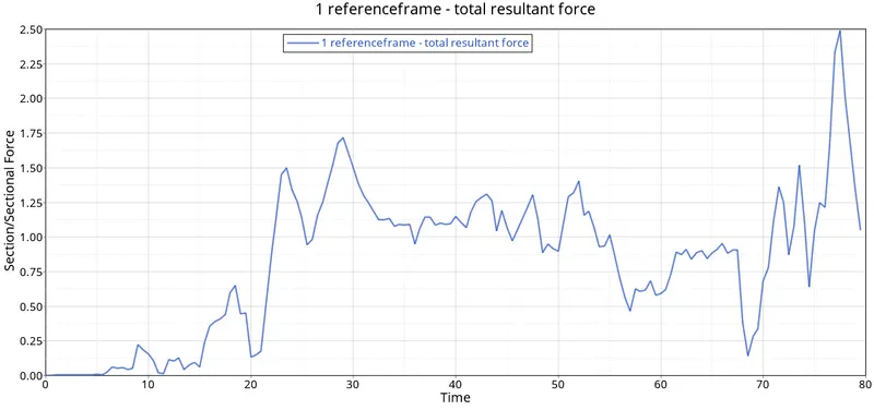
The maximum force obtained is about 2.45kN at 77.5ms in the driver seat crossbar.
Intrusion plot Comparision
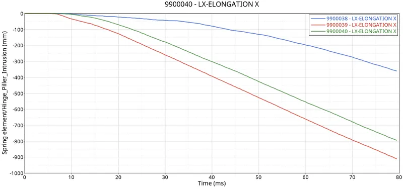
In the given figure:
9900038 represent = Hinge Piller
9900039 represent = Fuel Tank
9900039 represent = B Piller
Conclusion:
- The given model was checked and required changes were made to obtain the desired result.
- It was determined that the intrusion near the fuel tank could be reduced by adding additional reinforcing members like crossbars which act as stiffeners adding extra rigidity to the structure.
- Maximum displacement was observed in the B pillar and Fuel tank link when compared to Hinge Piller at a given point of time.
- The maximum force obtained is about 2.45kN at 77.5ms in the driver seat crossbar.
- Peak velocity of an inner node of the door was 16.15mm/ms2 was obtained at 4.5ms.