Assignment 7-Side Pole Crash Simulation Challenge
Objetive and Motivation: Side Pole Crash Simulation
We will simulate the side pole car crash with using RADIOSS (solver) under Hypermesh/Hypercrash (preprocessing) as seen in the below figures.
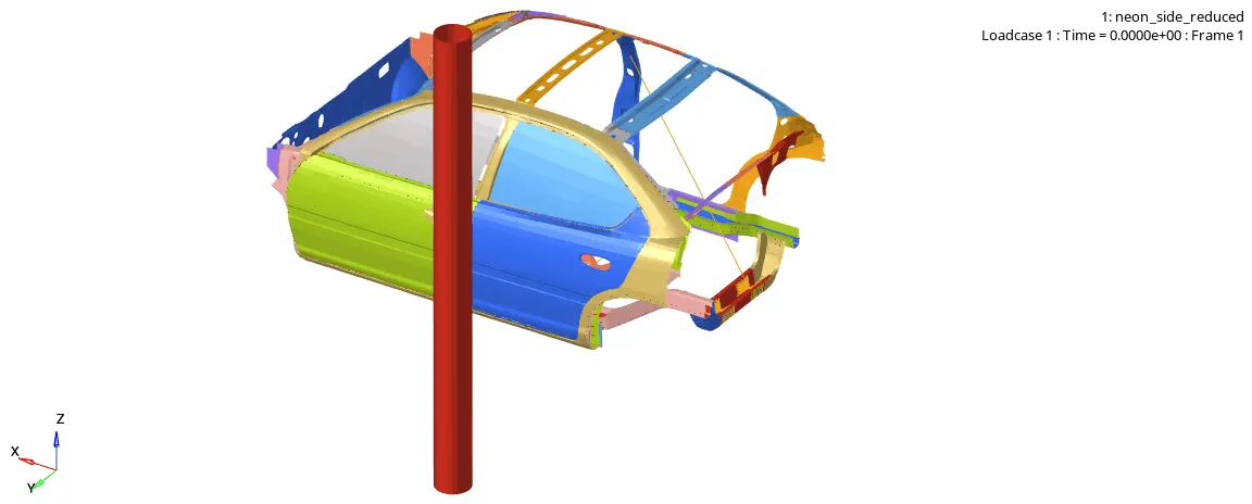
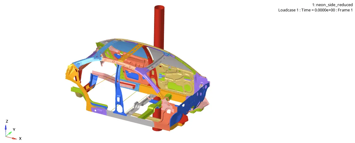
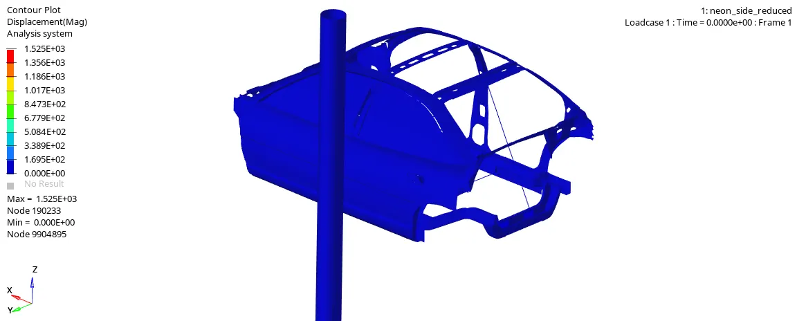
- To check unit system and either follow [Mg mm s] or [Kg mm ms].
- To create appropriate interface, friction 0.2 and recommended parameters.
- To make sure of no penetrations and intersection.
- To create rigid wall with friction 0.1 as per reference model
- To compare the model weight with reference model and use added masses to reach target weight 700kg while getting CG about the required range.
- To set an Initial velocity 35 mph.
- To use model checker to ensure good quality.
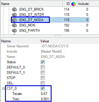
- To set time-step: 0.5 to 0.1 microseconds
- Run 80 ms.
Output requests:
- Sectional force in the cross member
- Intrusions at B pillar, hinge pillar and fuel tank region. Provide recommendation on what can help to reduce Fuel tank intrusions.
- Peak velocity of inner node of the door
Note:
- Submit your simulation files including time and h3d files.
- Plot energies and notice any difference.
- Explain your errors and how to rectify?
1) To check unit system and either follow [Mg mm s] or [Kg mm ms]
We will open the neon_side starter file with notepad which is given as neon_side_reduced_0000.rad to check unit system.
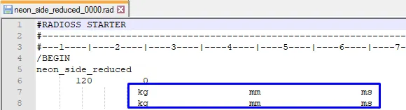
Figure 1: Unit system is recommended as kg mm ms
2) To create appropriate interface, friction 0.2 and recommended parameters
We will import the neon_side starter file in Hypermesh which is given as neon_side_reduced_0000.rad to set interface, friction and recommended parameters.
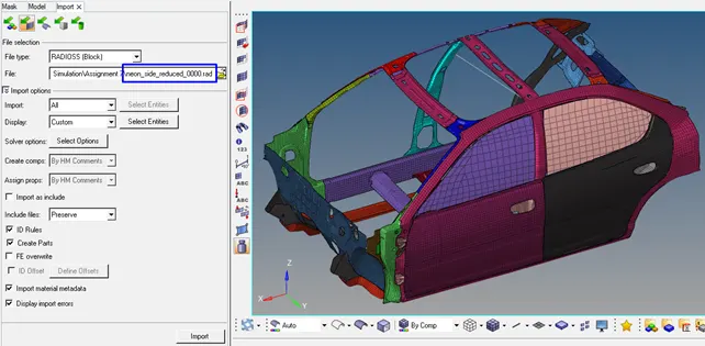
Figure 2: imported model
Recommended Parameters
/INTER/TYPE11: This interface simulates impact between edge to edge or lines. A line can be a beam or truss element or a shell edge or spring elements. This interface can be used in addition to /INTER/TYPE7 to solve the edge to edge limitation of interface TYPE7. Therefore, we will change Inacti to 6 in the INTER under Type7 in solver (figure 3) and /TH/PART is created.
The interface (/INTER/TYPE11) properties are:
- Impacts occur between a main and a secondary line.
- A secondary line can impact on one or more main lines.
- A line can belong to the main and the secondary side. This allows self-impact.
- One of the drawbacks of type 7 contact is that it cannot remove the element intersection that is present in the model.
- To avoid that kind of issue and edge related intersections, Type 11 contact is preferred.
- Type 11 works very much similar to that of type7 but the search is for only the edges of the model.
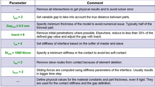
Figure 3: Recommendations for Crash Applications for Interface Type7 and Type11
To set recommended Crash properties for Type7 and Type11, we will first delete Interfaces that were predefined.
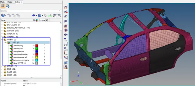
Figure 4: predefined Interfaces
We will select all of the components for Gmod_id (slave) and Surf_id (master) on the Entity IDs.
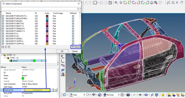
Figure 5: Gmod_id (S) 95 Component selected
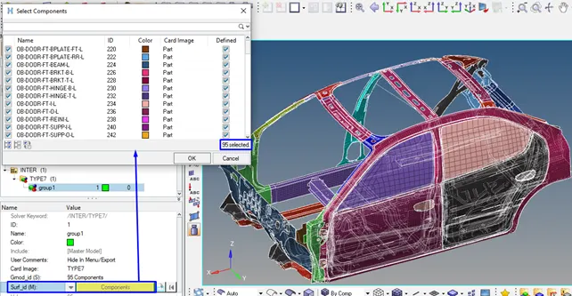
Figure 6. Surf_id (master) 95 Component selected
Recommended Crash properties
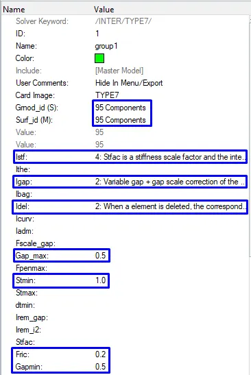
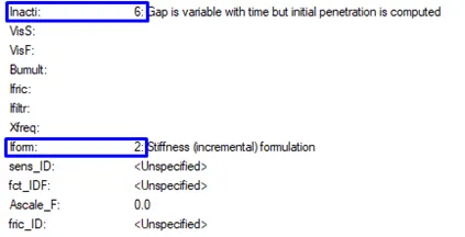
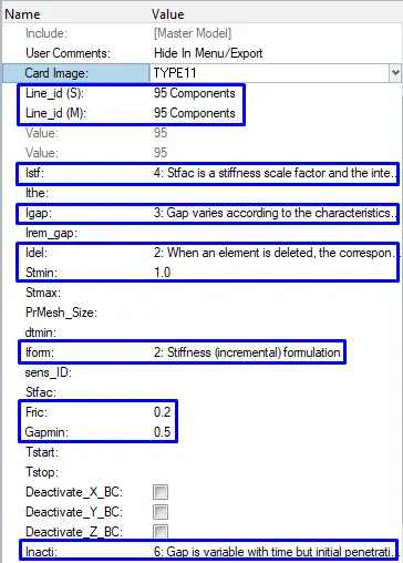
3) To make sure of no penetrations and intersection
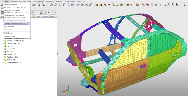
We check Intersections from Quality on the Hypercrash.
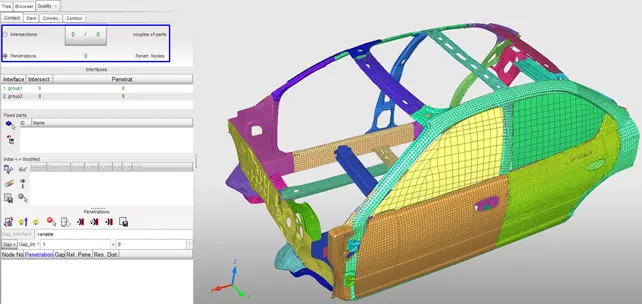
There are no penetrations and intersections in the figure below.
4-5) To correct rigid bodies if any issues and create rigid wall with friction 0.1 as per reference model
Rigid Wall (/RWALL)
A rigid wall is a nodal constraint applied to a set of secondary nodes in order to avoid the node penetration to the wall. If contact is detected, then the secondary node acceleration and velocity are modified.
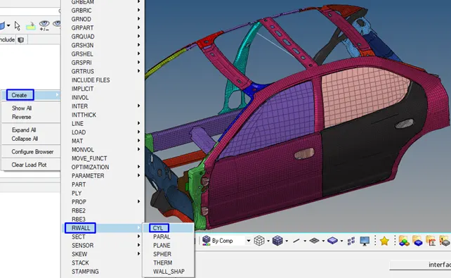
We will create RWALL> CYL on the Solver.
We will create a reference node to set a RWALL. Therefore, a temp node is created in the middle of the door. After creating of the temp node, it is 50mm translated in Y- direction.
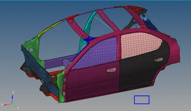
Figure 9: translated node
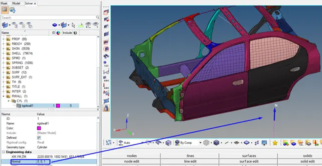
We will select with arrow translated node in Engineering Data to set coordinates XM, YM, ZM.
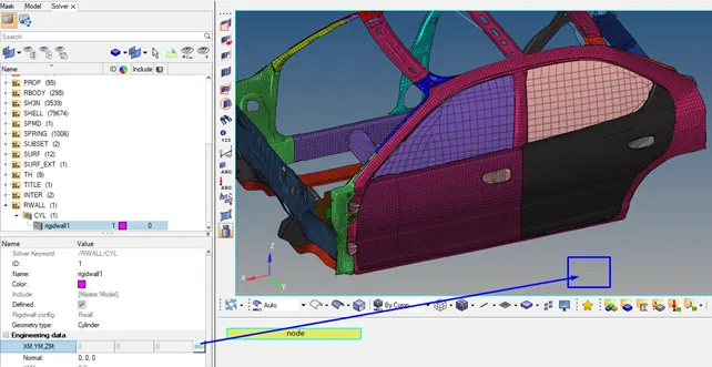
Figure 10: translated node that is selected to create RWALL
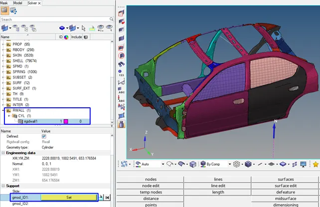
We need a new set for grnod_ID1.
We create Node from GRNOD.
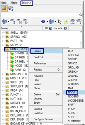
We will select all of nodes of the model under the rename Complete_Node_CAR.
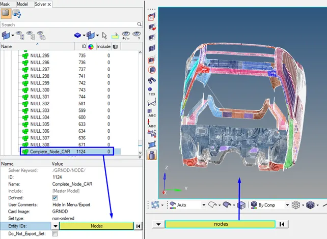
Complete_Node_CAR will be selected in the gmod_ID1
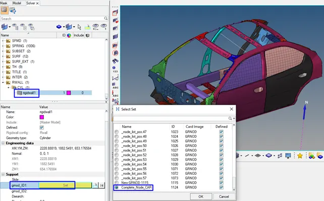
Contact occurs only when the secondary node impacts the rigid wall surface. The secondary node's tangential velocity can also be modified depending on the flag Slide. The default value (=0) enables the model pure sliding during contact. If set to 1, no sliding is allowed, the secondary nodes are "tied" in the tangential direction. If set to 2, friction based on Coulomb model is enabled. Dsearch is defined as “Distance for secondary search”, all the nodes within this distance will be considered as slave nodes for the contact between the car and the rigid wall.
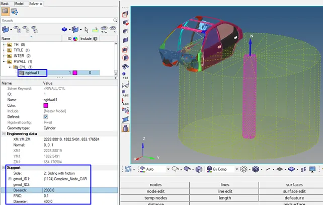
Figure 11: RWALL is created
6) To compare the model weight with reference model and use added masses to reach target weight 700kg while getting CG about the required range.
We will open Balancing on the Mass to check center of gravity and mass of the model.
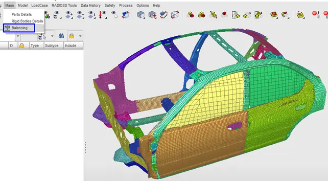
Model is 166kg
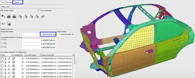
Center of mass
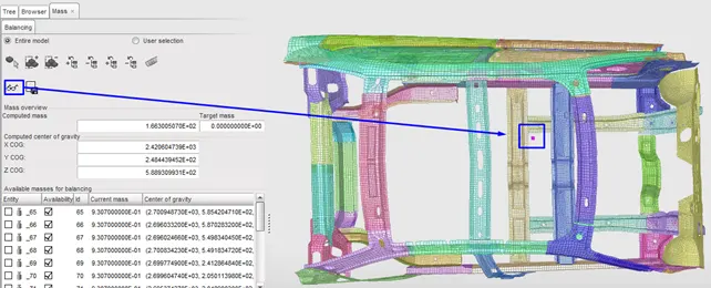
Current weight is 166kg and we will add mass to reach 700kg Target weight.
700kg-188kg= 534kg difference, we have to add 534kg mass.
LoadCase>> Added Mass
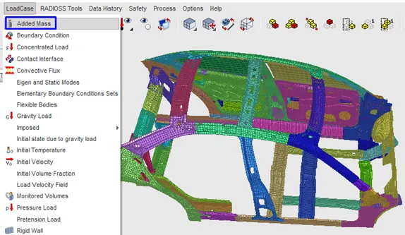
Added Mass > We will select Type 1 to distribute the mass symmetrically. Typ=1 (mass is distributed on each node of the selected group)
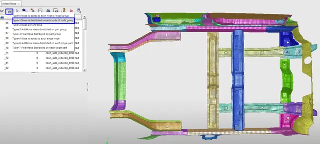
After adding the mass, we measure target mass as 700kg that is on the x-axis in the figure 12 below.
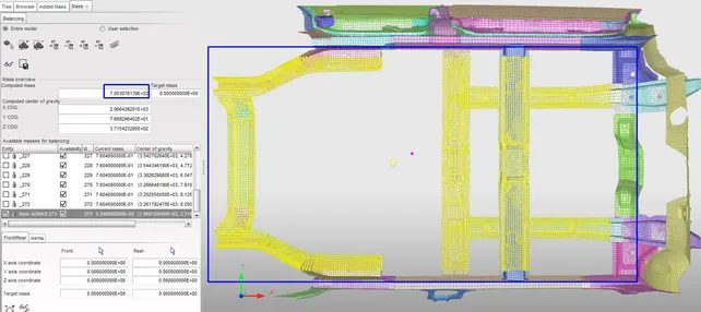
Figure 12
The model with added mass will be exported into the RADIOSS to import again into hypermesh.
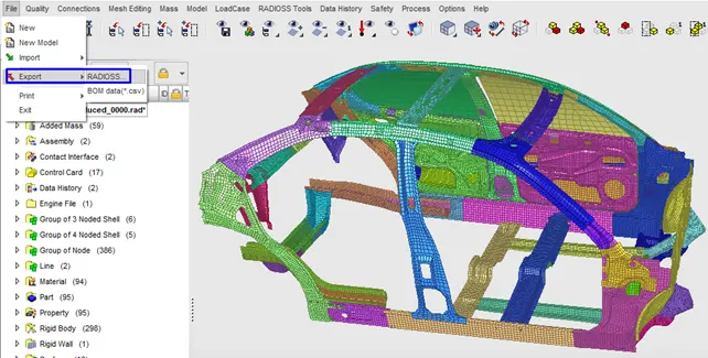
7) To set an Initial velocity 35 mph.
/INIVEL: defines initial velocity on a group of nodes.
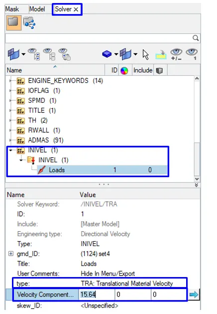
35 mph= 56.33 km/h= 15.64 m/s
We will create initial velocity (INIVEL).
Solver> Create> Boundary conditions> INIVEL
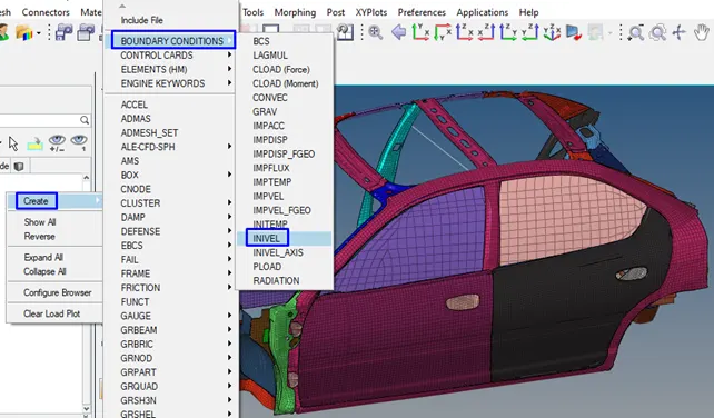
We will select Complete_Node_CAR for gmd_ID that is the group of nodes.
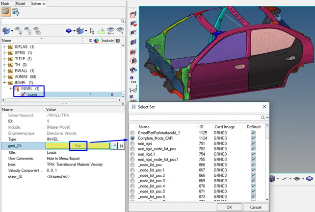
We will define the type of velocity as Translational and set the velocity (15.64 m/s) in translational Y Direction. (0,15.64,0)
Create Cross Sectional
We have to set cross sectional to take Output request.
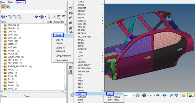
/SECT: Sections are used to output the force and moment of a cross section defined by a group of nodes and groups of elements.
To set cross sectional for two cross members
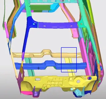
We will create section on the Solver and rename as cross member right/left.
We are selecting N1, N2, N3.
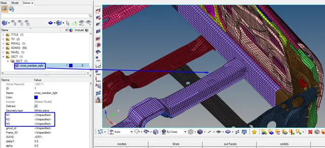
The first node (N1) always defines the origin of the local coordinate system. The direction from the first node (N1) to the second node (N2) defines the local axis. The third node (N3) lies in the plane of interest.
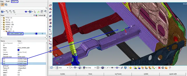
Cross member right: Cross sectional elements area will be selected
/GRSHEL> Card Image: GRSHEL: Describes the shell groups which are selected from other shell groups.
To select elements for grshel_id in the /sect/ of the cross member right/left, pillar etc, we have to create the shell group for each section where forces will be calculated through them.
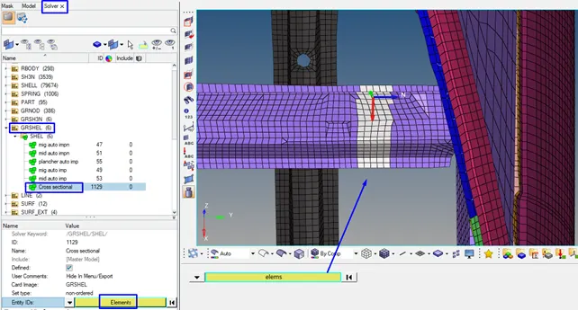
Frame for cross member right
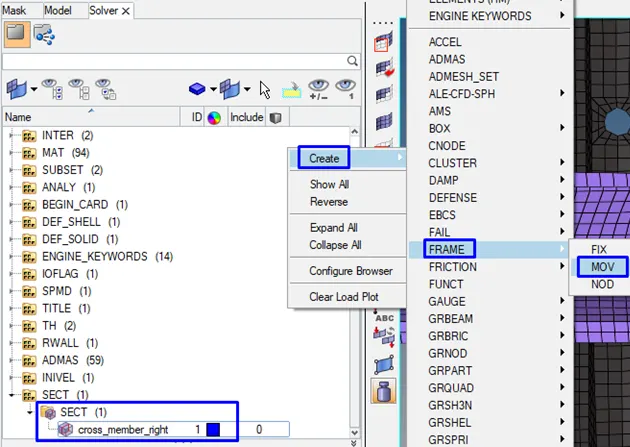
For each section, we will create frame to make local coordinates of the section.
Solver> create> FRAME> MOVE
/FRAME/MOV: Describes moving frames. Relative motion with respect to a reference frame.
For the frame, we will select same nodes that are origin node (N1), axis node (N2) and plane node (N3) as we have selected in /SECT/cross member right (N1, N2, N3).
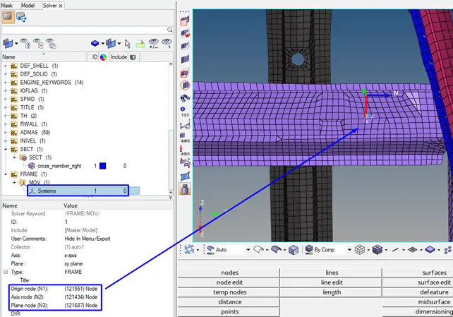
Frame ID: 1 and grshell_id: cross Sectional member right will be confirmed in the /SECT/cross member right. You can see the section plane that was created to output cross-sectional force.
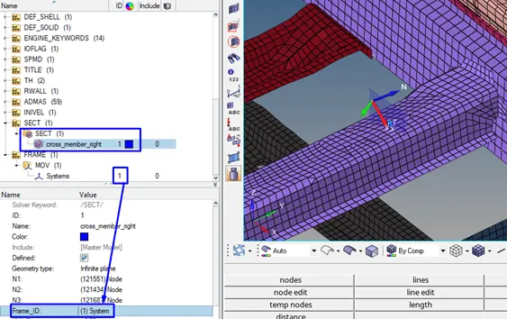
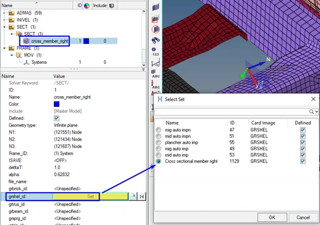
We have been created first cross member Right-Sectional. Other section will be selected in the same way.
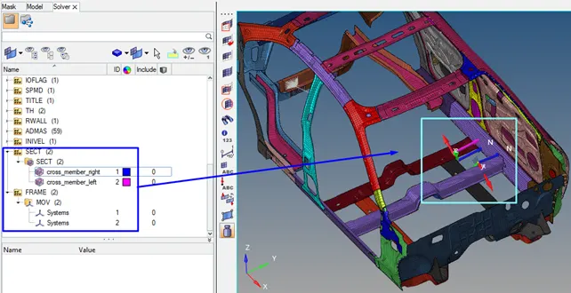
To create Spring
We will create three springs to measure intrusions at B pillar, hinge pillar and fuel tank region.

Intrusions at B pillar (left), hinge pillar (middle) and fuel tank (right) region. Nodes in the below figure.
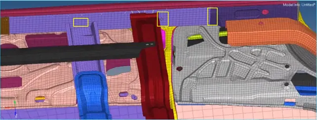
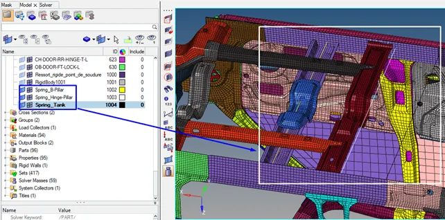
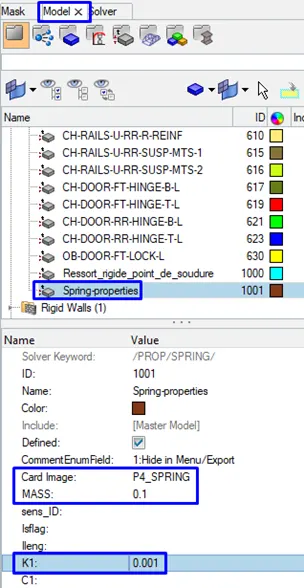
With this spring, we can check reduction of the length on the spring with respect of the Y in the Global Y. Only trick is here, the stiffness of the spring should be very small 0.0001 KN/mm. These Intrusions with respect to a frame of reference.
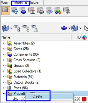
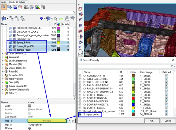
We will create a new property for spring on the Properties.
Output requests -TH (Time History)
1) Sectional force in the cross member
2) Intrusions at B pillar, hinge pillar and fuel tank region. Provide recommendation on what can help to reduce Fuel tank intrusions.
3)Peak velocity of inner node of the door
To create TH (Time History) for Cross member sections, Springs and RWALL
We will delete all TH that exists and create new.
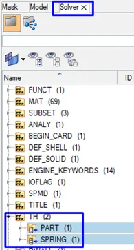
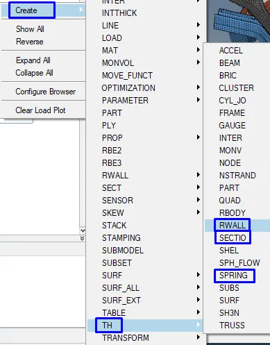
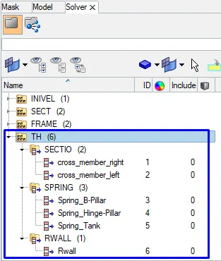
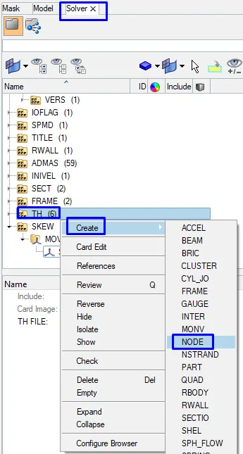
Create>> TH>> SPRING (3 springs>> Name: Spring_B-Pillar, Spring_Hinge-Pillar, Spring_Tank)
Create>> TH>> SECTIO (2 sections>> Name: cross_member_right and cross_member_left)
Create>> TH>> RWALL
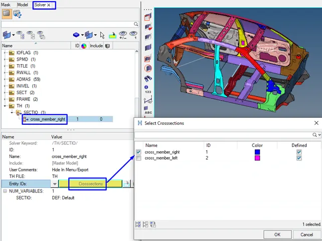
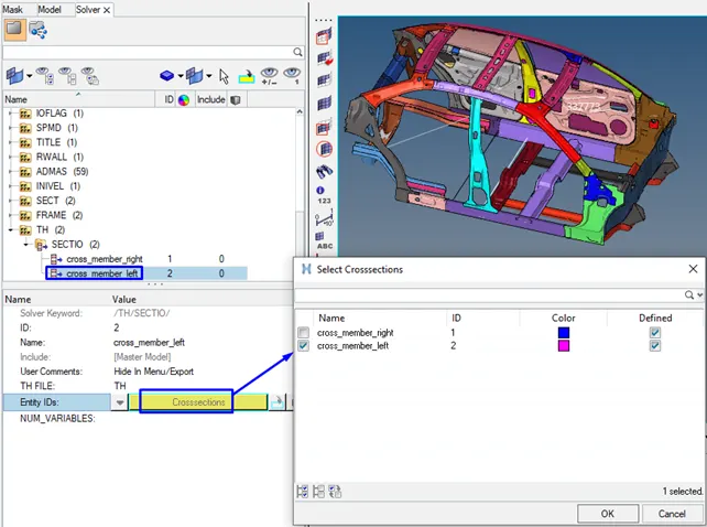
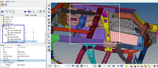
Other cross sections (springs, RWALL) in the below figure will be selected in the same way.
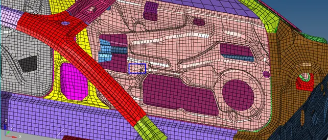
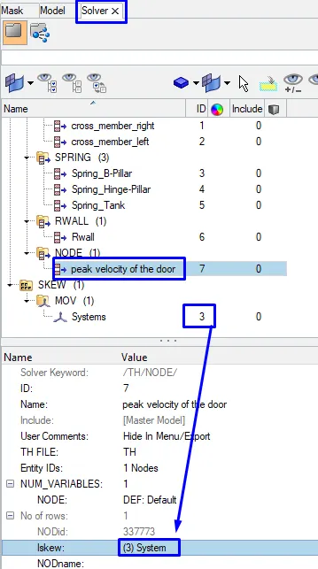
Peak velocity of inner node of the door (peak velocity for this particalar node 337773)
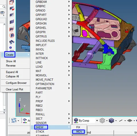
We will create Skew>>MOV at the inner node (337773) of the door on the solver to find peak velocity.
/SKEW/MOV: Describes a moving local coordinate system.
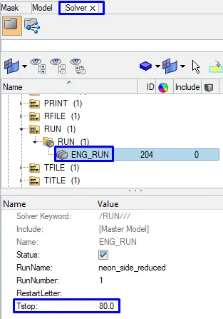
To set time-step: 0.5 to 0.1 microseconds and Run 80 ms
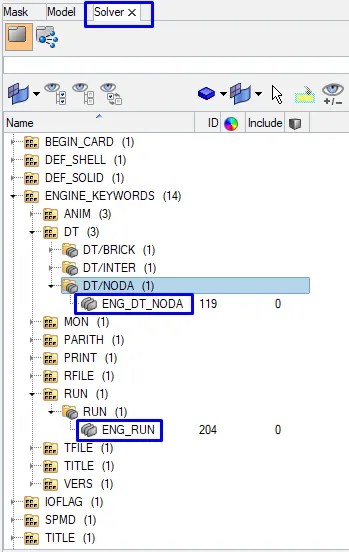
We can set time step and run time in two ways.
1) Model> Cards> ENG_ANIM_DT
ENG_DT_NODA
ENG_RUN
OR
2) Solver>> ENGINE_KEYWORDS>> ANIM>> ANIM/DT>> ENG_ANIM_DT
>> DT >> DT_NODA
>> RUN>> RUN>> ENG_RUN
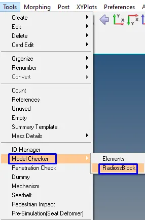
We will control RadiossBlock Whether it has got some error.
Tools>> Model Checker>> RadiossBlock
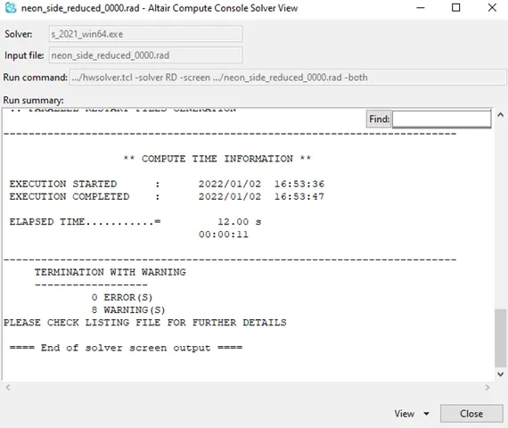
Output request (TH: Time History)
1) Sectional force in the cross member
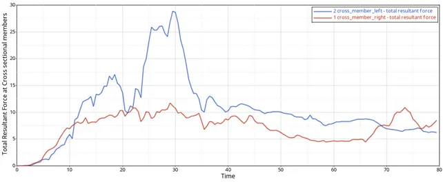
The maximum cross-sectional force at cross member left is 28KN at 29ms. For cross member right, the maximum cross-sectional force is 12 KN at 73ms.
2) Intrusions at B pillar, hinge pillar and fuel tank region. Provide recommendation on what can help to reduce Fuel tank intrusions
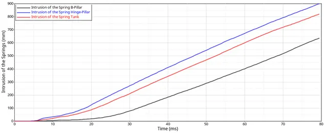
The maximum displacement of the springs is spring-Hinge Pillar with 900mm. There is no other component in the middle section of the car to absorbe the impact energy, therefore there is very huge deformation at these springs locations. We can add extra structure at the near of the tank to reduce fuel tank intrusions.
3) Peak velocity of inner node 337773 of the door
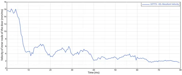
We can see from the Graph that the peak velocity of the node 337773 on the door is 16.1mm/ms at 4ms.
Check the Energy and Mass Error
After running the simulation, we will open neon_side_reduced_0001.out file with using notepad to control the energy error and mass error whether results would be acceptable.
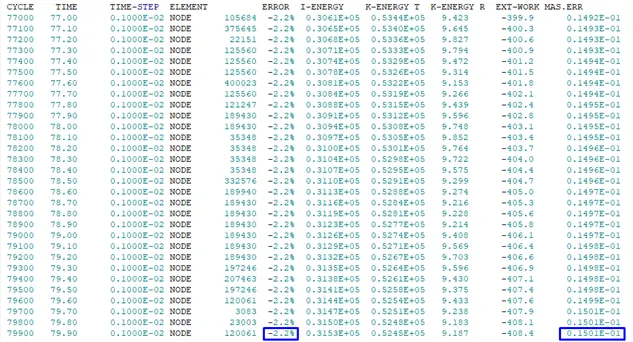
The energy error must be negative and decreasing. The error must be less than 15% at the end of the computation. The energy error is -2.2% and mass error is 0.1501E-01 at the end of the computation. The energy error is below the 15%. Therefore, the results are acceptable to plot energy graph.
Internal, Kinetic, total energy
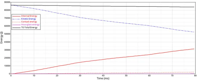
The car loses kinetic energy during the crash. At the same time, kinetic energy is converting into Internal energy that occurs the deformations in the BIW structure. The total energy is almost constant 85000J. We can see that the hourglass energy is small enough to be neglected therefore there is some decrease in total energy.
Results
Side pole crash simulation was carried out under the given requirements. Energy, Member Cross sectional forces, Intrusions (at the B pillar, hinge pillar and fuel tank region) and peak velocity of the inner particular node of the door as the output request were plotted and discussed. To reduce deformation of the near of the tank, an extra structure can be added at the near of the tank to increase the stiffness of the BIW.