Assignment 2-RADIOSS Engine File Editing & 3D Meshing Challenge
Assignment 2-RADIOSS Engine File Editing & 3D Meshing Challenge
Objective:
- To check the material properties of the rail component and calculate the speed of sound in steel rail.
- To calculate the time takes for a shock wave to travel from one end of the rail to the other. The length of the rail is about 1000 mm.
- To set the frequency of animation output to a time that will give 20 animation steps (/ANIM/DT)
- To edit the engine file so that the stress wave can be monitored, moving from one end of the rail to the other during impact. This will require a termination time equal to the time it takes for the sound to travel the length of the rail (set on/RUN card)
- 3D meshing tetra mesh and hex mesh with given quality parameters which are target tet size=5mm, hex size=10mm and tet collapse=0.15.
1. To check the material properties of the rail component and calculate the speed of sound in steel rail.
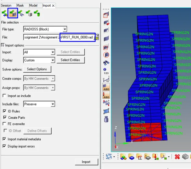
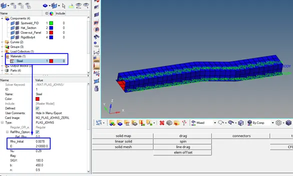
We will import the starter file which is given as FIRST_RUN_0000.rad in order to check the material properties.
The speed of sound in steel rail
c : speed of sound
E : Modules=210000 Mpa=210000 N/mm^2
1 N= 1 kgm/s^2
ρ : density= 0.0078 gr/mm^3

2. To calculate the time takes for a shock wave to travel from one end of the rail to the other. The length of the rail is about 1000 mm=1m.
Time for sound to travel length of rail:

3. Set the frequency of animation output to a time that will give 20 animation steps(/ANIM/DT)

4.Edit the engine file so that the stress wave can be monitored, moving from one end of the rail to the other during impact -this will require a termination time equal to the time it takes for the sound to travel the length of the rail (set on/RUN card)
We will open the Engine file (FIRST_RUN_0001) in Notepad in the figure below. We will see termination time in 3. Row and animation frequency in 11. Row. They have to be edited with new values which are calculated in the previous section.
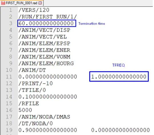
Figure 1: Engine file (FIRST_RUN_0001)
After editing engine file with new values, the engine file is shown in the figure below.
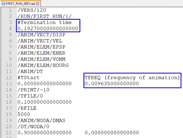
Figure 2: after editing engine file
5. 3D meshing tetra mesh and hex mesh with given quality parameters which are target tet size=5mm, hex size=10mm and tet collapse=0.15.
3D Meshing of Arm Bracket with Hypermesh
Import the model using standard toolbar> Import> Import Geometry
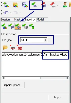
Figure 3: To import Model
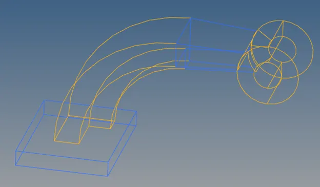
Figure 4: after importing the model
We will check surface defects on the model. But there are no missing surfaces and free surfaces on the model (Fig2).
Arm_Bracket_01. step consists of 5 components which are model, model 2, model 3, model 4, model 5 in the model browser.
we will create 2D mesh (quads only) on the surface of the “model” component.
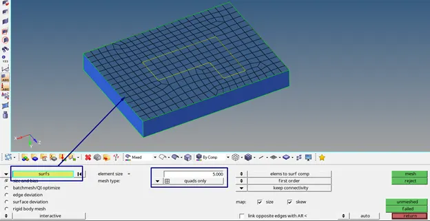
We will convert all quads element on the surface of “model” to 3D hexa elements. We will use solid map on the 3D Panel for it.

With this option, 2D elements are extruded to 3D elements along line with density 5.
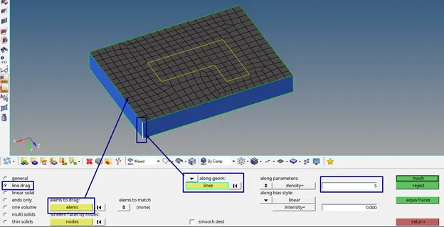
If we carefully observe the model 2, we can spin or drag the 2D elements of model (Figure 4) which are shared with model 2.
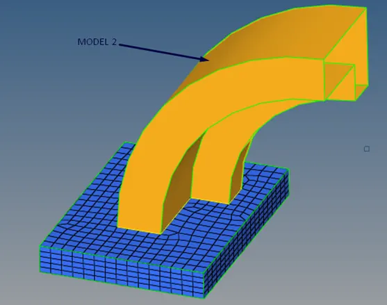
Figure 5: model 2
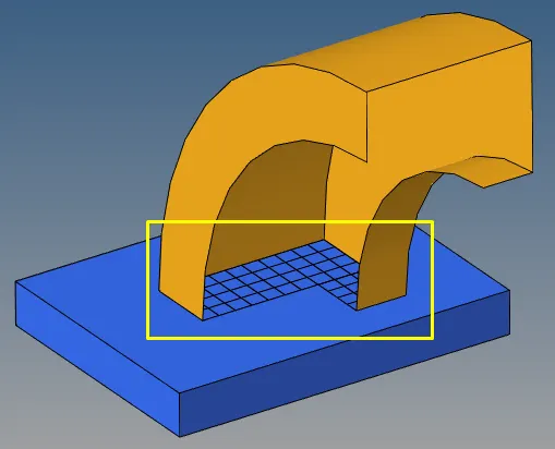
Figure 6: shared elements with model 2
In order to spin these elements, we have to measure the angle through which elements are rotated or spinned. Firstly, we will create a node on the arc center with Nodes on the Geom Panel.
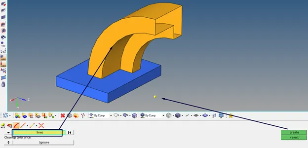
Figure 7: a node on the center
To measure the angle between three nodes, we will use Geom Panel> Distance. We can see, total angle is 89.387 degree.
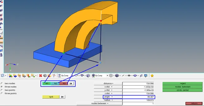
After measure the angle, we will spin the element 89.387 degree about the angle center. 3D Panel> spin

B is the point about which axis we will rotate the 2D elements.
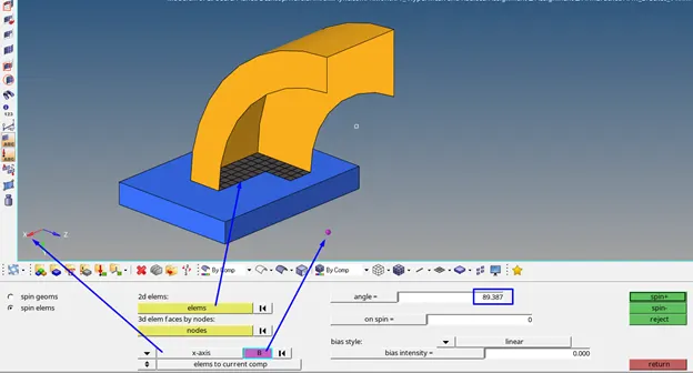
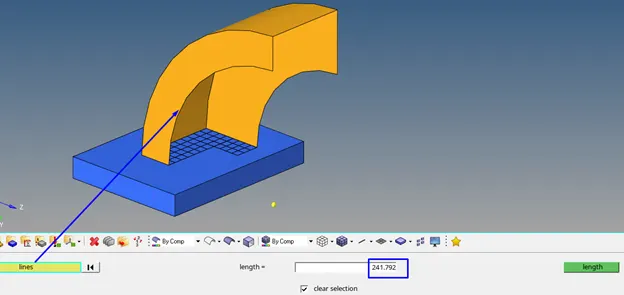
On spin is how many number of elements we want while we are spinning the elements along the arc. We will maintain our element size to be 10. So first we will have to measure the length of this arc. To measure the legth, we will go to Geom Panel> length. We see the total length of the arc 241.792mm. So it is divided by ten, it gives approximately 24 number of elements.
On the first, we will put 25 number of elements. If we spin the elements spin -, it will get rotated in clockwise direction and 3D elements have been created (Figure 8)
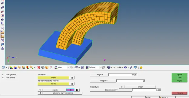
Figure 8: 3D elements created by spin option
But we have to check whether the elements are completely full filling the geometry or not. We can see the gap between the geometry and mesh structure.
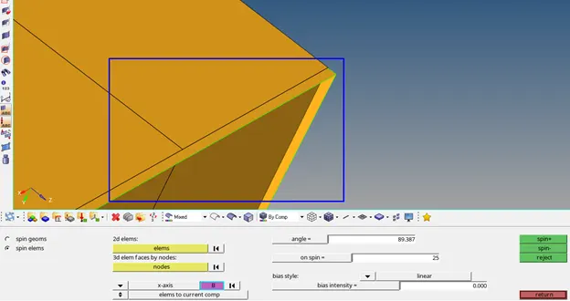
Figure 9: the gap between the geometry and mesh
Instead of using spin option, we will use solid map> line drag from 3D panel.

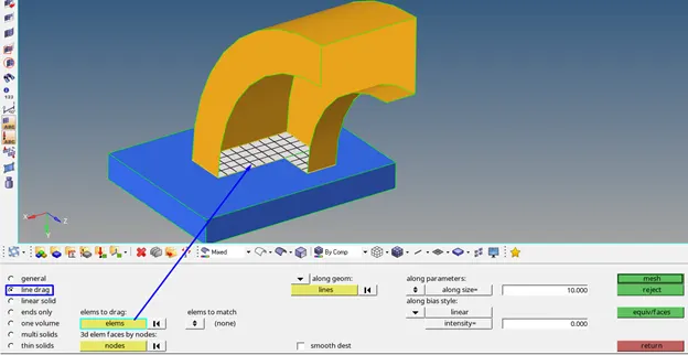
We will select the multiple lines so that 2D elements will be able to follow all these lines. We will maintain the element size of 10.
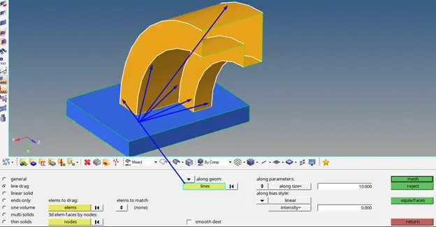
Figure 10: selecting of the multiple lines
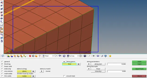
If we will zoom in it and we will see that the mesh has been very properly followed and we will be able to see properly end of the mesh has been followed. This is the actual way to prepare the geometry and to measure it accordingly. We have to check whether the elements that are actually representing the geometry or not.
We will mesh model 4.
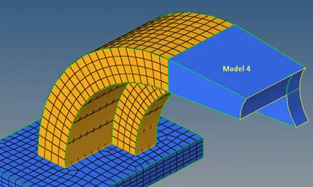
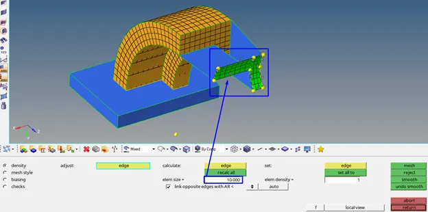
We will use linear solid option from 3D panel.

To perform linear solid to obtain 3D mesh, we have to create 2D elements on the model 3.
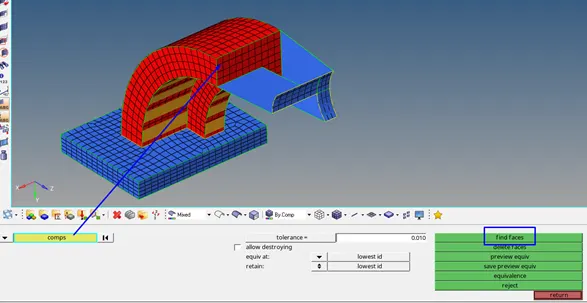
After finding of the faces, we will use linear solid option. (Figure 11)
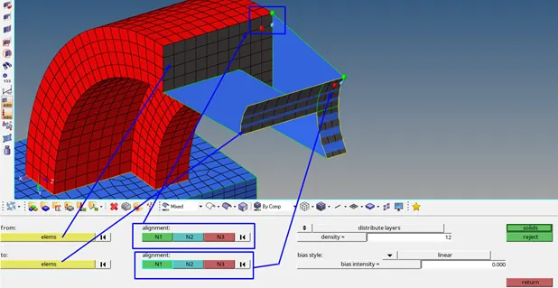
Figure 11: application of linear solid option
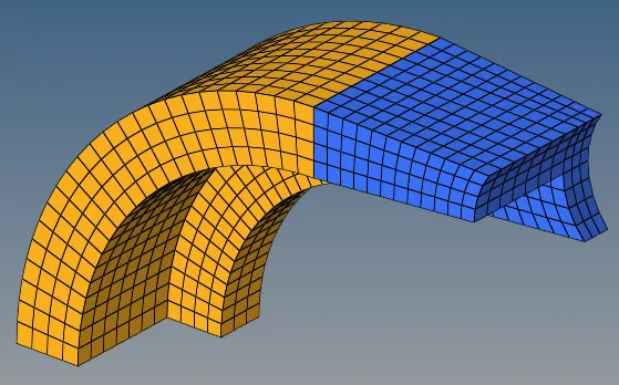
Figure 12: result of the linear solid
We will mesh model 5.
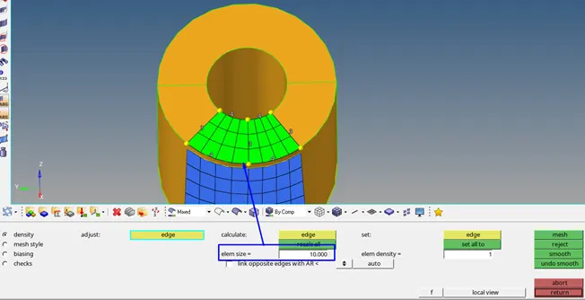
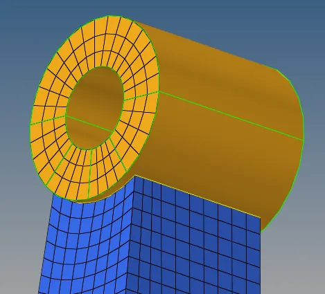
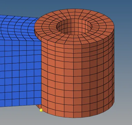
After meshing of the component surface, we will perform solid map> general.
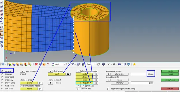
Figure 13: application of the solid map
Tetramesh-3D Meshing of housing model with Hypermesh
After importing of “Housing_01. step” in hypermesh, we will check the model if it has got surface defects to clean up the geometry. There are not any defects on the geometry.
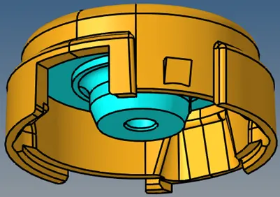
Figure 14: housing model
Firstly, we will mesh the surface of “model 2” with mesh type 2D trias and 5mm target element size.
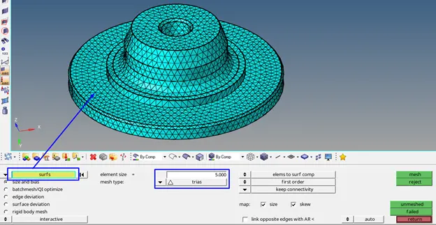
Figure 15: model 2
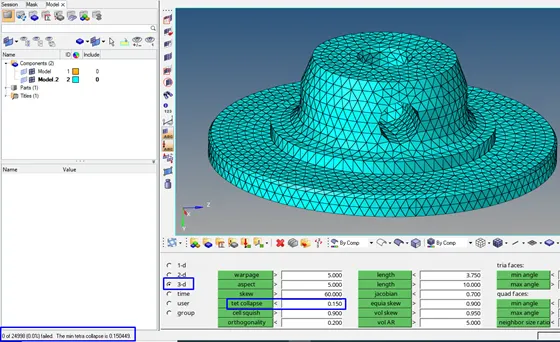
We use tetramesh on the 3D panel in order to convert 2D trias elements to 3D tetramesh. Before meshing, we will set mesh quality criteria as tet collapse< 0.15.
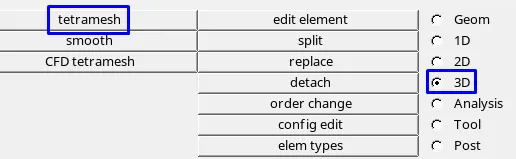

We will convert 2D trias elements to tetra mesh
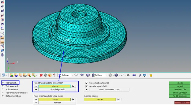
3D mesh will be created as shown on the figure below. We can check it with mask option If 3D tetramesh in the model is created.

Figure 16: 3D tetramesh is correctly created
We will see the result of tet collapse criteria on the figure below. We have zero elements which are failed.
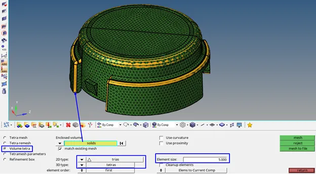
For the next model, we will use volume tetra mesh method which creates 3D tetras elements in the enclosed volume of the component. We will maintain element size as 5mm.
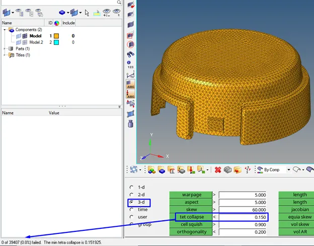
We will check for tet collapse criteria. We have zero elements which are failed.
Conclusion
The material properties of the rail component are checked from file FIRST_RUN_0000.rad. The speed of sound, time for sound to travel length of rail in steel rail and frequency of animation are correctly calculated. Then the engine file is edited with these calculated values. At the end of this work, the two components (arm bracket and housing) are meshed using 3D elements which are tetra and hexa elements.