Assignment 7
Objective
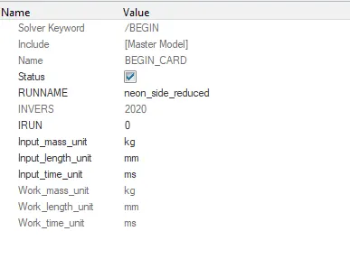
1) To follow either of the given unit systems .
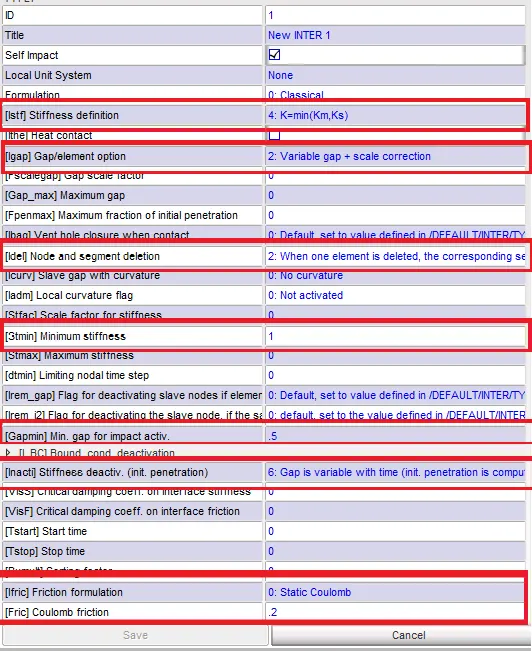
2) To create appropriate interface with friction 0.2 and recommended parameters .
3) To check for initial penetrations and intersections .
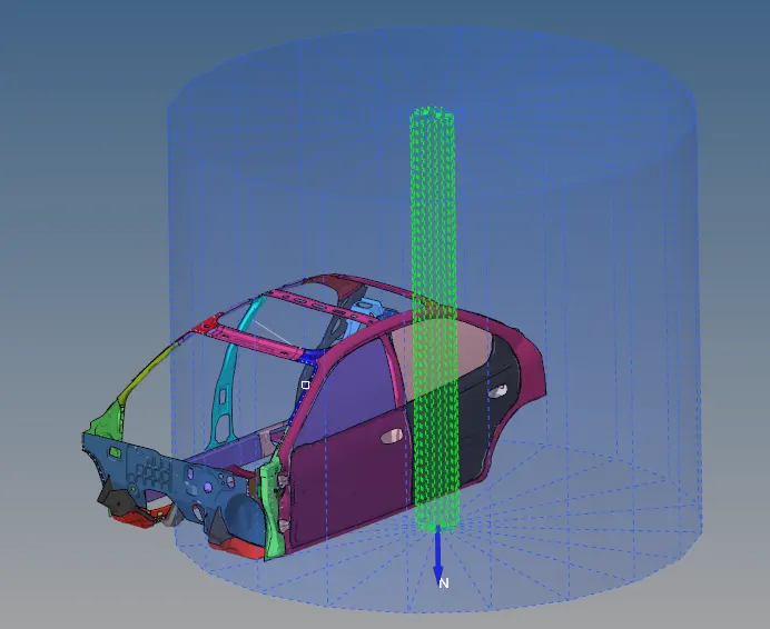
4) To create a rigid wall with friction 0.1 .
5) To add mass to make total weight 700 kg and position CG at required place .
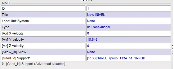
6) To assign initial velocity og 15.646 mm/ms.
7) To use model checker to ensure good quality .
8) To assign a timestep value between 0.5 to 0.1 microseconds .
9) To run the simulation for 80ms .
Output request
a) Sectional force in cross members .
b) intrusion at B pillar , hinge pillar , fuel tank region . Provide recommendation to reduce fuel tank intrusions .
c) Peak velocity of inner door node .
Procedure
1) To check the unit system , begin card was used to ensure that the required unit systems were followed . The crash was opened in kN,kg,mm,ms format and the model was imported .
2) To create interface , contact interfaces option was selected from load cases option .
Recommended values were entered after selecting respective master and slave nodes .
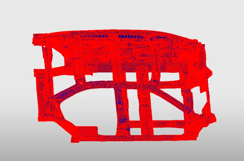
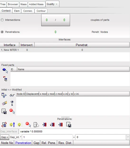
3) To check for initial penetrations and intersections , check all intersections option was chosen from quality option .
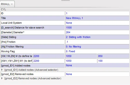
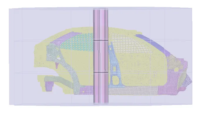
4) To create a new rigid wall , rigid wall option from load cases was selected .
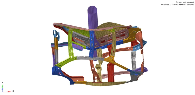
Cylindrical option was selected and required values were entered .
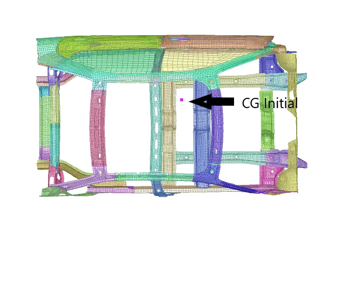
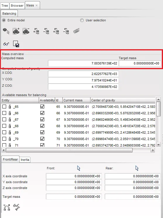
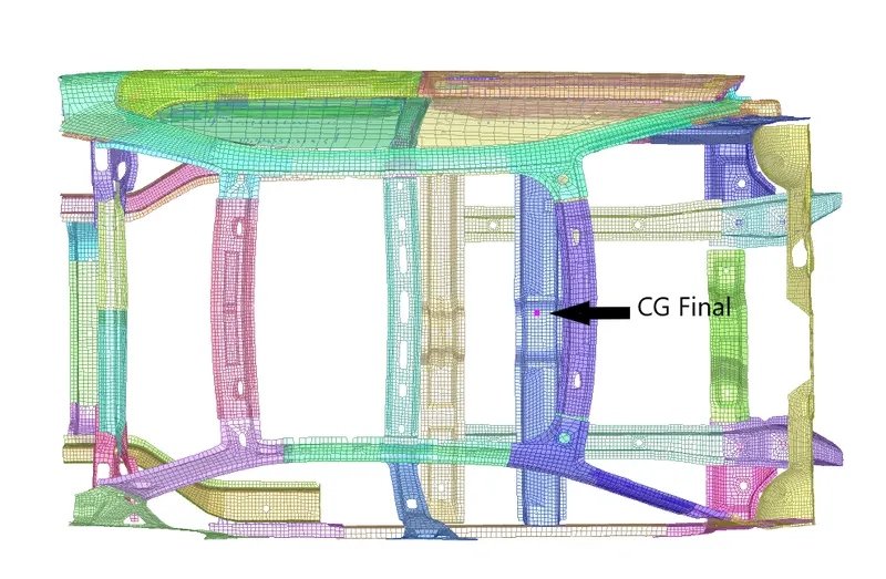
5) To add mass and position CG , balancing option from mass tab was selected to locate initial CG . Then added mass option from load cases tab were used to make total mass 700 kg.
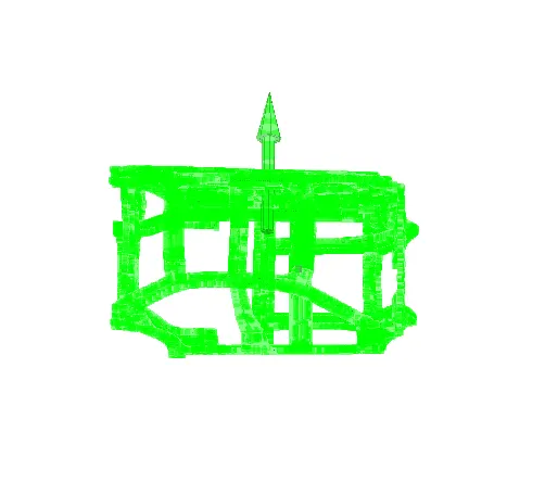
6) To assign initial velocity to nodes , initial velocity from load cases tab was chosen and values were entered .
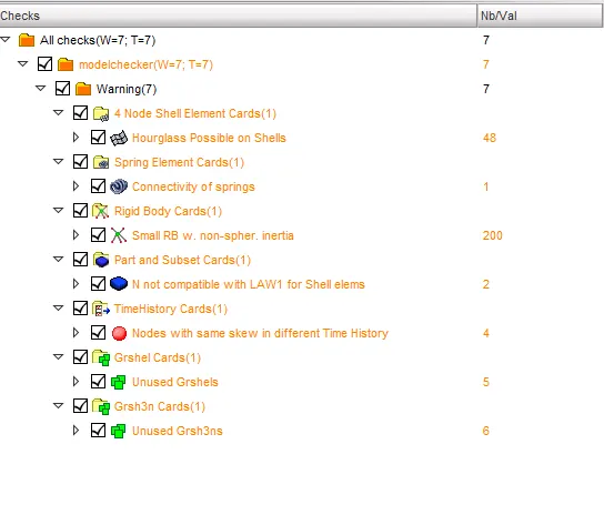
7) Model checker was run from quality option and no errors were found .
8) The solver deck was imported to hypermesh .
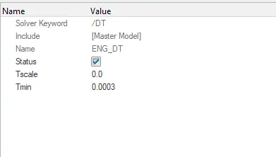
ENG_DT card was created and Tmin value was entered as 0.0003
9)
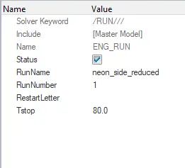
To run simulation for 80ms , Tstop in ENG_RUN card was changed to 80ms .
Output Requests
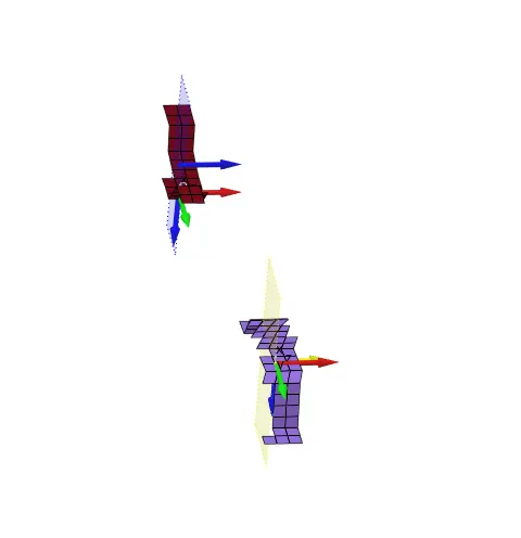
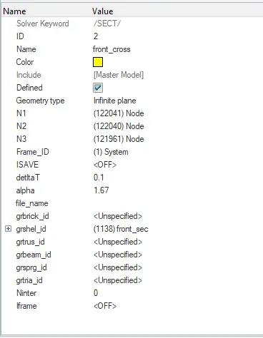
a) To plot sectional forces at cross members , 2 moving frames were created using solver option at 2 cross members and respective elements were selected .
The TH_SECTIO option was used to get outputm of assigned frame and elements respectively .
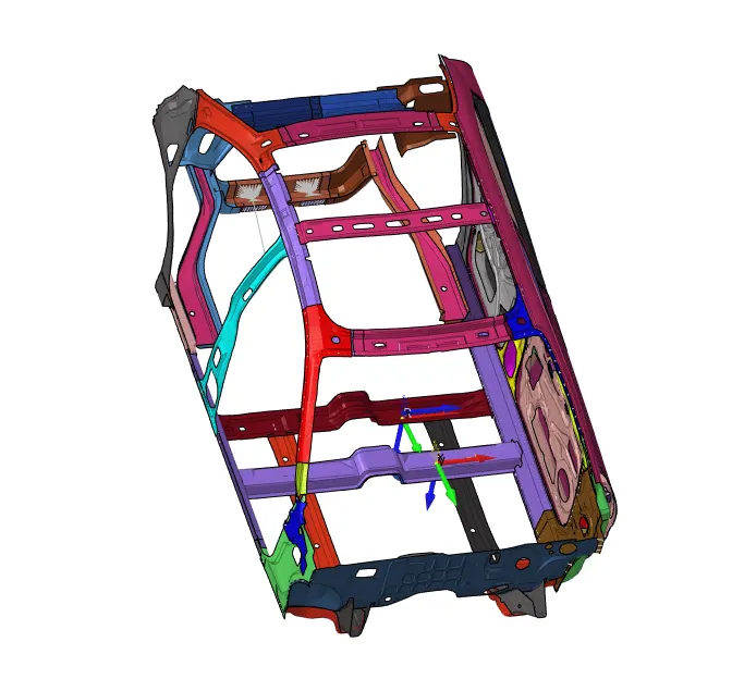
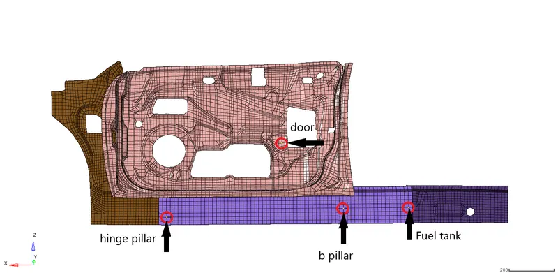
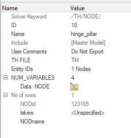
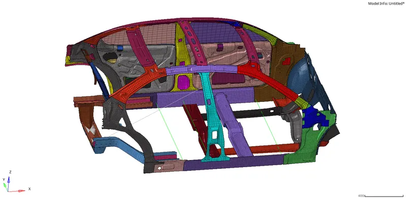
b) To find intrusion of the fuel tank , b_pillar and hinge_pillar into the passenger cabin , 3 nodes were identified with ID 123362 , 123345 and 123165 respectively .
TH_SPRING was created using solver option for each of these nodes to measure intrusion into the passenger cabin.
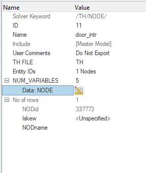
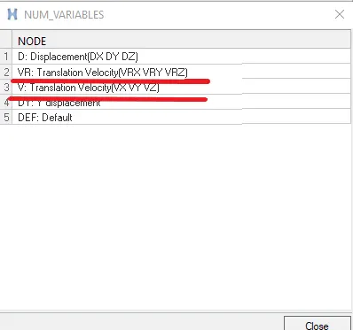
c) To plot peak velocity of node of the inner door component , in TH_NODE option , velocity was also requested .
Results
a) Sectional forces at cross members
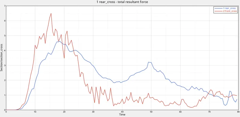
Here we can observe that the front cross member experiences a peak force value of about 6.5kN at around 15ms and rear cross member experiences a peak value of 4.5kn at around 18ms . Once the force value reaches the peak ,it gradually reduces by time . This is explained by the additional support given at the center of the front cross member , it is able to sustain such higher forces and lets the rear cross member to deform at a delayed time period .
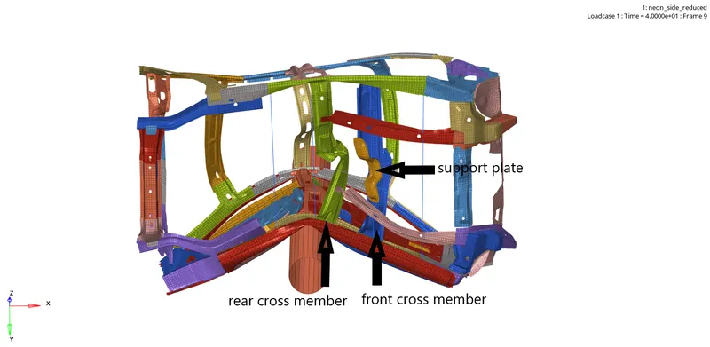
b) Intrusions at hinge pillar , fuel tank and b pillar region .
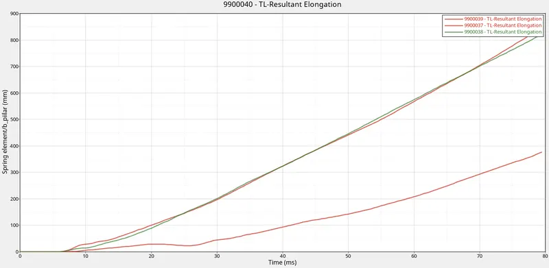
Here the element ID corresponds to following 9900037 - B pillar region
9900038 - Fuel Tank region
9900039 - Hinge Pillar region
We can observe that the intrusion of b pillar region is maximum at approximately 850 mm and that of fuel tank region is about 820mm and hinge pillar region is about 380mm .
Inorder to reduce the intrusion at fuel tank region , an additional cross memeber can be added or reinforcement plates can be added in that area .
c) Peak velocity of node ID 337773
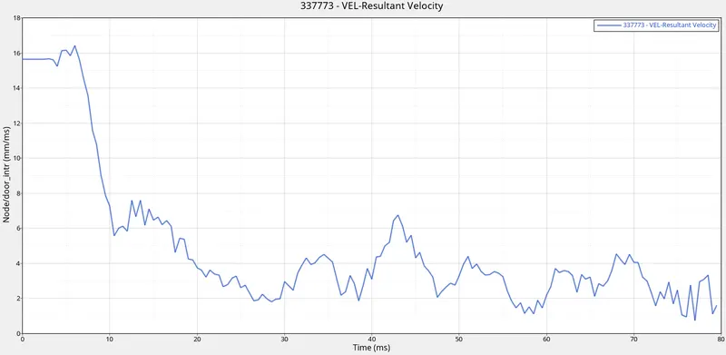
Here we can observe that the peak velocity is about 16.3mm/ms around 6ms and reduces gradually over time . This is due to the impact with the rigid wall and ineria that peak valocity is reached right after the impact with rigid wall .
Energy graphs
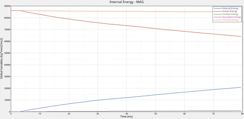
Here we can observe that kinetic energy is converted into internal energy as kinetic energy decreases and internal energy increases . We can observe that the conversion is kind of small because of the reduced sectional area of the rigid wall . The contact energy is very small because of low interface forces , hence the reduction in total energy is also very small . hourglass energy is very small or minimal because of QEPH element formulation used here .
Conclusion
We can conclude that the front cross member is the primary force absorbing component . The passenger cabin intrusion happens only after the front cross member has deformed . Fuel tank region must be provided with additional support inorder to reduce intrusion in that region .