Assignment 6-Frontal Crash Simulation Challenge
FRONTAL CRASH SIMULATION OF DODGE NEON CARS
PROJECT 1- Crashworthiness analysis Using Hypermesh, Radioss and HyperCrash
Aim: To perform a frontal crash simulation analysis Using Hypermesh and Hypercrash to notice the difference in their Energy impacts.
Objectives: For the requested outputs there are certain objectives that are:
- To perform the crash on the frontal section of car and to check where stresses are acting on it.
- To check the unit systems and change if necessary.
- Create an interface of Type7 with the friction value of 0.2 and other recomended parameters.
- Making sure there no penetrations in rummimg the simulation.
- Creating a rigidwall with friction 0.1.
- Comparing the model weight with the full scale 300k nodes model and use added masses to reach the target weight of 700Kg while getting Centre Of Gravity about required range.
- Give an Initial Velocity of 35mph.
- Use a model checker to Ensure Good quality .
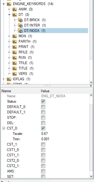
- Providing a Timestep: 0.5 microseconds.
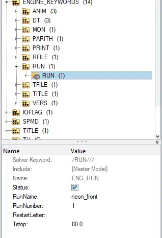
- Give run time as 80ms.
Output Requests:
- Sectional Force In the rails at location of indicated node 174247.
- Axial force recived on the rails from bumper.
- Shotgun cross sectional force.
- A Pillar cross sectional forces.
- Acceleration curve recieved on the accelerometer at base of B pillar .
- Intrusions on the dash wall 66695,66244.
Brief:
A crash test is a virtual reconstruction that replicates the same forces and speeds that would occur if the vehicle was to be involved in actual crash.In this type of testing, since nothing is physically impacting the Body-in-white(BIW). No physical deformation or damage occurs to the body's structure, allowing multiple crashworthiness tests to be conducted in the successsion. This type of simulation is an integral part of the design process and can help save both time and money.
For this project, case setup and simulation are to be done in Hypercrash, where as Hyperview and Hypergraph2D will be used for post-processing. Hypergraph will be used to plot energies, von misses stresses, plastic strains, accleration curves, and Hyperview will be used to view the simulation.
In the part of simulation we will be creating a rigid wall, providing a initial velocity of 35mph, manipulation of masses to ensure the total weight of 700kgs with maintaning centre of gravity in specified region.
WHAT IS A CRASH TEST?
A crash test is a form of destructive testing usually performed in order to ensure safe design standards in crashworthiness and crash compatiblity for various models of transportation or related systems and components.
Various crash tests:
- Frontal Impact test: In this test fully front structure of the vehicle collides with another object like another vehicle, rigid wall etc, at a given speed.
- Offset Test: In this test a part of front portion of the vehicle strikes on some barrier a particular speed.
- Side Impact Test: In this test some time the vehicle is in static condition or in dynamic and another vehicle or an objec collide additional relative speed.
- Roll-Over test: In this test a vehicle is in roll over condition having a certain angle with support itself a dynamic impact.
- Road side hardware: It is performed to test the crash barriers, and crash cushions will protect vehicle occupants from road side hazards.
- Old vs New: In this impact, an impact is done between an old car against a new car and big car vs small car to compare the advancements in crashworthiness.
Crash tests are conducted under rigorous scientific and safety standards. Each Crash test is very expensive so the maximum amount of data must be extracted from each test. Usually, this requires the use of high-speed data acquistion, at least one tri-axial accelerometer and a crash test dummy, but often includes more. A crash test is much important which helps in minimizing the losses such as deaths, injuries, and property damages from the vehicle crashes on the roads.
In this project, we must perform a frontal crash of the vehicle. Frontal impacts are the impacts undertaken against the soild barrier. Frontal impacts are the impacts undertaken against the solid barrier with precise speed. The test requires the front portion of the vehicle to impact the barrier.
In the New car assessment program(NCAP), passenger vehicles are crashed at 35mph into a rigid barrier that covers the full width of the vehicle. The institute runs offset frontal tests instead of full-width frontal tests. In an offset crash only one side of a vehicle front end, not the full width, hits the barrier.
How crash testing works?
A crash test is destructive testing usually performed in order to ensure safe design standards in crashworthiness and crash compatibilty for various modes of transportation related systems and components.
Crash test dummies have been the subject of public service announcements, cartoons, parodies, even the name of a band. Real crash test dummies, however, are true life-savers as an integral part of automotive crash tests. Even thought cars get a little safer each year, and fatality rates are declinig, car crashes are still one of the leading causes of death and injury in the United States.
One of the reasons cars have been getting safer is because of a well-established testing program.
The dummies contain three type of instrumentation:
- Accelerometers: These devices measure the accelration in aparticular direction. This data can be used to determine the probabilty of injury. Acceleration is the rate at which speed changes. The crash test dummy has acceleromters all over it. Inside the dummy head, there is an acceleromter that measures the accleration in all the three directions(fore-aft, up-down, left-right). There are also acceleromters in the chest, plevis, legs, feet and other parts of the body.
- Load sensors: Inside the dummy are load sensors that measure the amount of force on different body parts during a crash.
- Movement sensors: These sensors are used in the dummy's chest. They measure how much the chest delfects during a crash.
Requirements in Crashworthiness:
The vehicle structure should be sufficiently stiff in bending and torsion for proper ride and handling. It should minimize high-frequency fore aft vibrations that give rise to harshness. In addition, the structure should yield a deceleration pulse that satisfies the following requirements for a range of occupants sizes, ages and crash speeds for both genders: Deformable, yet stiffness, front structure with crumble zones to absorb the crash kinetic energy resulting from frontal collisions by plastic deformation and prevent intrusion into the occupant compartment, especially, in case of offset crashes and collisions with narrow objects such as trees.
Procedure:
- Check for UNIT SYSTEM.
- Importing the model in Hypercrash.
- Check for pentrations and intersection.
- Add masses to reach a target weight of 700kg.
- Export changes file and import in HYPERMESH.
- Create a interface contact between component and bumper.
- Create a rigidwall
- Add velocity to the nodes.
- Creating a cross section.
- Creating acceleration nodes.
- Create springs to check deflection.
- Assign property to springs
- Create TH for section forces, intrusion springs, inreface contacts.
- Create crads.
- Model checker.
Unit system used for analysis is "kg mm ms".
Importing the model:
- For importing the model go to file>import>solverdeck>select file.
- Import the 0000.rad file using solver deck as shown in below image.
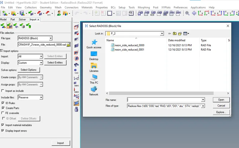
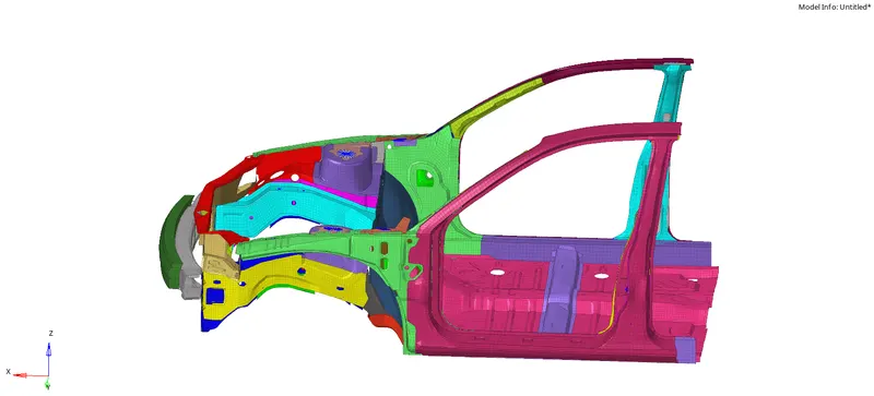
Imported model Image:
CHECKING FOR UNIT SYSTEM:
For checking unit system we have two files
- Neon_front_0000.rad known as starter file which has information in it like:
- Nodes
- Load conditions
- Velocity
- Boundary Conditions
- Has ASCII standard file
- And it always in 0000.rad format.
- Neon_front_0001.rad file known as engine input file. And it stores information such as
- Simulation Run_time
- Simulation Speed Control Parametres, such as No of Animation Files, No of Time History File, Size of the history file and animation frequency, etc.
- Has ASCII standard file.
- We can also manipulate the engine file directly through the control cards.
- It always ends with 0001.rad format.
Images for Starer and Engine file in NOtepad format.
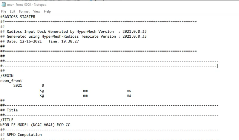
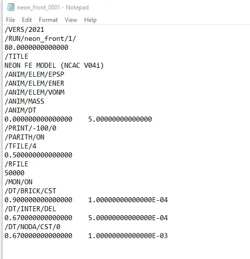
- So here the unit system is in 'kg mm ms' System only.
CHECKING FOR PENETRATIONS AND INTERSECTIONS:
- Penetrations is defines as the overlap of the material thickness of shell elements, where as intersection is defines as elements that pass completely through one another. All models and especially impact models should be checked for penetrations and intersections and they should be De-penetrated to ensure the integrety of the model. Pnetrations adversely affect results and should be removed.
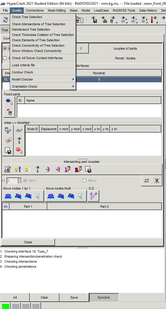
- To check penetration and intersection: Import the 0000.rad file in Hypercrash and Go to Quality>check all solver contact interfaces>select parts> click on check penetration.
- Refer below images for checking Intersections and Penetrations
Compare the model weight with full-scale 300k nodes model and use added masses to reach a target weight of 700kgs while maintaining the CoG in specified region.
- A Vehicles centre of gravity or CG is the theoritical point where the sum of all masses of each of ots individual components effectively acts. Carrying weight up-high such as panoramic sunroof will paise a vehicle CG while placing heavy subsystems low in a vehcle, such as battery pack, will work to lower it.Lower is better from a handling standpoint, as it reduces weight transfer during cornering and braking.
MASS ADDITION AND POSITIONING OF COG:
- Mass balancing: In order to maintain the CoG of a car, we must add mass for the given components, In the given model here are so many parts are missing because of the node limit in the student version.
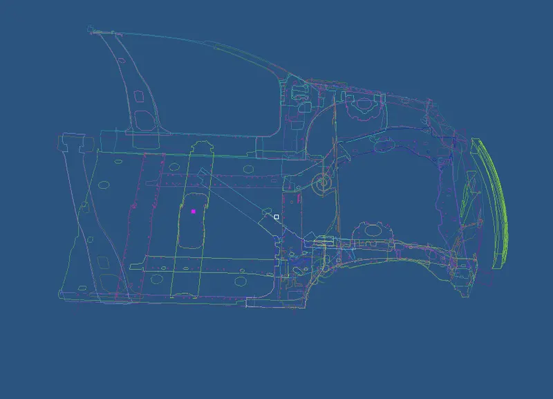
- To check the CoG, Go to menu>mass.Balancing>Show CoG point.
Images for Viewing CoG point.
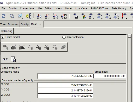
- By first image we can see that Mass of the body is around 750.2 Kgs which meets the target.
- For adding the masses manually select Loadcase>Added Mass>Select nodes.
We must add the masses in sucha way that the centre of gravity is exactly in the middle of cross Beam to simulate the real world model. It is only bothered about the position CoG and not the height(Z-axis). We generally use Type1 mass, where mass is distributed on each node of the selection process.
- Refer below images for adding of masses and their parameters.
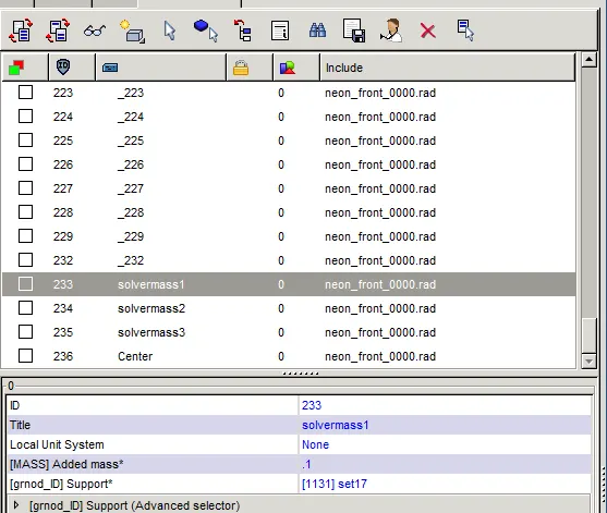
- The added mass tab is used for scale factor for mass.
- Grnod_ID referred as support is for set of selected nodes for assigning mass to them.
- Generally, for assigning mass right click on 'grnod_ID'>select in graphics>select nodes.
- And click on save to assigning masses.
EXPORTING HYPERCRASH FILE:
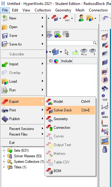
- For exporting the recommended parameters model after applied, go to file>Export>SolverDeck>rename file with 0000.rad file format.
Note: However saving in HyperCrash file the same can be opened for Hypermesh in Radioss Profile. Saving in Hypermesh has low error rate while in UNIT system conversion.
- Refer below image for Exporting the file in HyperMesh.
Creating Type7 Contact interface:
In this case, the TYPE7 contact interface is defined. Interface TYPE7 is a multi-usage impact interface, modelling contact between a master surface anda group of slave nodes. It is also possible to consider heat transfer and heat friction.
All limitations that were encountered with interfaces TYPE3,TYPE4 AND TYPE5 are solved with this interface
- A node can at the same time be a slave and a master node.
- Each slave node can impact each master segment; except if it is connected to this segment.
- AA node can impact m,ore than one segment.
- A node can impact on the two sides, on the edges and on the corners of each segment.
- It is a fast search algorithm without limitations.
The main limitations of this interface are:
- Time step is reduced in case of high impact speed or contacts with a small gap.
- It does not work properly if used with a rigid body at high impact spped or a rigid body with a small gap.
It does not solve edge to edge contact to solve this, /INTER/TYPE11 should be used along TYPE7).
- At the beginning there was a 6 interfaces of type 7 used to the BIW structure but there was no proper connection present in the whole model so for the betterment of the model we have to delete those interfaces present and have to create a new interface the whole model for proper connection.
TYPE7 : NODE TO SURFACE
This interface simulates the most general type of contacts and impacts. TYPE7 interface has the following properties:
- Impacts occur between master surface and a set of slave nodes, like the TYPE5 interface.
- A node can impact one or more master segments.
- A node can impact on either side of a master surface.
- Each slave nodes can imoact each master segment except if it is connected to this segment.
- A node can belong to a master surface and as et of alave nodes.
- A node can impact the edge and corners of a master segment. None of the previous interfaces allow this.
Recommended Properties:
- We need to give in the slave nodes and the master segment. Since we are defining a self-impact in the model, the slave and master segments fro this contact will be the entire given model. So we then select all the nodes for both segments respectively as shown below.
- Also, delete all the other compnonents under Groups as they are not assigned to any part in the model.
Image of TYPE7 properties:
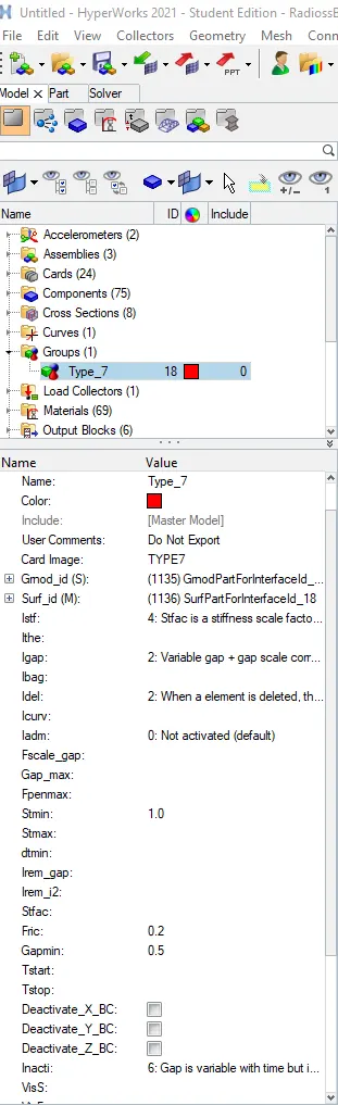
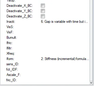
- Properties are assigned to TYPE7 with recommended paramters.
- To ensure the selected components make sure to review the select parts.
CREATING A RIGID WALL:
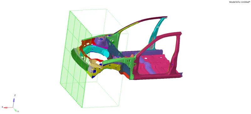
- A Rigid wall is a nodal constraint applied to a set of slave nodes in order to avoid the node penetration to the wall. If contact is detected, then the slave node acceleration and velocity are modified. Mainly to constrain the movement of a moving body after imoact, we wll be using a plane wall. An infinite plane wall is a plane that extends to infinty. And it is defined in two points.
- Rigid wall entities provide a method for treating a contact between a rigid surface and nodal points of a deformable body. In the radioss user profiles, rigid wall can be created in the model and solver browsers as well.
- To create an RWALL: Go to solver browser>create>RWALL>PLANE.
- We need a refernce node to create an RWALL so for that we are creating a temp node in the middle of bumper.
- After that translate that node to create some gap between car and wall which will be created at the translated node or you canmanually create a gap by putting the increased value of the temp node in the x axis as shown in below image.
- Create a temporary node on the front end of the car.
- Enter co-ordinates X,Y AND Z values.
- Enter the co-ordinates of the Temp node[XM,YM,ZM]>Enter the direction of the normal[-1,0,0]>select grnod_ID 1 : SET DISPLAYED NODES> DSEARCH: 1000/1500.
The Rigid wall is facing opposite to the car so the normal is on the negative X- axis that is why the value of normal x axis as -1.
- Apply frictional parameters for the rigid wall when the slave nodes come in contact.
- Fric_type[Slide]= 2:Sliding with Friction.
Fric_coeff[FRIC]= 0.1. - Dsearch distance we can use around the range of 1000mm. A ll the nodes within the distance will be considered as slave nodes for the contact between the car and the rigid wall.
Image of RWALL created:
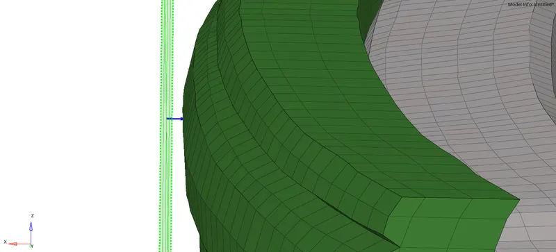
CREATION OF GAP BETWEEN RWALL AND OBJECT:
- There has to be a gap present between the rwall and object to crash for better result output.
- For creating the gap as there is no gap present in the bumper and the rigid wall as the co ordinates of the temp node is given which is located in the mid bumper so here we can create gap between bumper nad rwall by increasing the x co-ordinate.
Image of gap created:
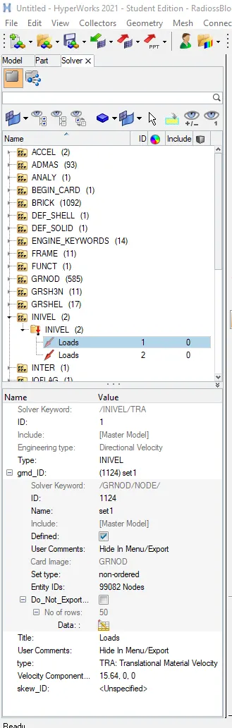
Creating Velocity:
- Initial velocity is 35mph
- We get 1mph=0.447ms, there fore 35mph=15.6464ms.
- Go to solver browser>create>Boundary conditions>Inivel.
- Apply the parameters and select whole nodes of the components to experience initial velocity.
Images of Initial velocity created:
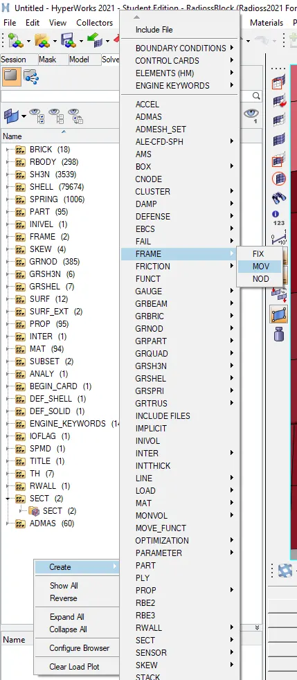
CREATING FRAME FOR ANALYSIS:
- To create frame . right click on browser>create>frame>mov>select 3 nodes for axis>create.
- Rememeber while creating loacal co-ordinates, slect the nodes in such a way that the z-axis should be in the direction of initial velocity applied.
- Create a frame and assign FRAME on each section accordingly.
- Now assign a section card in the next process.
- Refer the below image as shown in below image.
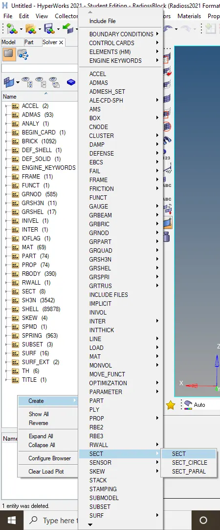
Creating sectional parts for analysis:
- We need to create sections at A- pillar, shot gun, rails and bumper plates in order to study the sectional forces.
- We should know how the forces are transmitted from the bumper to the dashboard and the rate of deformation. It is done in order to ensure the safety of passenger.
- TO create a section part go yo browser>create>section>SECT.
Image for creating section:
- Select three nodes for making frame. For creation of frame you have to slect 3 nodes for the section card you have to select again those partcular 3 nodes( N1,N2,N3). In this 3 node taken as reference frame for calculationg nodes across the section.
Image for selecting 3 nodes in frame card.
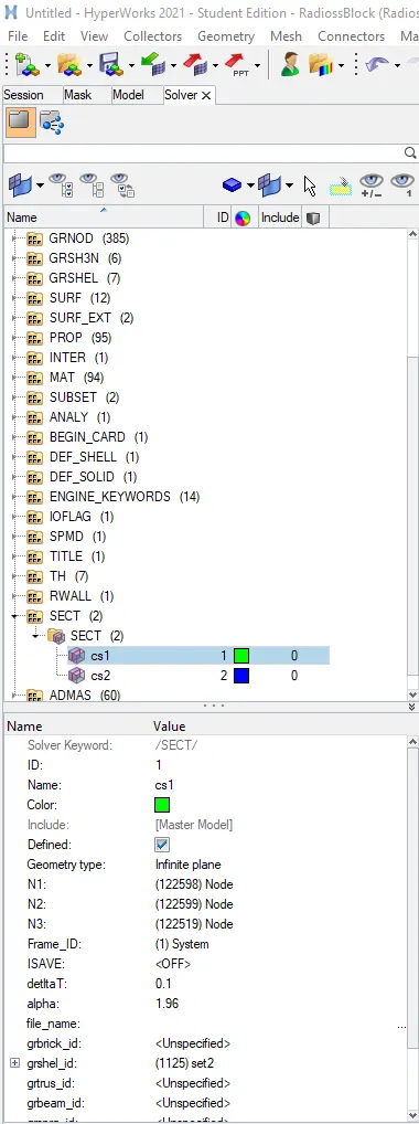
- Then under the frame select Frame_ID you have to select the frame made earlier .
- Put the values of delta T and alpha as 0.10 and 1.96 and iframe value as set to 12.
- Create grshel_ID select a section of elements on a component where we should calculate forces going through them.
- Rememeber the plane created at the section must be perpendicular to that component.
CREATING ACCELERATION NODES:
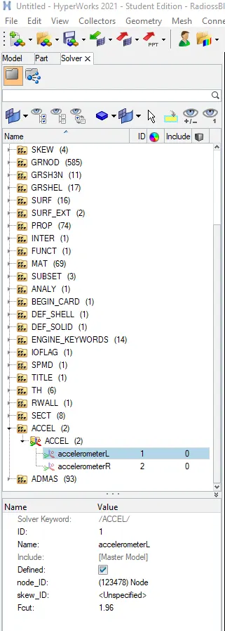
- Creating Accelerometer on both sides of the B pillar.
- An accelerometer is a basic technology that converts mechanical motion into an electrical signal. It is an electromechanical device that measures acceleration forces, whether they are caused by gravity and motion.
- Go to browser>Create>Accelerometer>select node.
- Create accelerometer on both sides.
Image for creating accelerating nodes:
Creating Springs for Intrusion on the dash wall:
- Intrusions here means how much displacements the driver is facing near the brake and acceleration pedal.
- We are planting spring elements to study the intrusion.
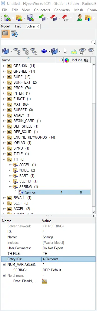
- Create 2 parallel spring elements from the indicated nodes(66695,6624) as requested in the question at the crossbeam.
- Springs can be created from the 1Dpanel>Springs.
- Slect the node at required node id as shown below and then, select another node on the other end to create spring, this is done to see how the cabin is crushing during crash.
- Also create a property for the springs and assign the property to those springs.
Image for created springs:
Deleting existing TH and create New cards:
- Delete all the necessary TH files and create the time history files for the boundary conditions such that we need to create for the current frontal crash model.
- This helps in reducing the simulation time and solver only creates TH for required outputs.
Image for required TH files :
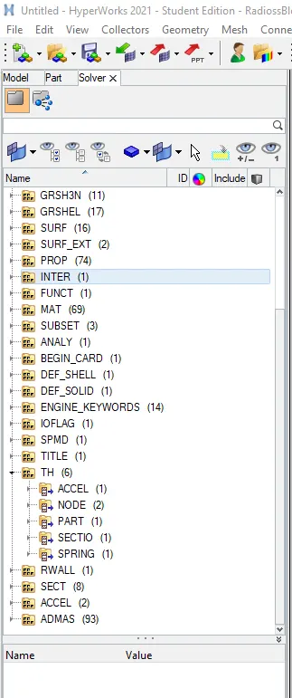
- Acceleromter, nodes for intrusion, Parts, Section, Springs are the required Time History files that we need to run a simulation for the required Outputs.
Editing Engine Cards:
- As recommended in the given challange check all the thses cards and assign the valus accordingly.
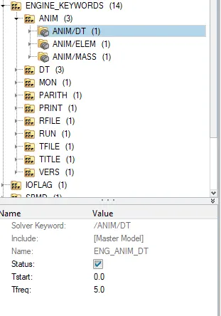
- Eng_ANIM_DT, ENG_RUN, ENG_DT_NODA are the cards for editting the required values.
Images for Engine Cards:
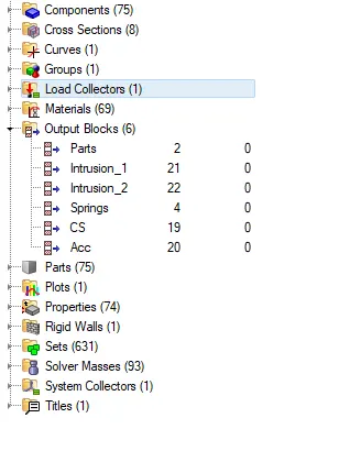
Creating Output block:
- Output blocks contain the data are obtained after running the simulation.
- In order to create 5 different outputs block for different sets of data.
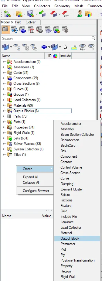
- For creating Output block go to model browser>Create>Output Block> and assign the required outputs for created materials such as accelerometer, Cross sections and intrusion springs.
Image for created Output blocks:
Checking for Errors:
- After running the simulation in tools>Model checker.
- We can easily identify and delete unused sets and empty sets using tools>empty or unused option.
- Also check for springs and accelerometers nodes that are selected properly or not.
Running the main simulation:
- Next run the simulation and by going to Analysis>Radioss> and check for the following parameters as shown in below image.

Analysis Report:
- As now the simulation is completed, next step is to check for the energy, mass errors from the generated report which is 0001.rad output file in the input specified folder.
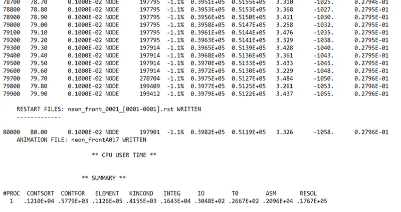
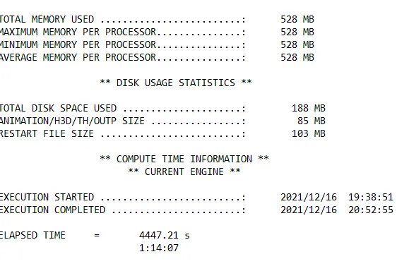
- From the analysis report we can say that -1.1% is the energy error as it lies between the recommended range of -10% to +5% error.
- Mass error of 0.0279 which is negotiable quantity of mass is added during the simulation.
- Total simulation time is 4447.21s which is 1hr 14minutes approximate time to complete the simulation.
- And No of cycles as 80000.
Animation file of simulation:
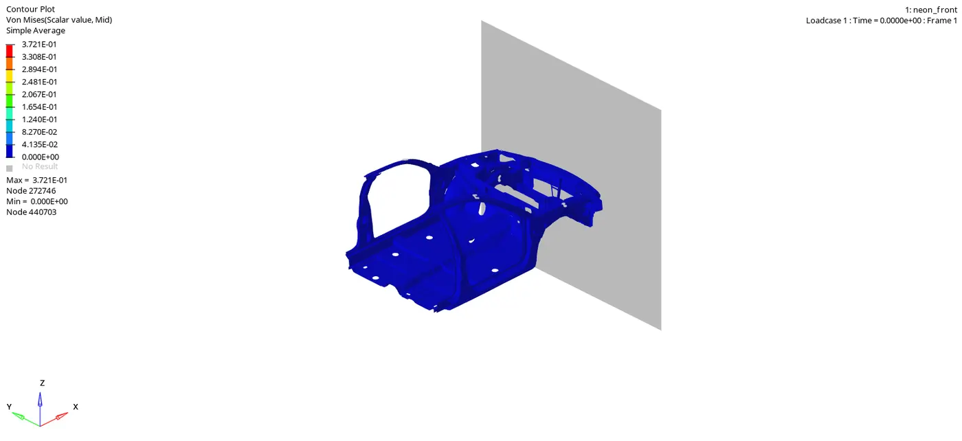
- For viewing the simulation animation click on result in the solver screen after running the simulation or browse for .h3d file in input specified folder and open HyperView.
- Change the view in contour and apply the parameters like von-misses, displacement, plastic strain by selecting the displayed components with simple averaging method.
Animation for Frontal crash analysis- Von misses stress.
Animation for Frontal crash analysis - Displacement.
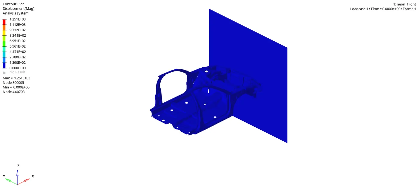
- From the simulation, we can state that initially, the bumper starts experincing the crushing then the bumper forces are transferred to left and right rail and then rail forces are transferred to A pillar Left hand and right hand side.
- From the von-misses stress plot we can say that stress distribution is quite good in the vehicle after the crash. There are very few areas we can see stress concentration.
Generating the plots:
- After running the simulation we can view the graphs of output block which we created before running the simulation.
- For viewing of graphs switch to HyperView 2D and browse for T01 file in the input specified folder.
Graph of Global variables energies:
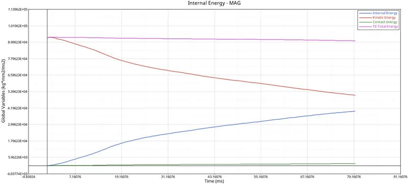
Internal and Kinetic energy:
- The changes in Kinetic and internal energies occur at the exactly when BIW component comes in contact the rigid wall. So the BIW loses kinetic energy throughout the simulation due to decrease in velocity. At the same time, it absorbs the forces , and this results increase in internal energies and as a reslut deformation occcurs .
- From the above graph, we can see that Hourglass energy is almost negligible since we used improved integrated element formulation(QEPH).
Contact energy:
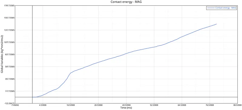
- Contact energy is a type of energy that is formed when one element meets the other or neighbouring elements. The opposing force created by this element forms the contact energy. In this case, it increases after 5ms, and the model starts deforming in such a way that penetration of nodes occurs.
- The increase in contact energy affects the overall energy of the system. hence there is decrease in total energy of the system.
SECTIONAL FORCES: On rails
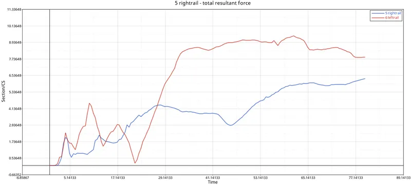
- We can see that top view of the simulation, left rail deforms more in the beginning at around 10ms with around 4.5KN/mm.
- For right rail the peak energy is at 55ms with force of approximately 9KN/mm.
On shotguns:
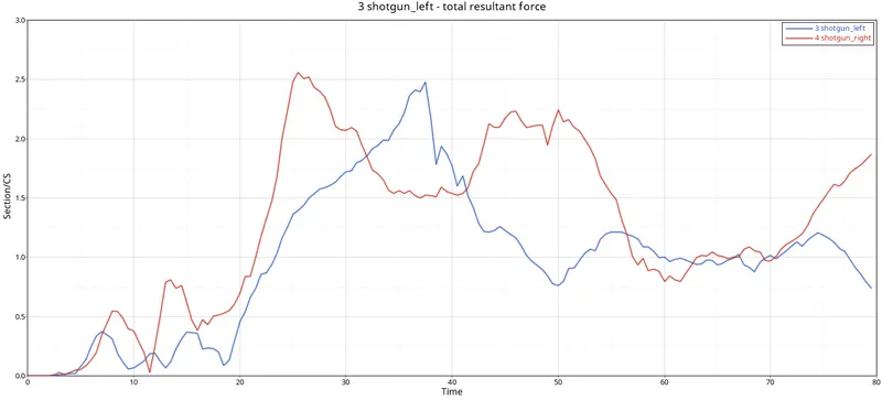
- As crash is happening continously, the shotgun will meet the rigid wall as shown in animation. The rigid wall also experinces the force directly to shotguns and hence there is increase in the sectional force as seen in the graph.
- The froce in the right short gun is more linear compared to sudden shifts in the left short gun.
- The max xross sectional force at the left shoty gun is 5Kn/mm at t=30ms where as the max cross sectional force on the right short gun is 2.1KN/mm at t=50ms.
On intrusion Springs:
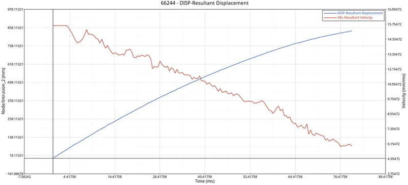
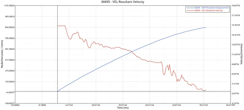
- Here we can see that after the frontal crash impact on BIW the intrusion is recorded in the from of displacement. This intrusions 66695 and 66244 are near to driver brake and acceleration pedal..
- There is a huge deformation recorded at the intrusion nodes near the front section and value is shown in negative x axis for displacement and as well as velocity of the springs.
On a-Pillars:
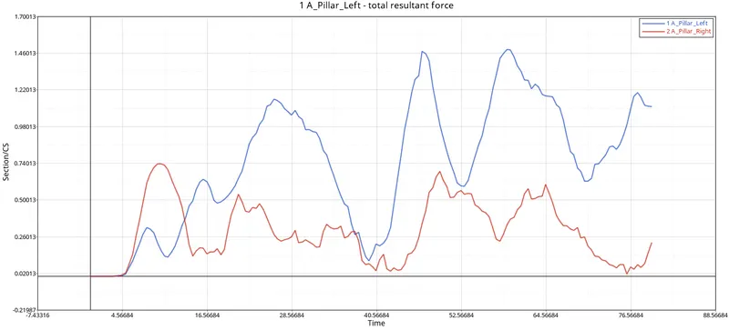
- We can see that max cross sectional force at left A -pillars is around 1.5KN/mm at t=58ms and at right is 0.75KN/mm at t=5ms..
- During the frontal crash, the sectional force reaching the A -pillars are coming from the rails and shotguns, hence the force at the A-pillars will be less when compared to front sections.
Acceleromters:
- As we know that acceleration is the rate of change of velocity. To measure the acceleration we placed accelerometer near the rocker of B-pillar on both sides.
- Once the car hits rigid wall with initial velocity, the acceleartion of the vehicle during the crash is not same accross the structure this is due to retardation of the vehicle at various velocities. From the below graphs there is a sudden increase in the accelartion, this might be because of some vibration that occurs during the crash with respect to the point where the accelartion is placed.
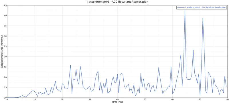
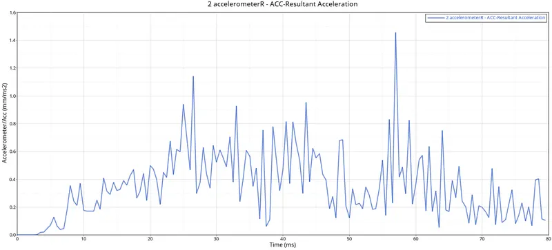
- Maximum accelaration at left hand is 4.5mm/ms2 at t=63ms.
- Maximum accelartion at right hand is 1.4mm/ms2 at t= 55ms.
Learning Outcomes:
- Importance CoG and its recommended position.
- Usage of different types of interfaces and its applications in different scenarios.
- Creation of Initial Velocity, Accelerometers and intrusions, Frames, Sections, and local co-ordinates.
- Simulation run, animations are captured and graphs are plotted.
Conclusion:
- All the requireed objectives are performed according to the question.
- Frontal crash analysis was carried out on the given front half of a BIW model of the Dodge neon as per the given requirements.
- From accelerometers it is clear that there are more vibrations on the right hand side than left hand.
- From the generated graphs we can state that where energy differences are observed between the bumper plates, rails, short guns and A- pillars.