Assignment 6-Frontal Crash Simulation Challenge
|| ||
FRONTAL IMPACTS ARE RESPONSIBLE FOR MORE DEATHS AND SERIOUS INJURIES THAN ANY OTHER ACCIDENT TYPE.
A Detailed report on Frontal Crash Simulation (Full width Rigid Barrier) for BIW.
Abstarct : Frontal crashes are responsible for more deaths and serious injuries than any other accident type. A typical scenario is a head-on collision between two oncoming cars at moderately high speeds. In most collisions of this type, only a part of the vehicle front width structure is involved, In recent years car structures have become stiffer. This has helped to reduce lower leg and head injuries as the passenger compartment is less prone to collapse. Higher structural stiffness however also means higher compartment decelerations, which need to be dealt with by the restraint systems in the front and rear seats during the crash. These decelerations can lead to severe injuries, especially to the chest of the more vulnerable, smaller or elderly occupants.
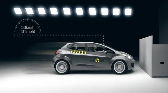
Euro NCAP tests cars against a rigid barrier with full overlap at a test speed of 50 km/h. A small female frontal impact dummy is seated in the front driver’s seat and in the rear passenger side seat.
Objective : Running a Hypermesh model with 'RADIOSS' Interface with all the necessary parameters and understanding the concept of Frontal Crash Simulation.
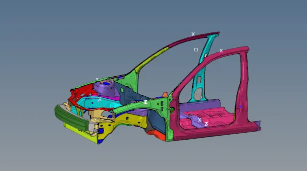
Explaination : Understanding the Project, took an overview of frontal crash for BIW .
Procedure :
- Importing File Of neon_front_0000.rad in hypermesh software using radioss interface.
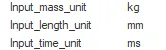
- Checking the Input Mass, Input Length, Input Time values in terms of [Kg mm ms].

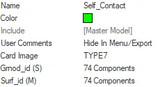
- Creating a new interface group in radioss which is named as self contact and assinging the good parameters to understand the simulation properly.



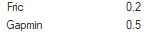

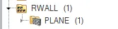
- Creating a Rigid body for frontal impact.
solver tab > RWALL > create > plane
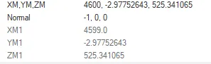
 Select a node in front on bumper and assign the values to create a Full Rigid wall. Consider friction valuea as 0.1.
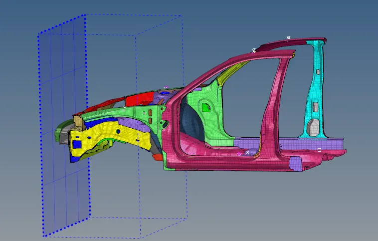
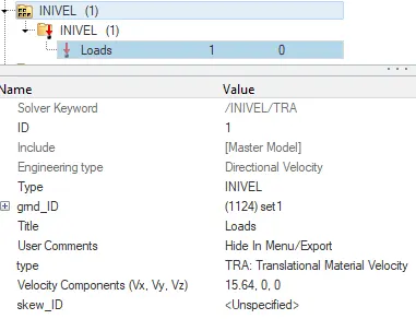
- Iniating the initial velocity of 35mph in solver tab > invel > Velocity Componets Vx
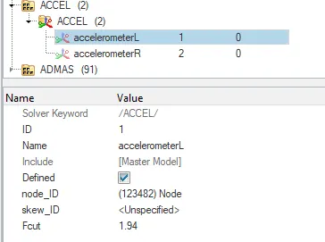
- The next step here we need to create is acceclometer node to awake the boundaries, Here Accelometer is created in Output Blocks > create > accelometer. Pick a node randomly on the rocker arm around the location of 172715. Do that on Left rockerarm and Right rockarm

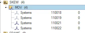
- After Creating the accelometer nodes on the rail we need to create a frame > movable which will give the value of distrotion happening to the rail and amount the velocity taken, For that reasons we need to take Skew > Moveable.
Solver tab > create > frame > movable .......Selecting three nodes N1,N2,N3 and creating a frame on accelometer Right and accelometer Left ......Then following with skew assinging the same node pick up for skew Solver tab > create > skew > movable.....
Selecting the node and assinging the skew Right and skew left....
 ....
.... ....
....
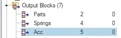
These accelometers are called back again in the model output block to get our desired results ...
 ...
... ...
...
- CREATING THE CROSS SECTIONS....
On LEFT BUMPER , RIGHT BUMPER , LEFT SHOTGUN , RIGHT SHOTGUN , LEFT A PILLAR , RIGHT A PILLAR, LEFT RAIL , RIGHT RAIL .
These cross-sections are assigned and will call in output block to get our desired results...
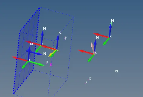
- Considering Body mass Concept and assign the correct values in the bormal physics.
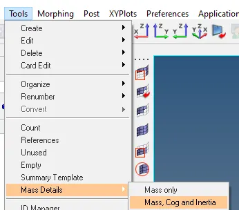 .........Picking a node in between the Biw centre and applying as per requirements.......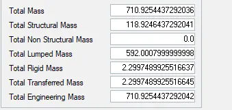
- Creating the intrustions on dash wall to notic ehow much of intia;l velocity damage is happening.
Checking the Penetrations and model check up
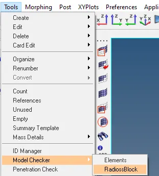 .......
 ....
....
.............................................................................................................................................................................................................................................
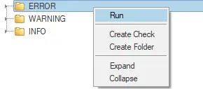
NOW THE SIMULATION IS READY TO RUN >>>>>>>
Analysis > radioss > include connectors > -nt 4 > save as > Radioss

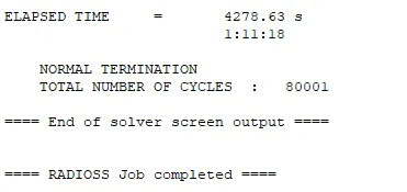
...The simulation runs properly if no errors are there and gives a 0001.out results file check into that and observe the plot differences...
....................................................................................................................................................................................................................................................
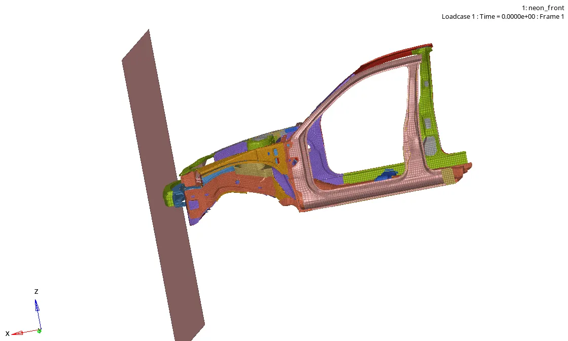
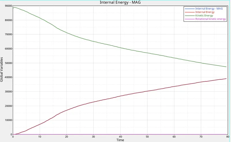
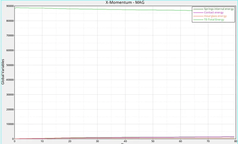
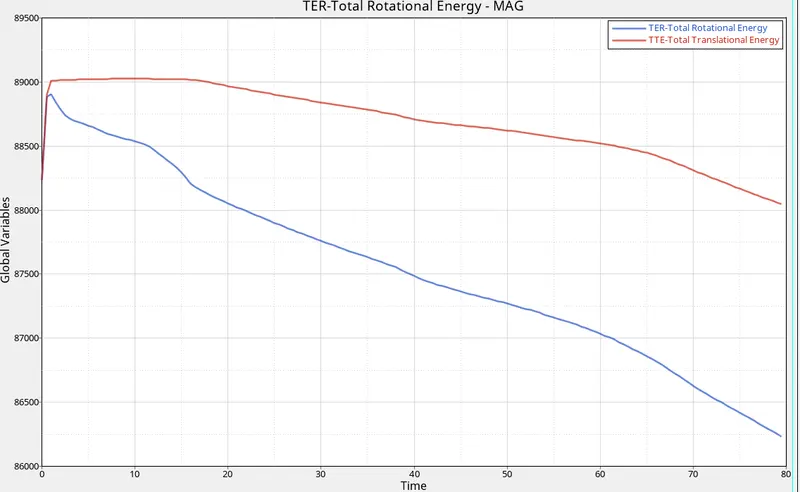
We can find the shotgun Distortion, acceleometer distortion, bumper distortion slight changes in A pillar ....Lets Plot the graphs and observe the changes..
CONCLUSION :
This test places high demands on the restraint systems in front seating positions. Strict limits are placed on the decelerations of the chest and on the degree of chest deflection and this, in turn, encourages manufacturers to fit more sophisticated restraints.
Understood the simulation and complete analysis of passenger safety test front rigid wall deformable test with radioss....and making quick changes to ever stive for passenger safety first.