Assignment 6-Frontal Crash Simulation Challenge
Aim: Frontal Crash Simulation of a Dodge Neon BIW using Radioss and preprocessing using Hypermesh and Hypercrash.
Objective :
- Sectional force in the rails at location of indicated node 174247.
- Axial force received on the rails from bumper.
- Shotgun cross sectional forces.
- A pillar cross section.
- Acceleration curve received on the accelerometer at base of B pillar (on B pillar rocker).
- Intrusions on the dash wall 66695,66244.
Parameters setup and checks:
- Check unit system and either follow[Mg mm s] or [Kg mm ms].
- Create appropriate interface ,friction 0.2 and recommended parameters.
- Make sure of no penetrations and intersection.
- Correct rigid bodies if any issues.
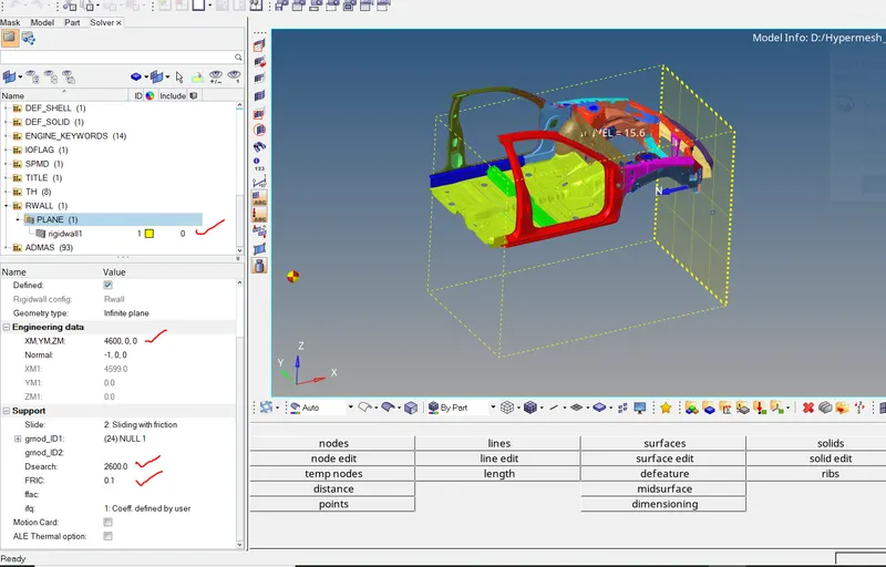
- Create rigid wall with friction 0.1.
- Compare the model weight with the full scale 300k nodes model and use added masses to reach target weight 700kg while getting CG about the required range.
- Initial velocity 35 mph.
- Use model checker to ensure good quality.
- Time-step :0.5 to 0.1 microseconds.
- Run 80 ms.
Procedure:
1) Check unit system and either follow[Mg mm s] or [Kg mm ms].
To check the unit system goto neon_front_0000.rad and open the file. It will show the unit system.
we can see the units are in Kg mm ms.

Now Open the hypercrash and perform the peneteration check and and adding the mass.
Peneteration & Intersection
Peneteration - is defined as overlap of material thickness of shell elements.
Intersection - is defined as elements that actually pass completely through one another.
All models and espacially impact models should be checked to make sure there is no peneteration or intersection.
This may affect the results and should be removed.
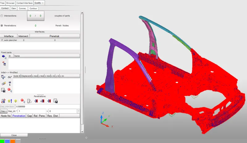
There is no Peneteration or intersection present in the model.
Adding Masses.
Since this is a reduced model the vehicle weight and COG - center of gravity is not required at this point.
The model weight while importing was 188kg so we will be adding masses to bring upto 700kg in appropriate places so that the COG is at CH CBN SEAT REINF FT.
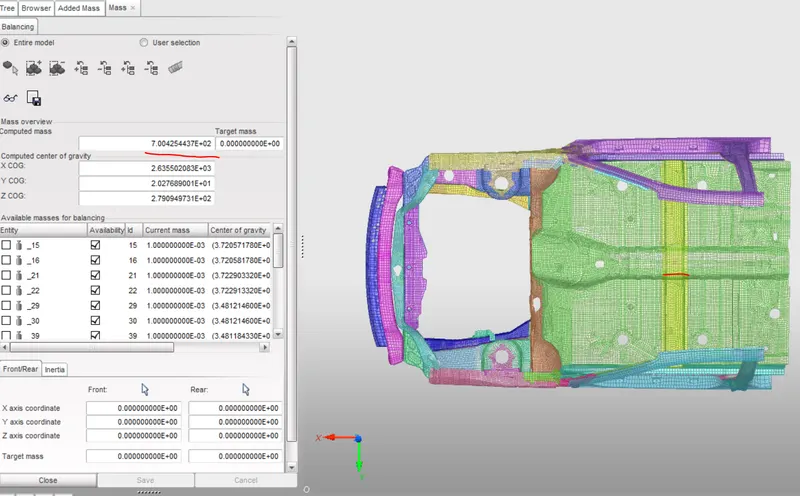
After adding additional masses Weight is 700kg and CoG is coming in correct place.
Now export the file in Radioss. Goto file - Export -Radioss
Then Import the file in Hypermesh and do the changes.
Contact interface.
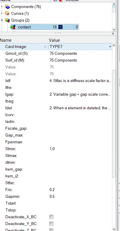
Type7:Node to surface :
This interface si,ulates the most general type of conatct and impacts.TYPE 7 interface has the following properties.
1)Impact occur between a master surface and set of slave nodes similar to Type 5.
2)A node can impact one or more master segments.
3)A node can impact either side of surface
4)Each slave node can impact each master segment except if it is connected to this segment.
5)A node can impact the edge and corners of a master segment. None of the previous interface allows this.
The Recomended proterties are :
1)Igap = 2 Variable gap took into account.
2)Gapmin =0.5
3) Inacti =6 remove initial peneterations wherever possible else reduce to less than 30% of defined gap.
4)Istf = 4 stiffness based on softer segment.
5)Stmin= 1kN/mm minimum stiffness in contact to avoid too soft contact.
6)Idel = 2 remove slave nodes from contact because of element deletion.
7)Iform= 2 Frictional forces are calculated on the basis of stiffness parameter.
Create Initial Velocity Card.
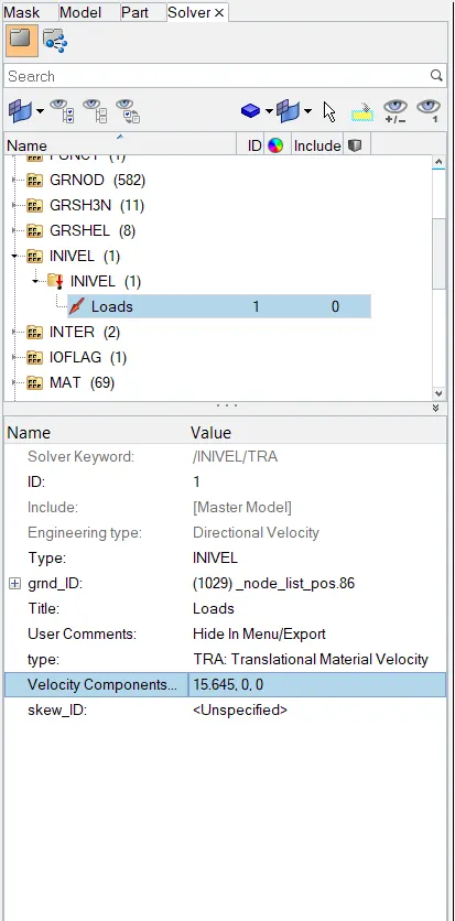
Goto Solver BC- Boundary condition - INIVEL - Create.
Initial velocity is 35mph. Convert mph into ms
1mph = 0.447 therefore 0.447X35 = 15.645
Create Rigid Wall
Rigid wall entities provide a method for treating a contact between a rigid surface and nodal points of deformable bodies.Initially a node is created and it is translated to some distance and using this node coordinate as a reference the rigid wall is created.
Goto Solver browser - created Rwall - Plane
Set the friction value as 0.1 & Dsearch as 2500 that covers entire BIW.
Create Sectional Forces.
Creation of a sectiion at various points in order to study the sectional forces.To check how the forces are transmitted from bumper to Instrument Panel and the rate of deformation. It is carried out in order to ensure passengers safety. Certain components have to crash deform more than others so that the forces are distributed correctly leaving very little force to transmit to cabin.
Goto solver browser - create - section - SEC
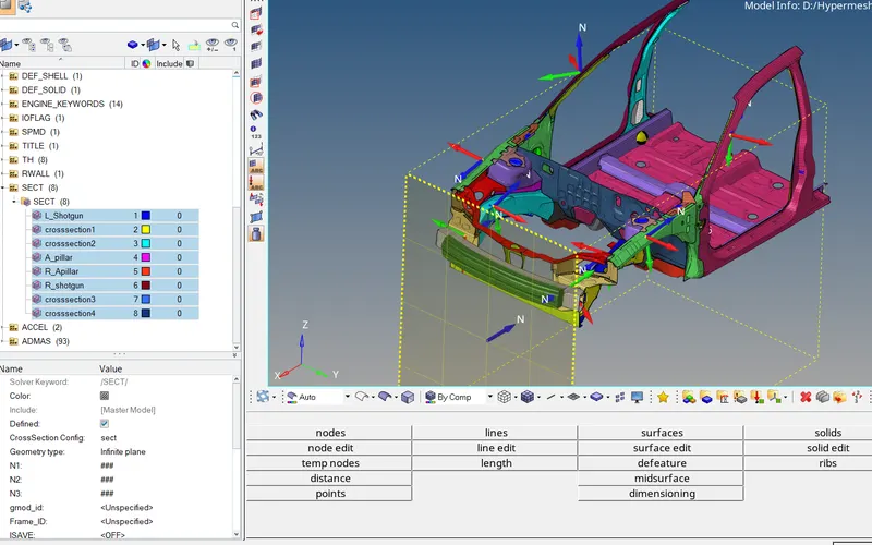
Define the nodes with ref to Axis of the frame.
Enter the value of DeltaT = 0.1
Define Cutting Plane by group of elements and its orientation by group of nodes (grshel_id). Section will be created.
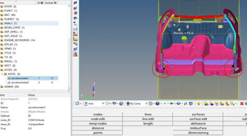
Create Acceleration Nodes:
Creating Accelerometer at both sides of B Pillar.
An Accelerometer is a basic technology that converts mechanical motion into electrical signal. It is an electromechanical device that measure acceleration forces caused by motion or gravity.
Goto Model browser-create-accelerometer - select Node_Id-select node-Proceed.
This will show the rate of deformation.
Creating Spring element:
Spring element needs to be created to study the intrusion(Forces inside the cabin causing deformation). Create 2 parallel spring elements from the indicated nodes (66695,66244 till the crossbeam). Provide properties.
Goto 1D Panel - Springs - Provide the node id as mentioned.
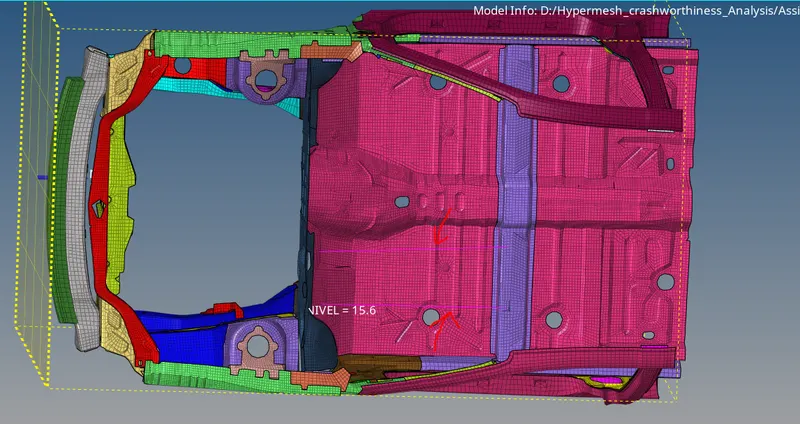
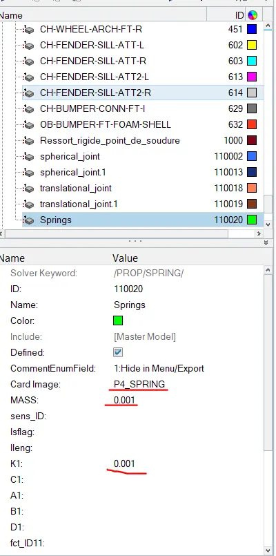
Goto model browser- create-property-rename as spring. Select P4 as property card and mass 0.001 and stiffnes 0.001.
Assign the propety to spring elements in components.
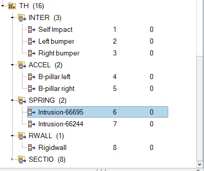
Requesting TH for Intrusion Spring,Accelerometer,Section force.
Delete existing TH and create new.
All Global Variables(Internal energy, Kinetic energy,contact energy Hourglass energy.) they are default
We have to call additional time history files for boundary conditions that we have created for frontal crash model.
we can create the output request from Solver browser.
Solver browser - Rightclick - create- TH-Select output request.
| Output request | Boundary Conditions |
| Inter |
self impact left bumper & headlight Right bumper & headlight |
| Accel |
B pillar left B pillar Right |
| Spring |
Intrusion - node 66695 Intrusion - node 66244 |
| Rwall | Rigid wall |
| Section force | All |
Time step control
ENG_RUN = 80ms
ENG_ANIM_DT = Tfteq =5
ENG_DT_NODA - 0.001 Tscale factor = 0.67
ENG_DT_BRICK = 0.0001 Tsclae factor = 0.9
ENG_DT_INTER = 0.0005 Tsclae factor = 0.9
Check for Errors using Model checker option and delete the unused cards.
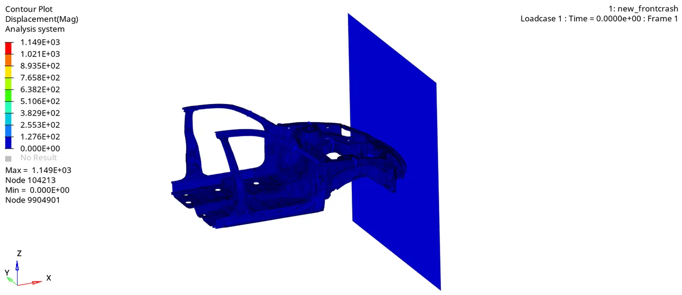
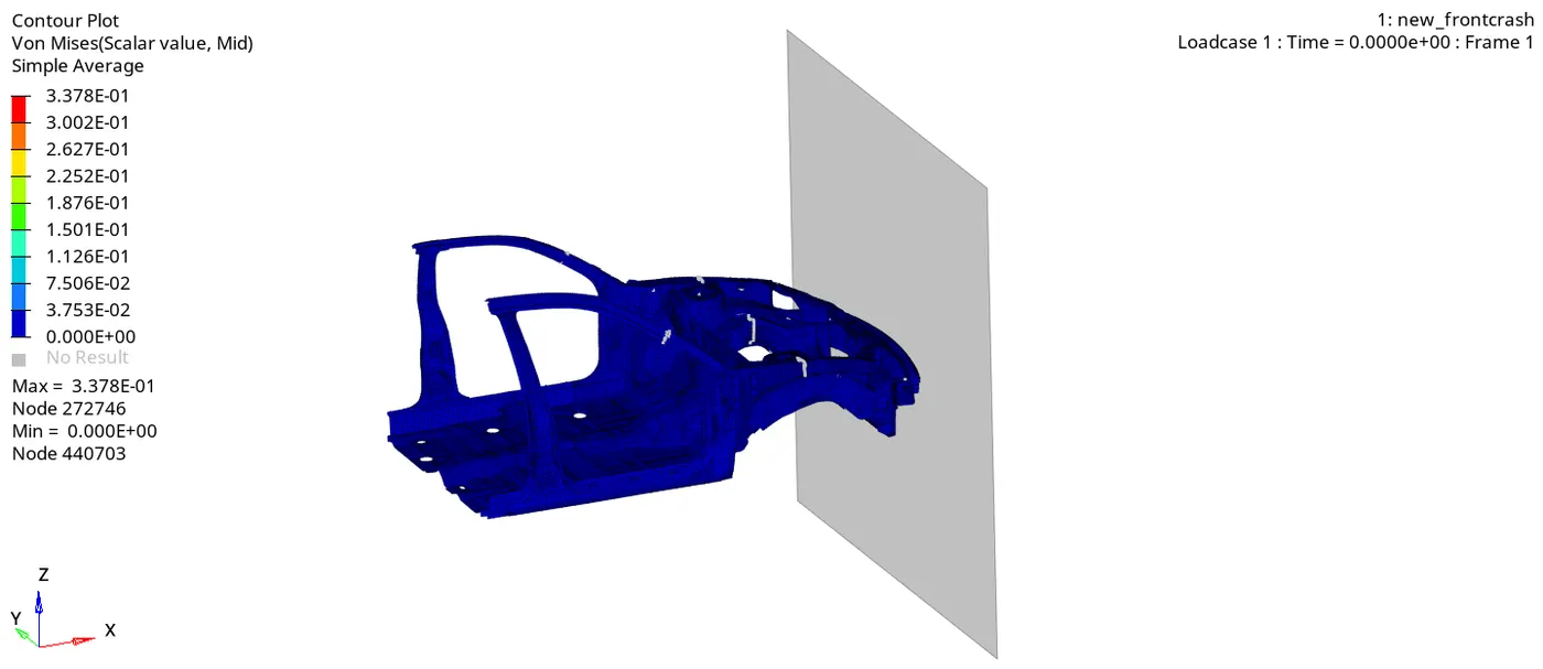
From the Simulation we can see that Initially the Bumper starts crushing then forces are transferred to left and right rail from rail it gets transferred to Apillars. At each stage forces are getting absorbed.
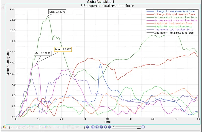
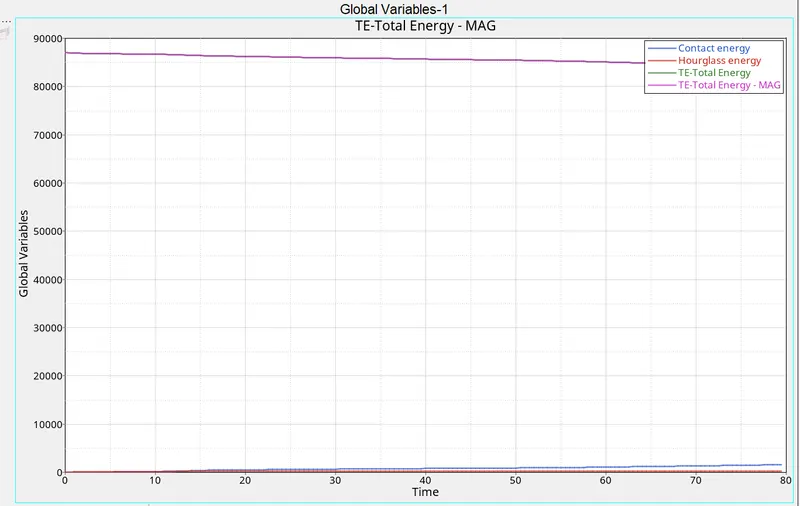
From the graph we can see maximum forces exerted at peak value and How forces are getting transferred.
Conclusion : The given model was simulated for frontal crash using radioss and results obtained were validated. The graphical results were plotted for all the test cases. From the simulation we can observed that there was minimum deformation in cabin and aslo minimum impact was found in the drive's seat area.