Assignment 6-Frontal Crash Simulation Challenge
OBJECIVES:
Frontal crash-BIW
- Check unit system and either follow[Mg mm s] or [Kg mm ms].
- Create appropriate interface ,friction 0.2 and recommended parameters.
- Make sure of no penetrations and intersection.
- Correct rigid bodies if any issues.
- Create rigid wall with friction 0.1.
- Compare the model weight with the full scale 300k nodes model and use added masses to reach target weight 700kg while getting CG about the required range.
- Initial velocity 35 mph.
- Use model checker to ensure good quality.
- Time-step :0.5 to 0.1 microseconds.
- Run 80 ms.
Output requests:
- Sectional force in the rails at location of indicated node 174247.
- Axial force received on the rails from bumper.
- Shotgun cross sectional forces.
- A pillar cross section.
- Acceleration curve received on the accelerometer at base of B pillar (on B pillar rocker).
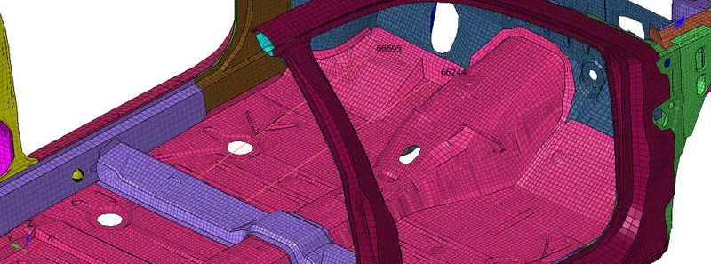
- Intrusions on the dash wall 66695,66244.
PROCEDURE:
- The Car model is showb below:
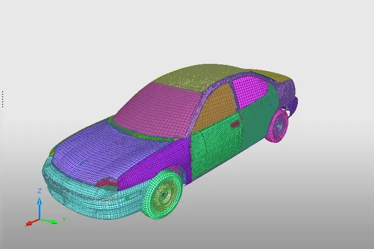
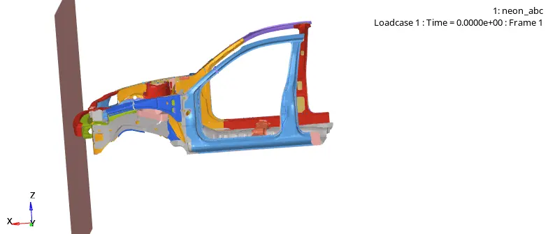
- Now we have to perform the frontal crash so for that the model is shown below:

Check unit system and either follow[Mg mm s] or [Kg mm ms].
- Now we will check the unit system for that open the 0000.rad file.
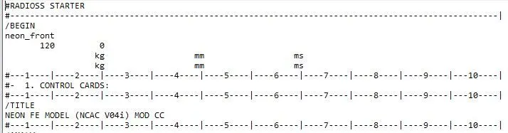
- As you can see the unit system is in kg mm ms format.
Create appropriate interface ,friction 0.2 and recommended parameters.
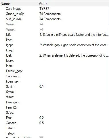
- For this we will select TYPE 7 contact interface because node to surface contact.
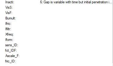
- And will assign the recommended parameteres as shwon below:
- To create TYPE 7 go to the MODEL>CREATE>CONTACT>TYPE 7
Make sure of no penetrations and intersection.
- Now to check the penetrations and intersection go to the Quality>Check All Solver connection Interface. As shown:
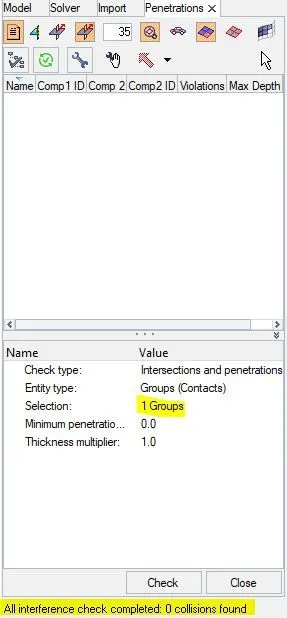
- Now we can see here, there is no Intersection and penetration.
Create rigid wall with friction 0.1.
- For this we will go to the SOLVER>CREATE>RWALL and then creat a Plane wall with friction 0.1 as shown:
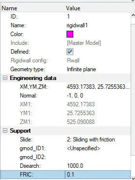
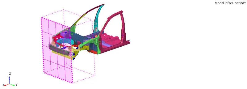
Compare the model weight with the full scale 300k nodes model and use added masses to reach target weight 700kg while getting CG about the required range.
- Now we have to align CG to the centre of the car so for that we have to add the wieght to the accordingly.
- So see the Mass of the car go to the TOOLS>MASS DETAILS
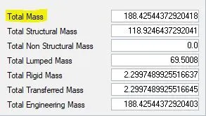
- Now we will go to hypercrash to balance the Mass. For that go to MASS>BALANCING
- So to add the mass in we have to keep in mind that component should not exceed more that 700 kg.
- To add the mass in go to the BROWSER>CREATE NEW > ADDED MASS and add the masses accordingly.
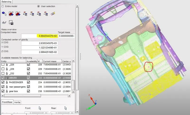
- Now in this we can see the the COG is align at the center and the mass of the car is not exceeding 700kg.
Initial velocity 35 mph.
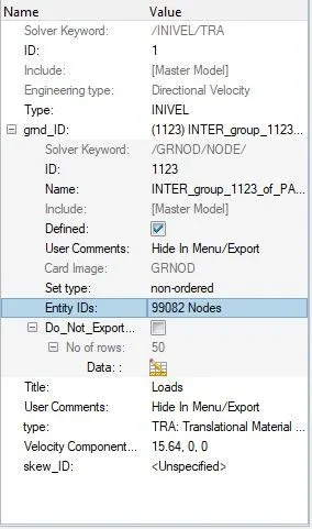
- To create intial velocity first we will convert 35 mph to ms
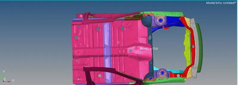
- 35 mph = 15.64 m/s
- Now to create INVEL card go to the BROWSER>BCS>INVEL
- Then add the value and create the card as shown:
Use model checker to ensure good quality.
- Now to for model checker go to the TOOLS>MODELCHECKER>RADIOSS BLOCK
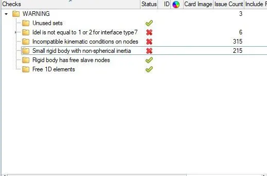
- Here the errors which were showed are removed with the help of auto correction.
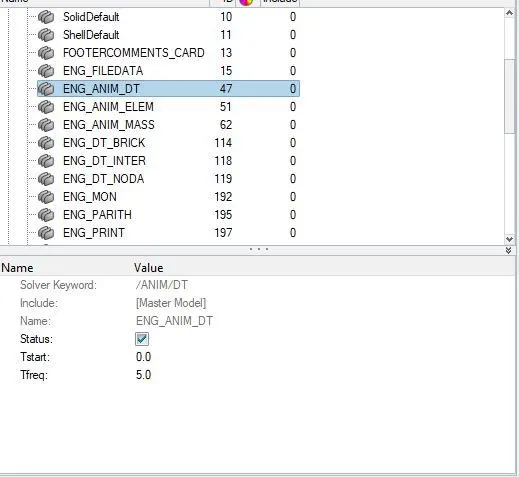
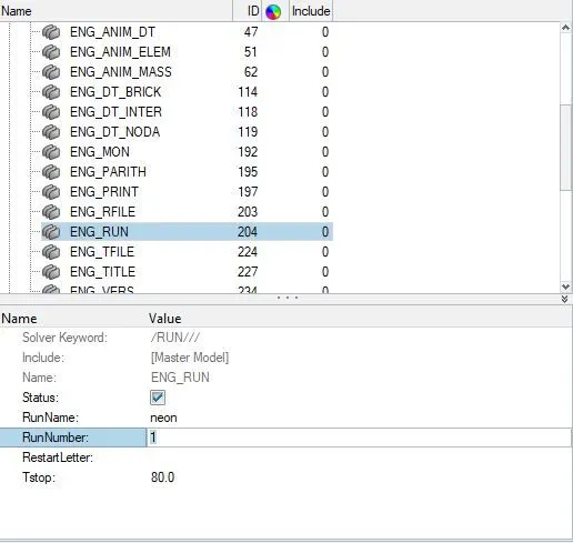
Time-step :0.5 to 0.1 microseconds and Run 80 ms.
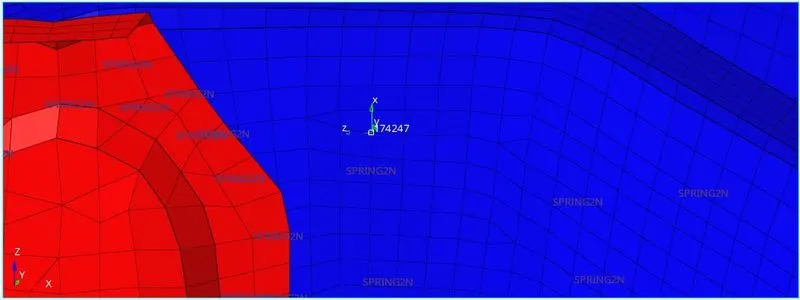
Sectional force in the rails at location of indicated node 174247.
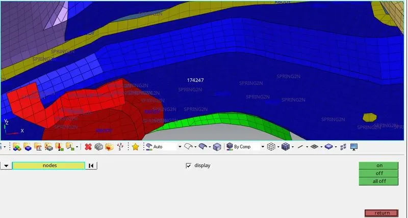
- Now to create sectional force first we have to select the node which is given, for that go to TOOLS>NUMBERS
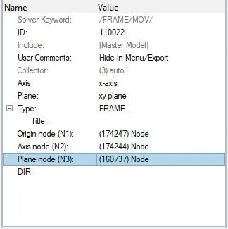
- Now after that we will create frame for that first we will create the FRAME fo that go to the BROWSER>CREATE>FRAME
 .
.
- Now we will create the section at that point for that go to the BROWSER>SECT
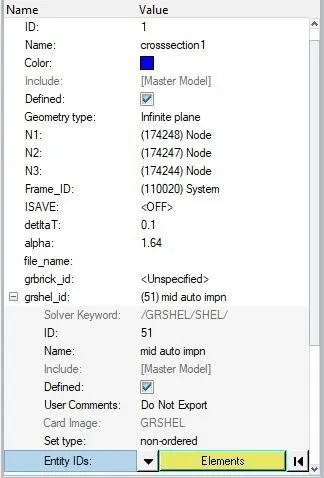
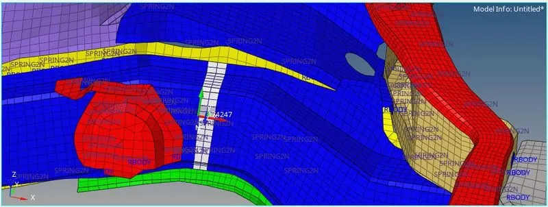
- Keep in mind that frame is we created should always be perpendicular to component.
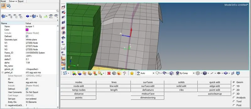
Axial force received on the rails from bumper.
- First we will create frame and after that section as shown:
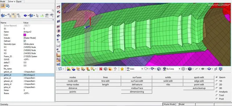
Shotgun cross sectional forces.
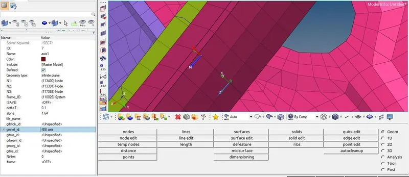
A pillar cross section.
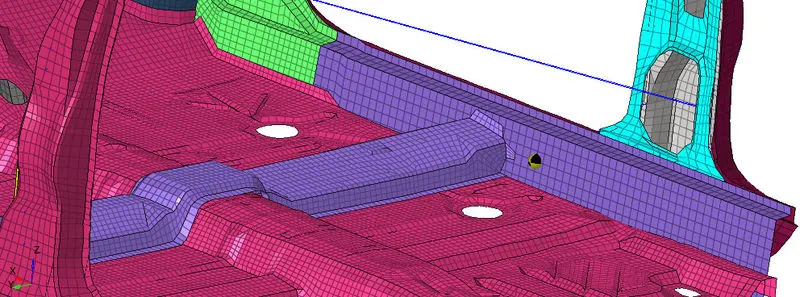
Acceleration curve received on the accelerometer at base of B pillar (on B pillar rocker).
- Now to create Acceleration curve go to the Solver>Create>Accelerometer>select nodes as shown:
- NOTE: All the above process from creating RAILS to ACCELARATION CURVE should be created on the both side.
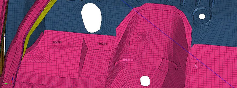
Intrusions on the dash wall 66695,66244.
- Now we will create the spring from given points parallel to each other to the Cross beam.
- First we will spot those points and after that we will go to the 1D PANEL>SPRINGS as shown:
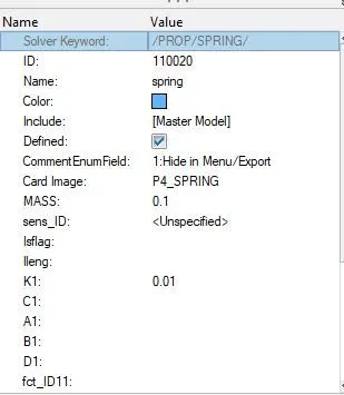
- Now assign the property to the spring as shown:
- Now all the outputs are plotted we will create the OUTPUT BLOCK
- To create it go to the MODEL>CREATE>OUTPUT BLOCK
- Now select the entity ID as a cros-section and select the cross-sections we created as shown.
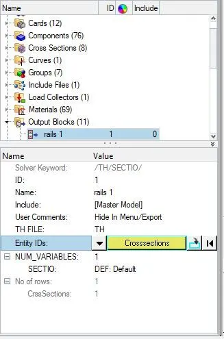
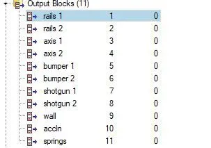
- So this is how we give the output to all the sections we created.
Now we will Run the simulation.
- For this go to the ANALYSIS>RADIOSS
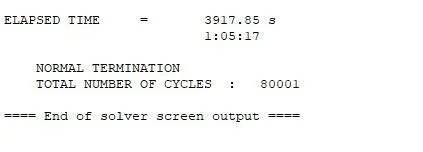
- The computation time is shown below:
- Now switch to the HyeprView and open .h3d file.
- It will look as shown below:
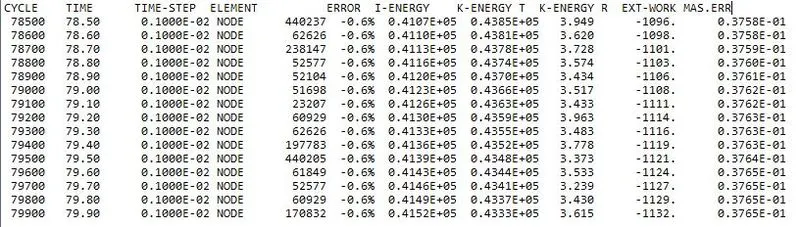
ENGINE OUTPUT FILE :
ELAPSED TIME = 3917.85 s
1:05:17
NORMAL TERMINATION
TOTAL NUMBER OF CYCLES : 80001
- As we can see, the energy error is -0.6%. It is definitely acceptable within range of -10% to +5% error. In addition to that, the mass error is 0.03213, which means that a negligible quantity of mass of was added during the simulation, possibly for the sake of time step control/stabilization. It is a rather low amount so it's still acceptable.
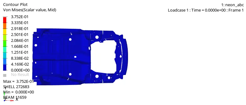
- From the Von Mises stress plot, we can say that the stress distribution is quite good in the vehicle after the crash. There are very few areas where we can see stress concentration. Generally, the stress is more in bumper region as it is the first point of impact.
PLOTTING GRAPHS:
- Now for this we will open T01 file in HyperGraph2D
- The graphs of requeste output as shown below:
RAILS 1 and 2
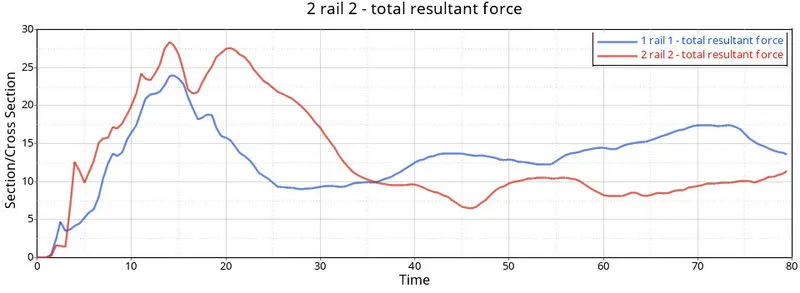
- Here you can see the peak time of the both sections is same but the C/S of Rail 2 having resultant force is 27KN/mm is more that Rail 1 having resultant force is 24KN/mm
BUMPER 1 and 2
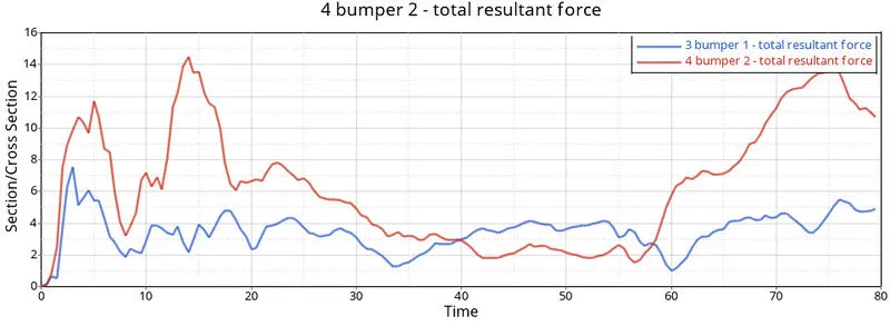
- Here the peak time of first bumper is near about 5ms with Total resultant force is 8KN and the peak time of bumper 2 is 15ms with total resultant force is 14KN
SHOTGUN 1 and 2
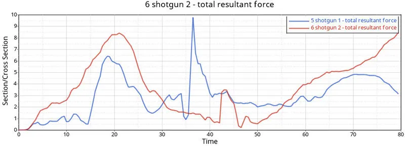
- The force in the right Short gun (section 2) is more linear compared to the sharp hills in the left Short gun (section 1).
- The maximum cross-sectional total resultant force at Shotgun 1 is10 kN/mm at t=38ms whereas the maximum cross-sectional total resultant force at Shotgun 2 is 8.5kN/mm at t=23ms.
PILLAR 1 and 2
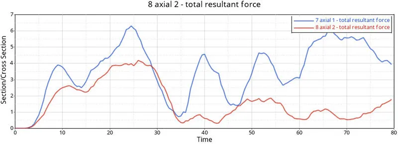
- Pillar has maximum toalt resultant force of 6.2KN whereas pillar 2 has maximum total resultant force of 4KN. Hence, the normal forces are not significant.
ACCELARATION
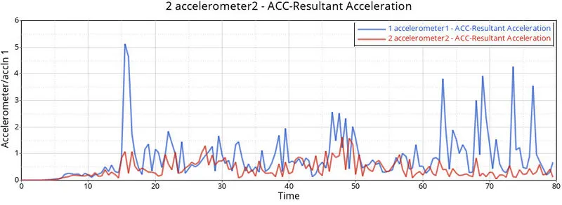
- Accelaration of the 1st point is more fluctuating that the 2nd.
INTRUSION 1 and 2
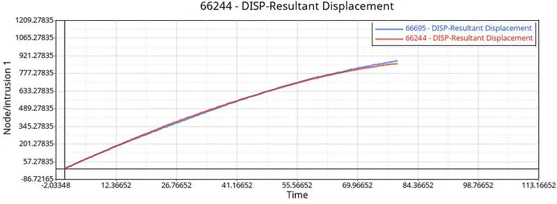
- Both the resultant displcement is same.
RWALL
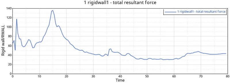
- The peak point shown where the car hit on the wall at maximum force which is 140KN at 15ms
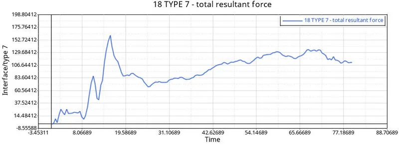
INTERFACE
| Sr NO. | COMPONENTS | TOTAL RESULTANT FORCE |
| 1 | RAILS 1 and 2 | 1. 24 KN |
| 2. 27KN | ||
| 2 |
BUMPER 1 and 2 |
1. 8 KN |
| 2. 14KN | ||
| 3 | SHOTGUN 1 and 2 | 1. 10KN |
| 2. 8.5KN | ||
| 4 | PILLAR 1 and 2 | 1. 6.2 KN |
| 2. 4KN | ||
| 5 | ACCELARATION | 1. 5 KN |
| 2. 1.5KN | ||
| 7 | RWALL | 140KN |
| 8 | INTERFACE | 154KN |
OIUCOMES :
- Able to balance the mass of the component.
- Able to create Initial Velocity, accelerometers, and Intrusions, Frames, Sections, and local co-ordinates.
- Created time history cards and output blocks
- Rectified errors in model checker.
OBSERVATION
- We saw in the animation that the most deformation took place in the frontal area and the stress is then passed to the rest of the components of the car.
- We observed that the impact of the crash is taking mostly at the frontal region of the car and by looking at this we can say that the setting area of the driver and passenger will be also impacted which can cause injury to them.
CONCLUSION:
The car crash was simulated onto a rigid wall and the various forces, accelerations and displacements were plotted, tabulated and discussed. Points were also made to potentially improve the quality of the simulation in future.