Assignment 6-Frontal Crash Simulation Challenge
Assignment 6-Frontal Crash Simulation Challenge
AIM:
Frontal crash-BIW
- Check unit system and either follow[Mg mm s] or [Kg mm ms].
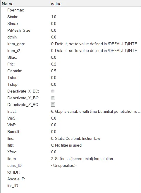
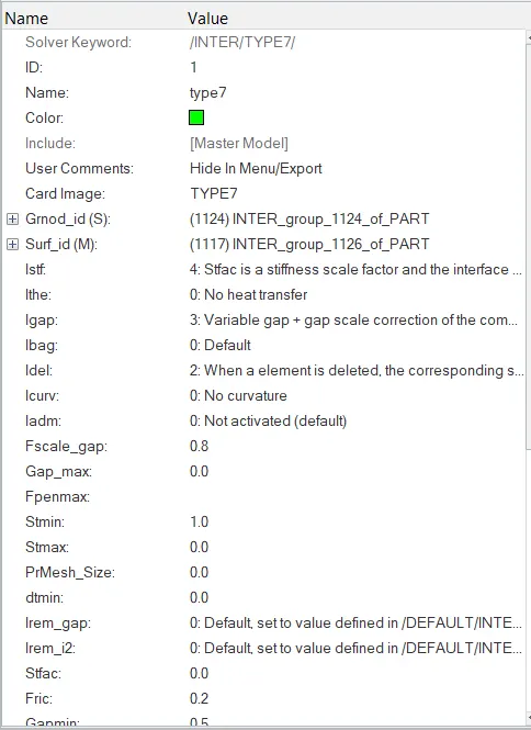
- Create appropriate interface ,friction 0.2 and recommended parameters.
- Make sure of no penetrations and intersection.
- Correct rigid bodies if any issues.
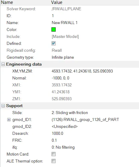
- Create rigid wall with friction 0.1.
- Compare the model weight with the full scale 300k nodes model and use added masses to reach target weight 700kg while getting CG about the required range.
- Initial velocity 35 mph.
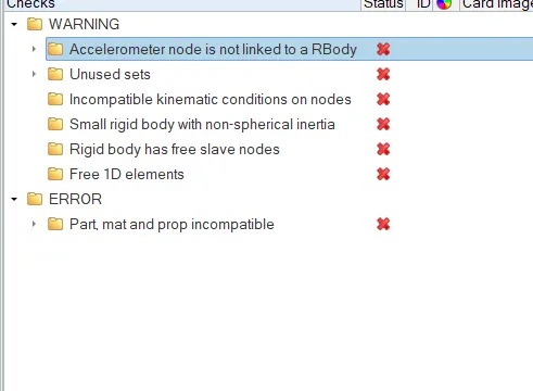
- Use model checker to ensure good quality.
- Time-step :0.5 to 0.1 microseconds.
- Run 80 ms.
Output requests:
- Sectional force in the rails at location of indicated node 174247.
- Axial force received on the rails from bumper.
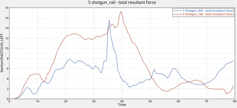
- Shotgun cross sectional forces.
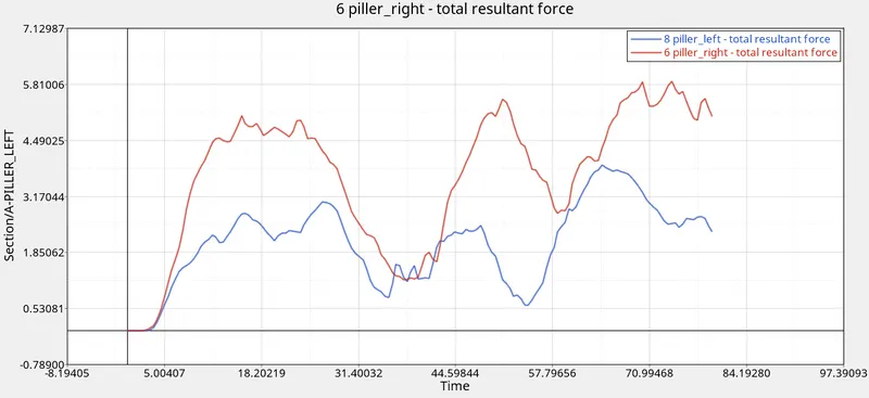
- A pillar cross section.
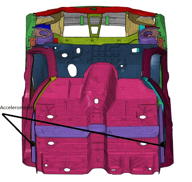
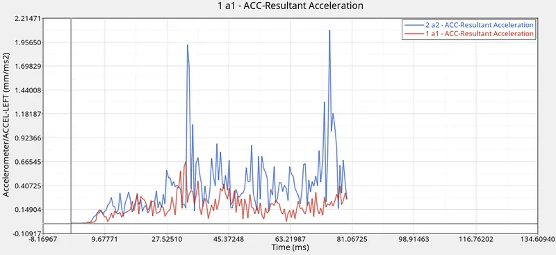
- Acceleration curve received on the accelerometer at base of B pillar (on B pillar rocker).
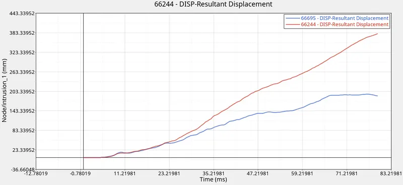
- Intrusions on the dash wall 66695,66244.
PROCEDURE:
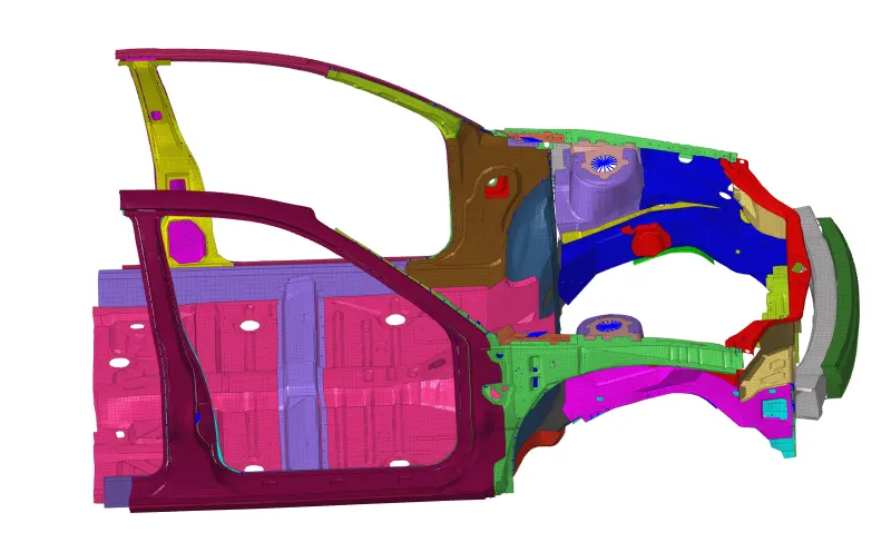
1) First we open the 0000.rad file usin a text editor to check the units used.

2) Imported the given 0000.rad file.
3) Deleting the existing type 7 contacts and then creating a new type 7 self-intersecting contact with the following values
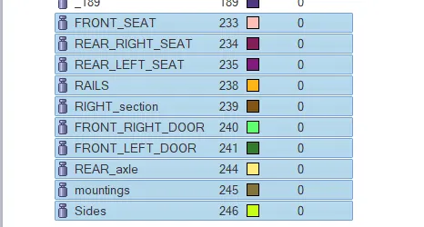
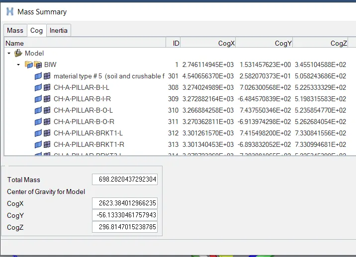
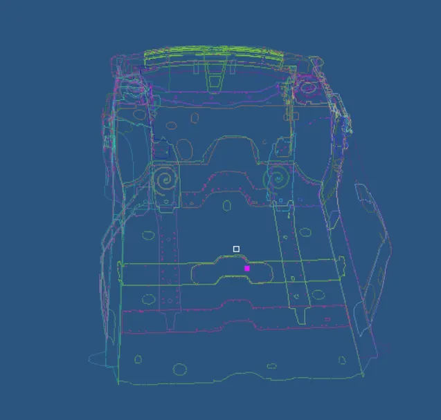
4) We then check the mass and cog of the model. We need the total mass to be 700kg so we add mass from ADMAS in Solver browser or using Hypercrash.
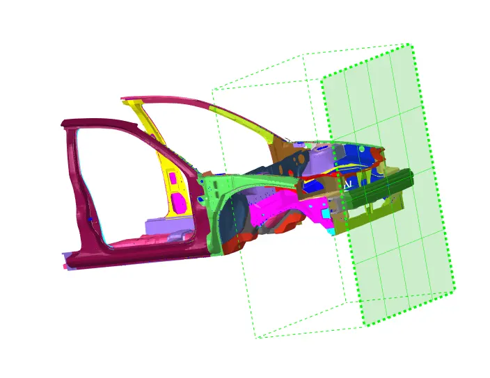
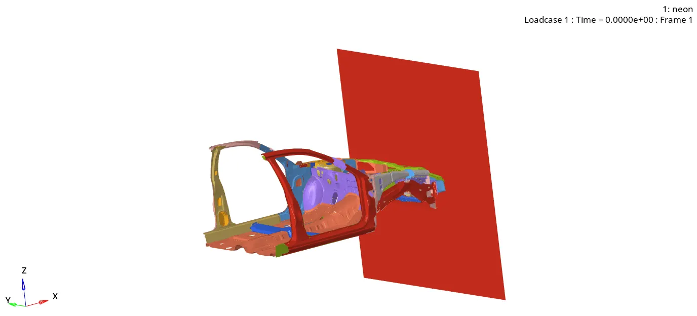
5) We now create a rigid wall by right clicking the solver browser>RWALL>PLAN and select the nodes from the bumper as a reference for the rigid wall.
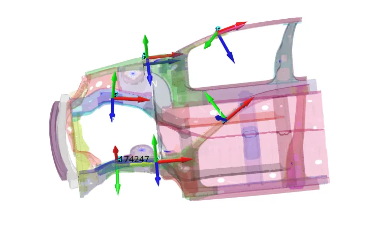
6) We created sections with the local moving parts to measure the forces which get applied on them after the collision. Sections were created from the solver browser>SECT>SECT and then the nodes and axis were defined accordingly.
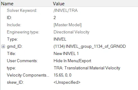
7) We then apply initial velocity to the model. To apply initial velocity we used solver browser>create BC> INIVEL and then the components were selected and the velocity of 15.64 mm/s was given in X-axis.
8) We created intrusions at nodes 66695 and 66244 by right clicking model browser and created a output block for these nodes.
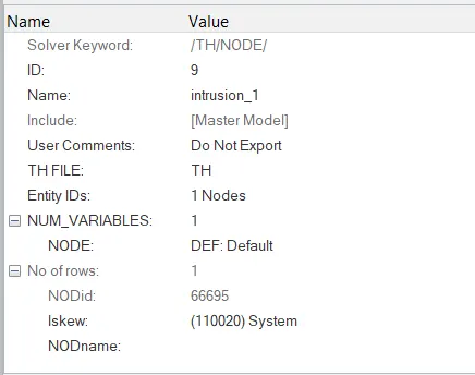
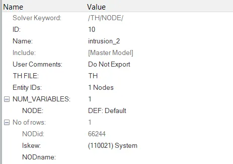
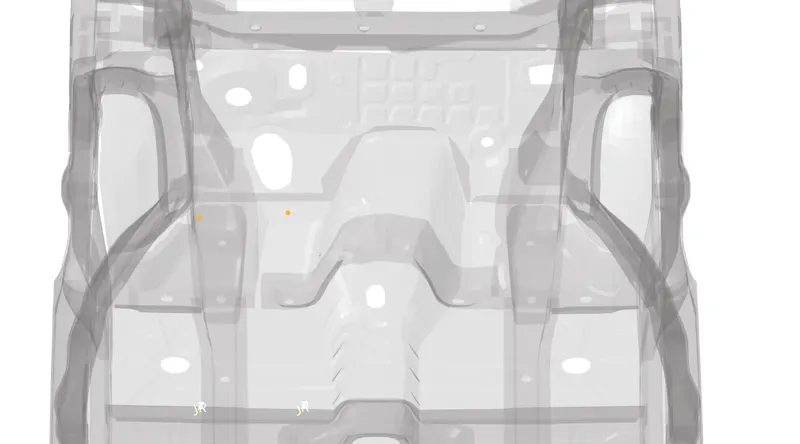
9) Accelerometers were created at the base of b-pillars from solver browser>ACCEL and selected the nodes.
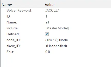
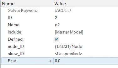
10) To measure the axial forces on the rails from bumper, we create a type 7 interface with recommended properties between them.
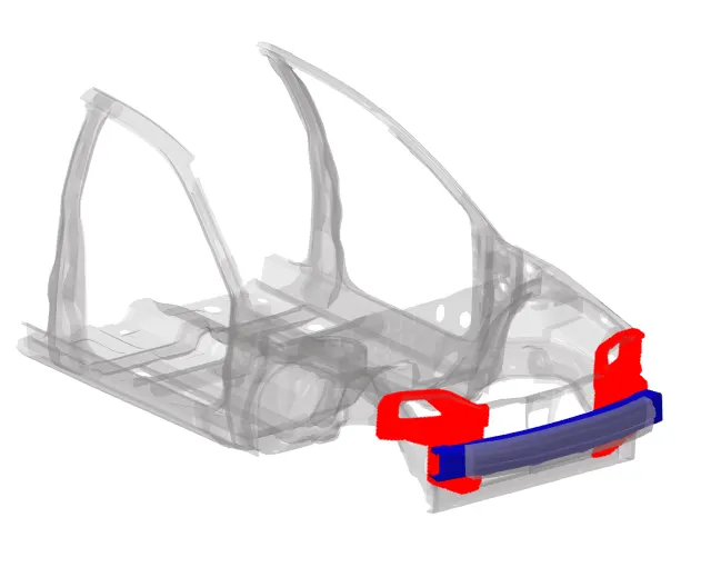
11) Output blocks for all the sections and contacts are also created.
12) After giving all the inputs, Radioss Block model check was done. No significant erros were found after the check if found any were rectified accordingly.
OUTPUTS:
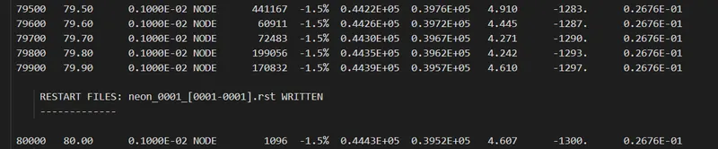
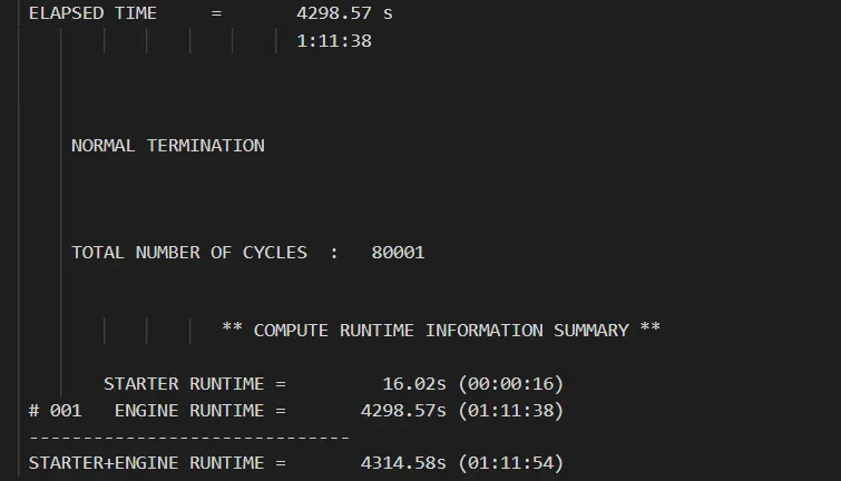
1) After running the analysis energy and mass error as well as time required and cycles are as shown below
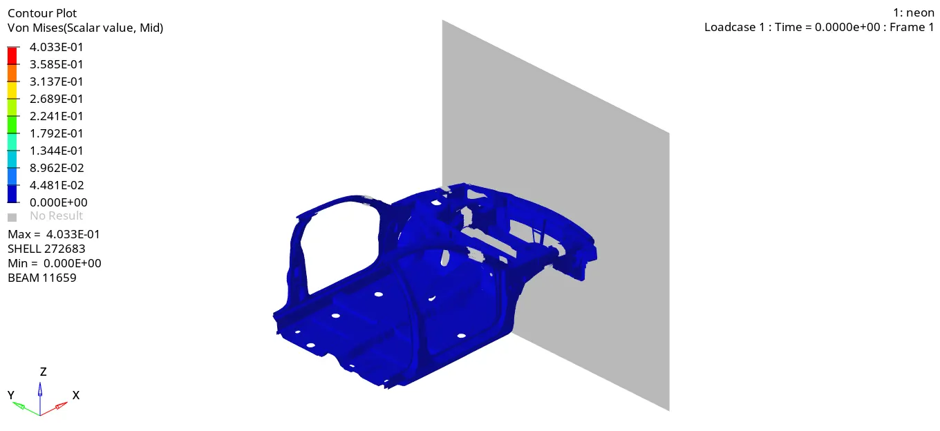
2) The deformation and Von-mises stresses experienced by the model is as shown below
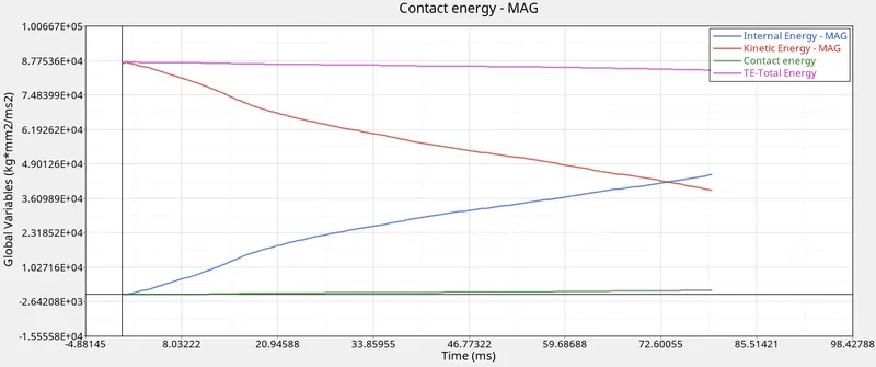
3) The total energy, kinetic and contact energy experienced by the model is depicted the output graph shown below;
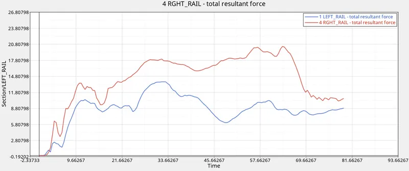
4) The axial forces on the rails by the bumper is as shown in the graph below
5) The intrusions at the dash wall at the nodes 66695 and 66244 is as following depicted in the outout graph.
6) The forces experienced by shotgun, b-pillars is as follows;
7) Acceleration curve for the 2 accelerometers present at the base of b-pillars is as follows
CONCLUSIONS:
- As we observe from the .out file, the errors are in acceptable range so the simulation is acceptable.
- The von mises stresses show that the maximum stress concentration occurs at the front of the vehicle which is the expected result for any car crash scenario.
- As kinetic energy decreases, internal energy increases. Total energy is almost constant but due to some energy error it gets decreased.Due to some friction defined in type 7 contact there is some contact energy generated.
- In each of the cross setions, the right section experiences more force than the left section which indicates that the crash was not exactly perpendicular to the wall or the left section is weaker.
- The accelerometer added at the base of pillar depicts the acceleration after the impact. The acceleration isn't constant after the impact. The spike in acceleration depicts some failure of component occuring after the impact.
- The displacement of node 66244 is significantly more than that of 66695. This tells us that the rails absorb some of the forces which results in lesser deformation for 66695. As lesser support is available near acceleration padel more deformation surrounding it.
LEARNING OUTCOME:
- Learnt how to setup a frontal crash simulation
- Interpretation of the results based on simulation.
- Importance of mass balancing.
NOTE: Download all the rar files and then extract. The rar files are split for uploading the files as the file sizes were too large.