Assignment 6-Frontal Crash Simulation Challenge
Objective:
To perform a frontal crash with the help of a given car model. To obtain the results as mentioned in the above question, the following steps should be followed
- Check unit system and either follow[Mg mm s] or [Kg mm ms].
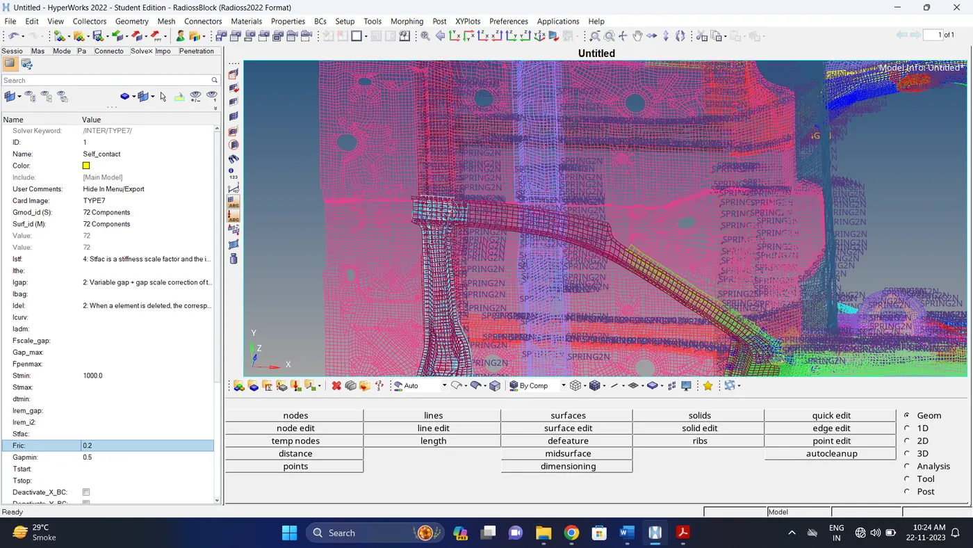
- Create appropriate interface ,friction 0.2 and recommended parameters.
- Make sure of no penetrations and intersection.
- Correct rigid bodies if any issues.
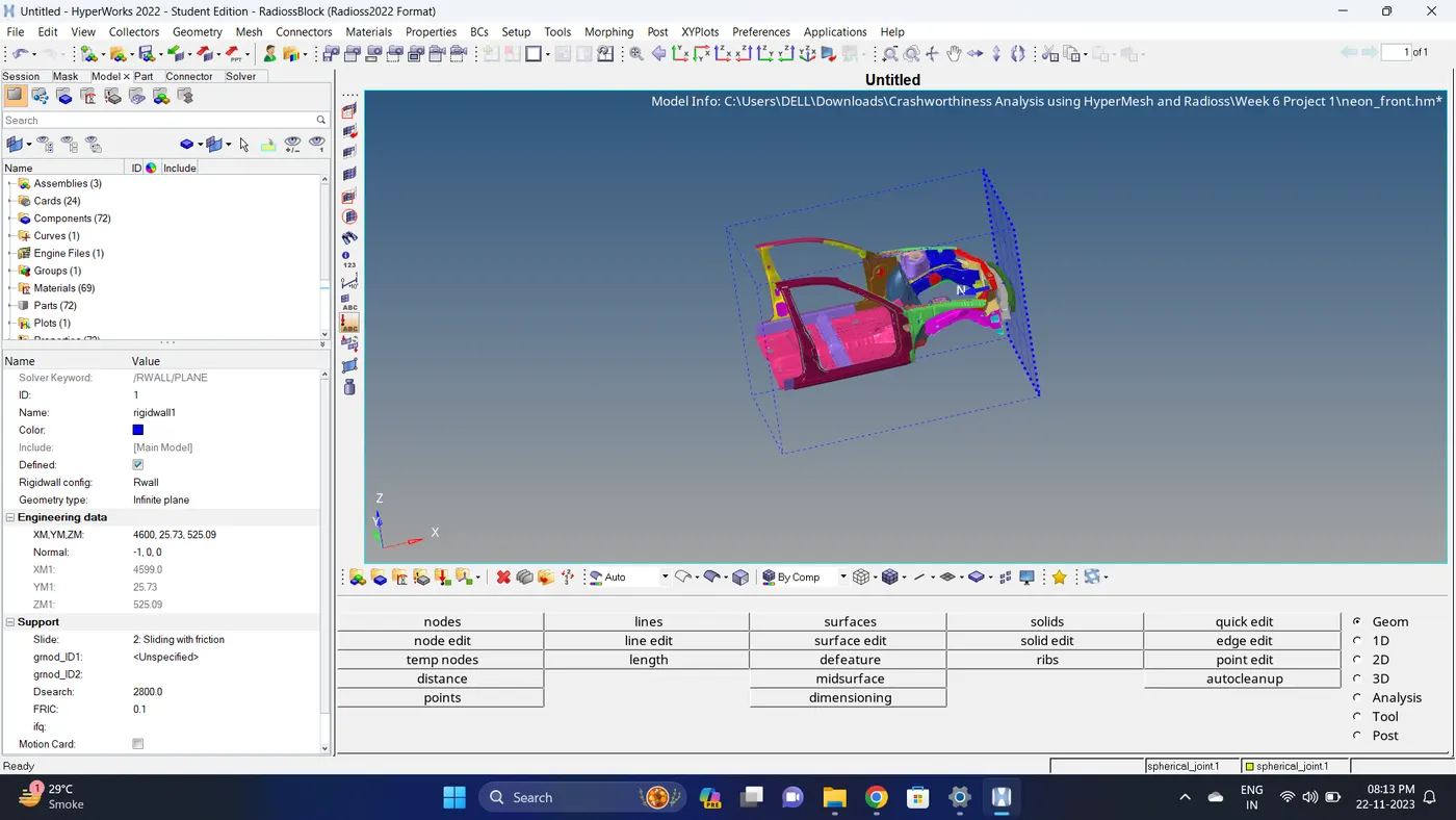
- Create rigid wall with friction 0.1.
- Compare the model weight with the full scale 300k nodes model and use added masses to reach target weight 700kg while getting CG about the required range.
- Initial velocity 35 mph.
- Use model checker to ensure good quality.
- Time-step :0.5 to 0.1 microseconds.
- Run 80 ms.
Output requests
- Sectional force in the rails at location of indicated node 174247.
- Axial force received on the rails from bumper.
- Shotgun cross sectional forces.
- A pillar cross section.
- Acceleration curve received on the accelerometer at base of B pillar (on B pillar rocker).
- Intrusions on the dash wall 66695,66244.
Procedure:
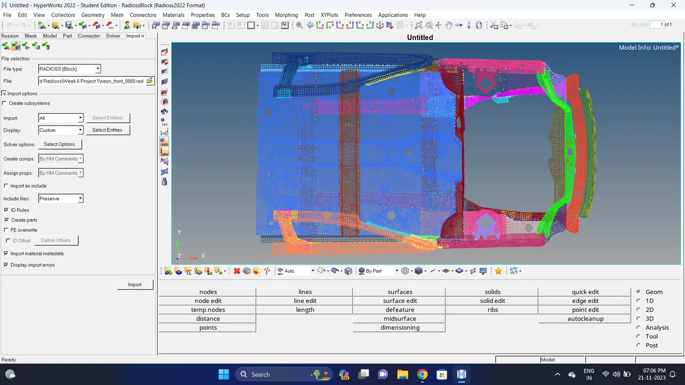
1. Import the neon_front_0000.rad file.
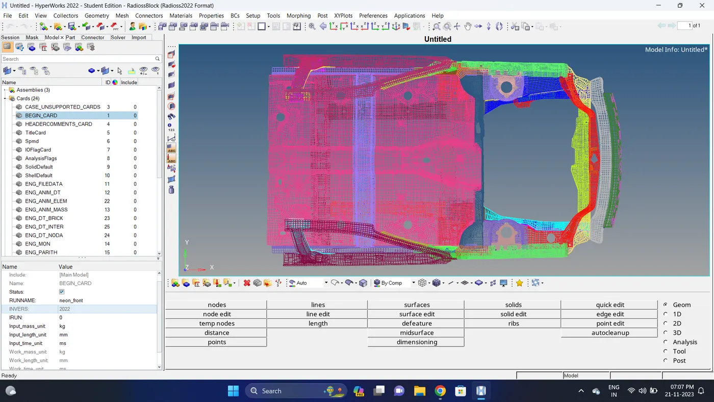
2. Go to Model deck - Cards - BEGIN_CARD and Check the unit system.
The unit system is kg - mm - ms.
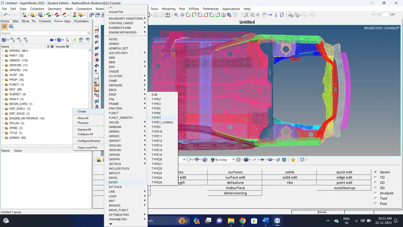
3. Create a TYPE7 self contact interface. Go to Solver deck - Create a new TYPE 7 INTER - Select nodes and elements - give parameters.
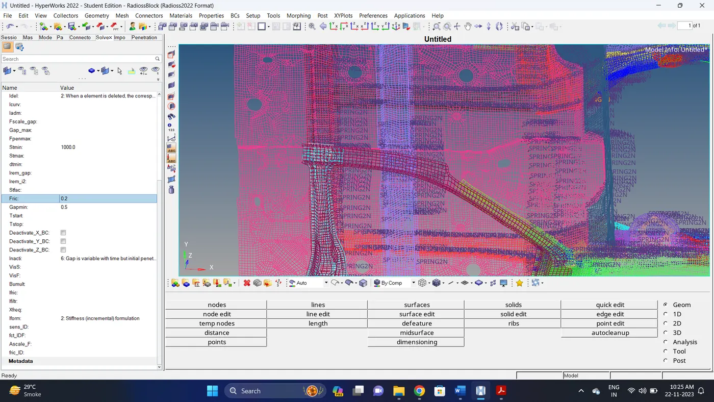
4. Check the intersections and penetrations.
Go to Tools - Penetrations Check - Select the components - Click on Check.
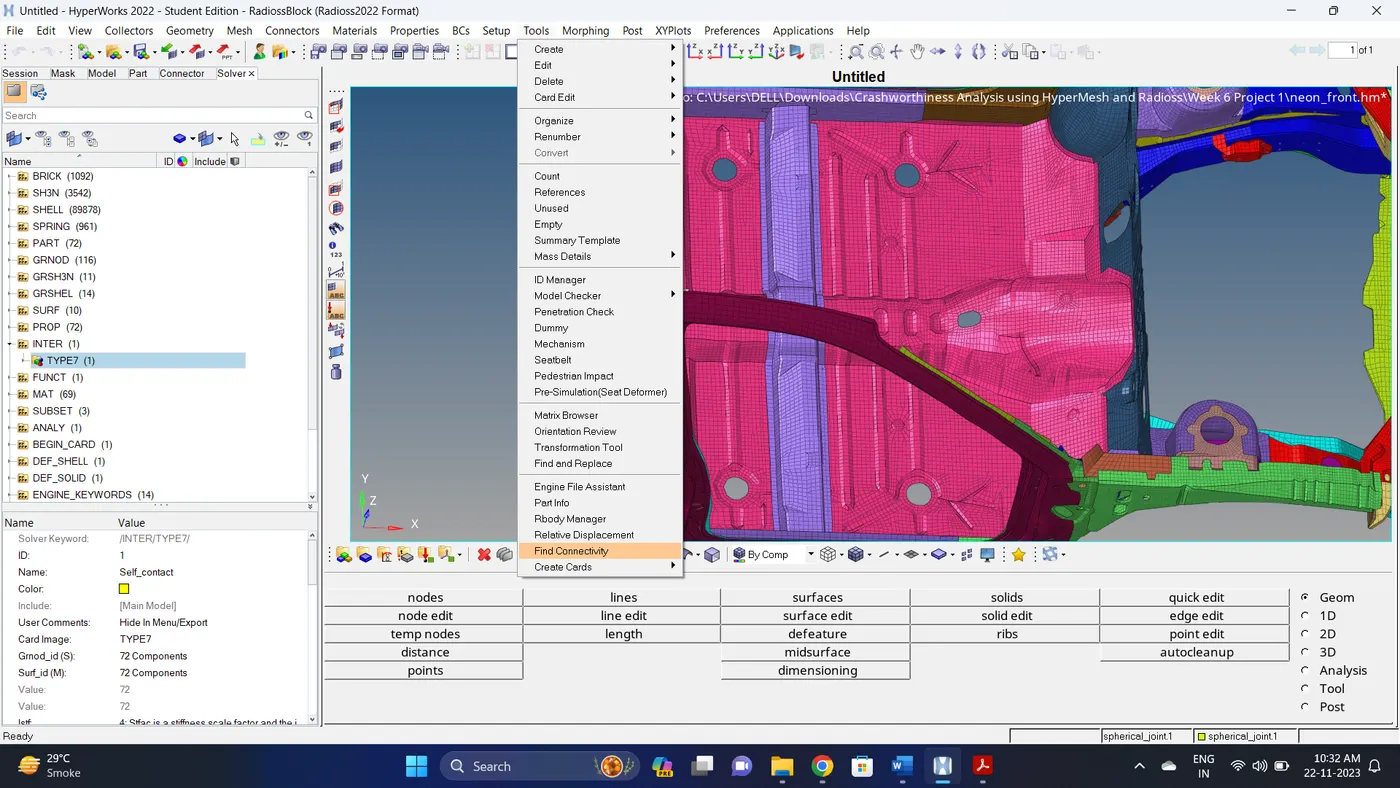
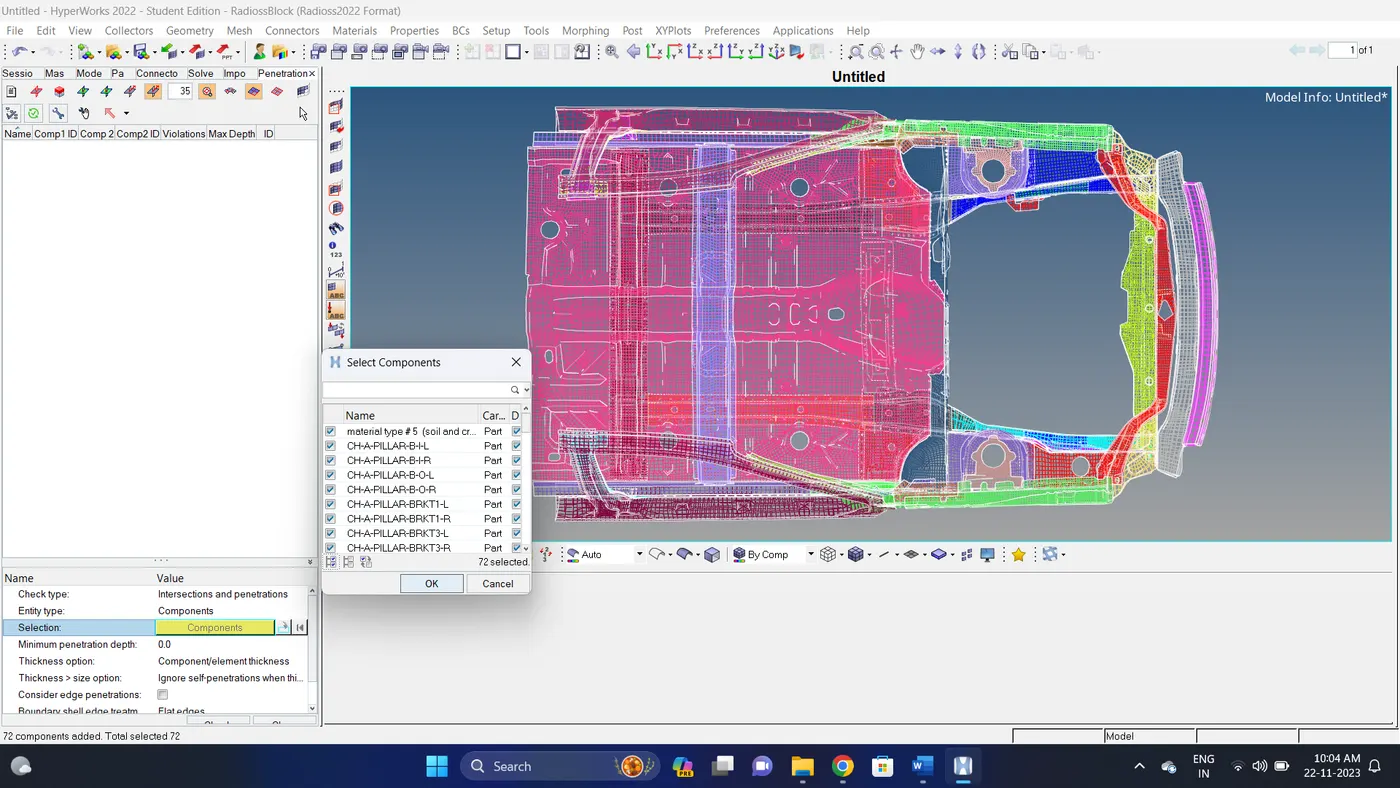
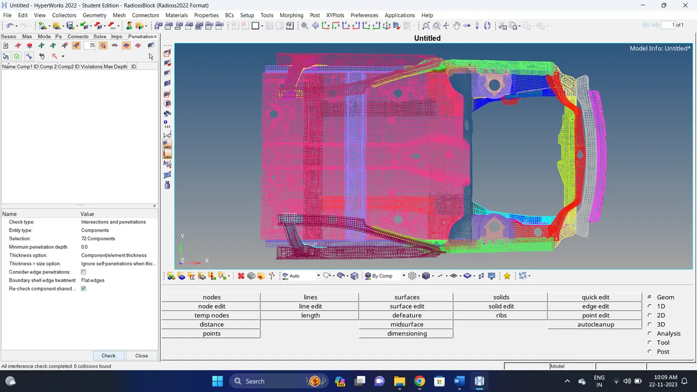
5. Create a RWALL.
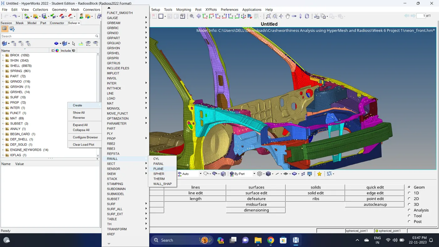
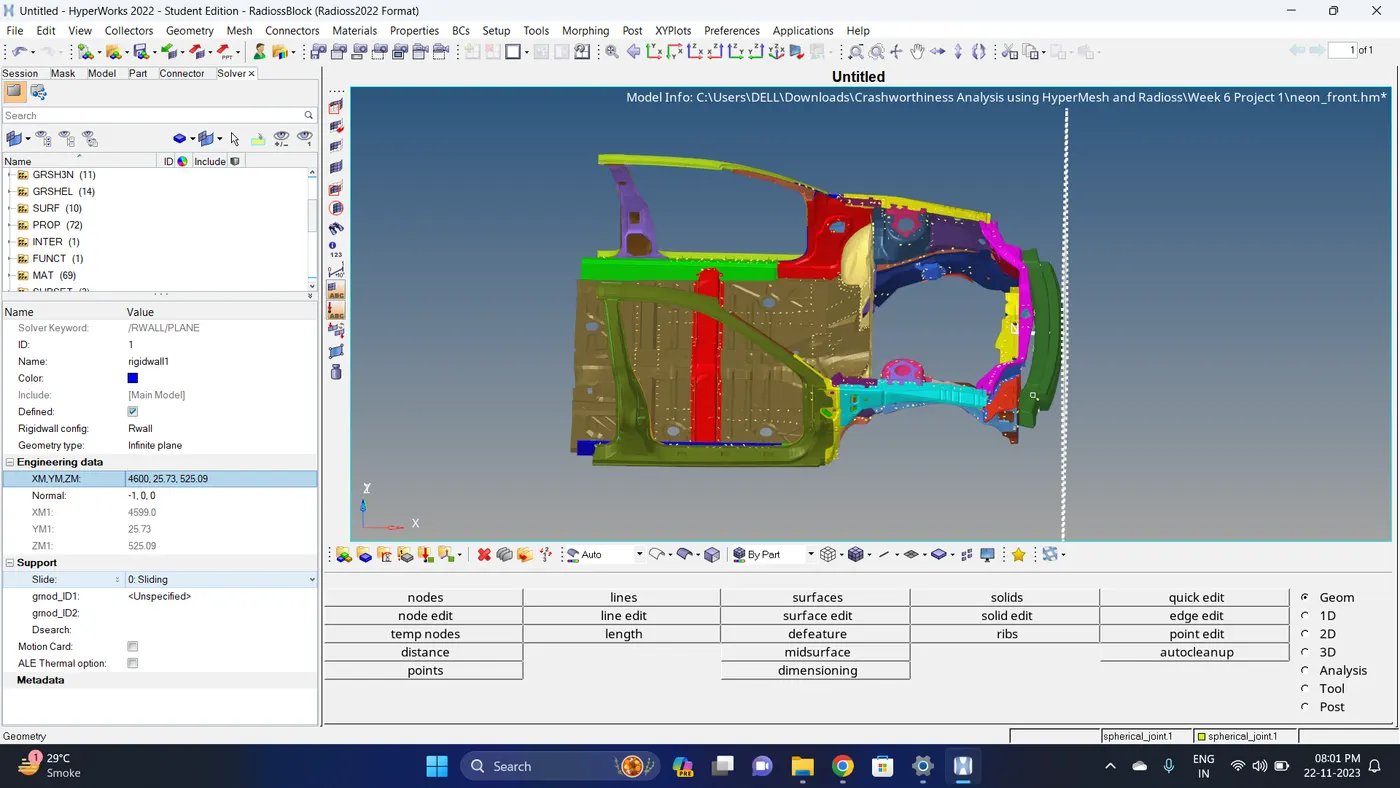
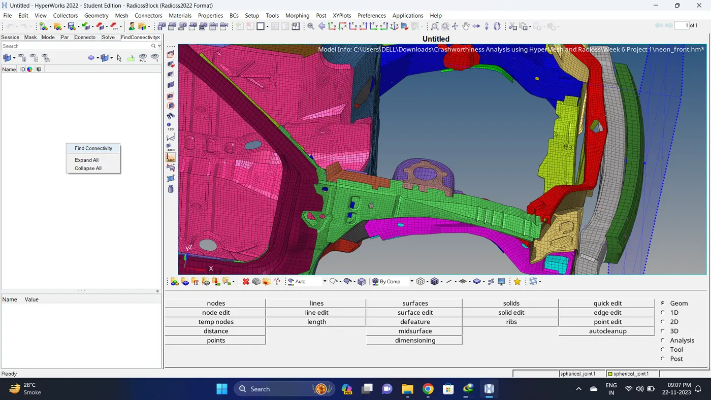
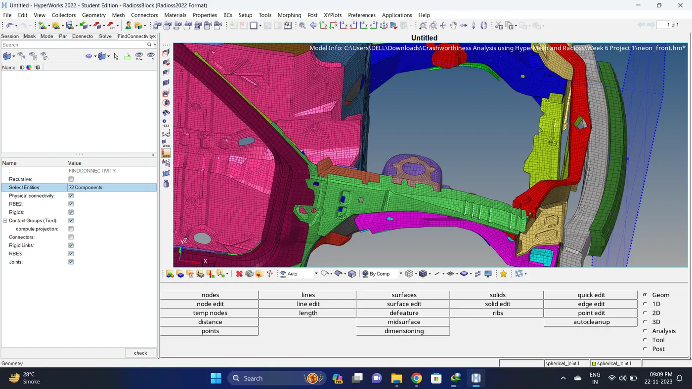
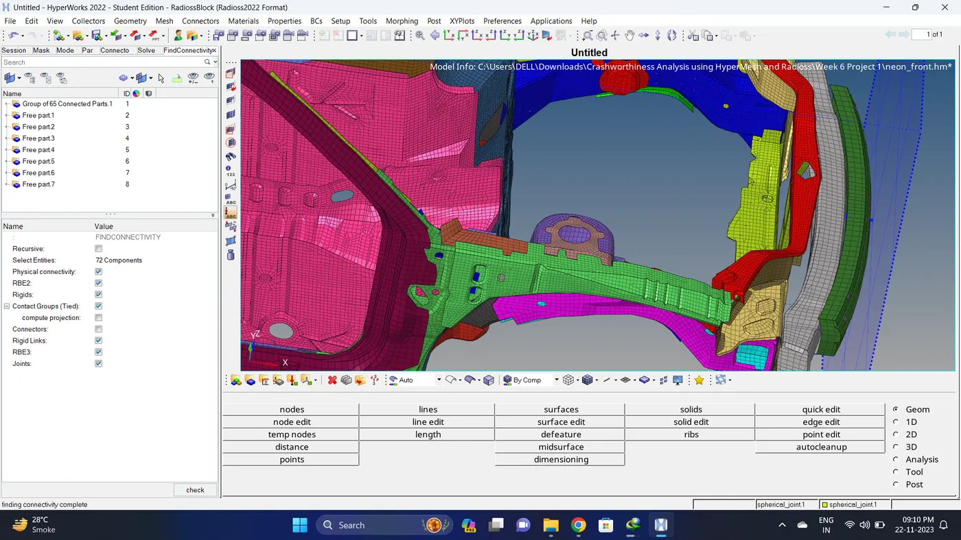
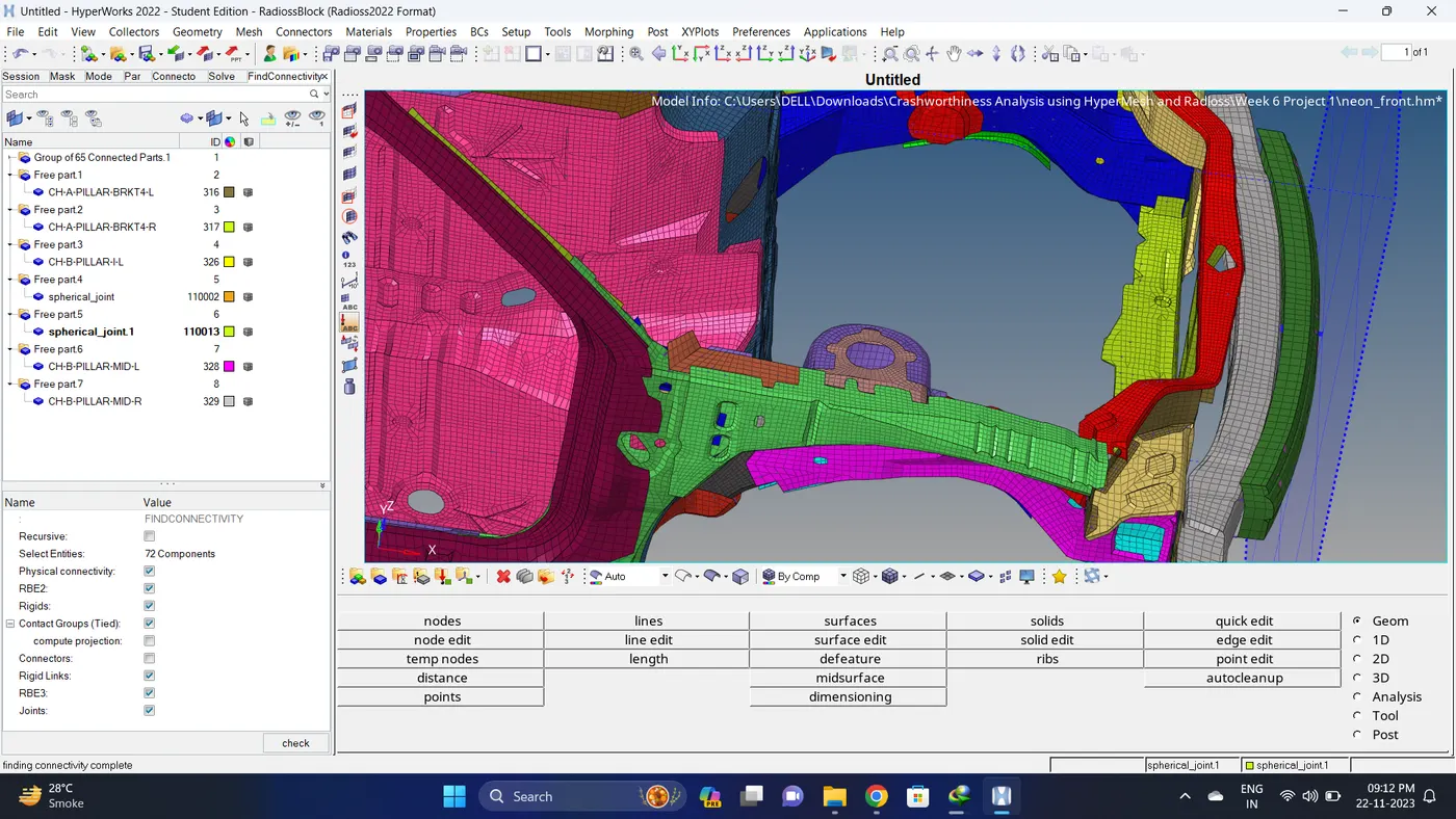
6. Find Connectivity of all the componnent. Go to Tool - Find Connectivity - Right click on blank deck - Click on Find Connectivity - Select all the component - Click on Check.
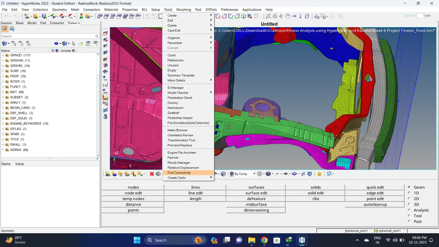
7. Make connection component card to current.
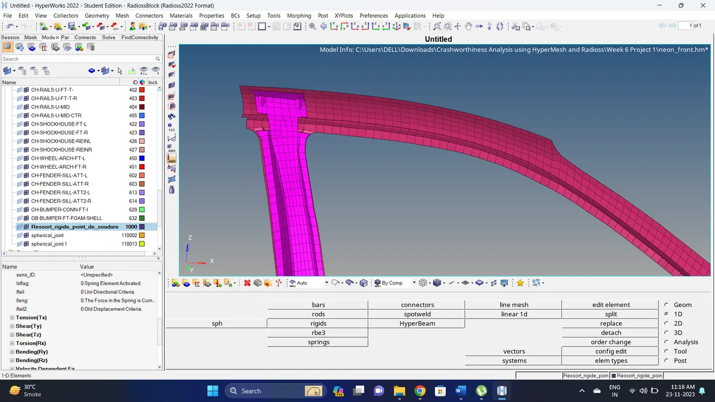
8. Firstly visible only the component which has to create a rigid connection. Go to 1D - rigids - select nodes and click on create.
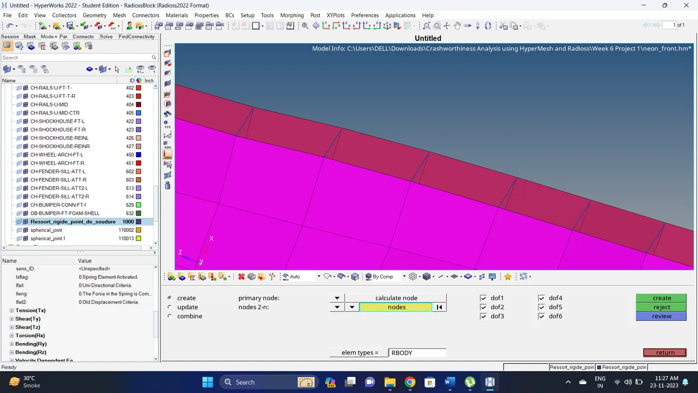
9. Do the same for all the other components also.
Note: In connnectivity dont consider Spherical joints.
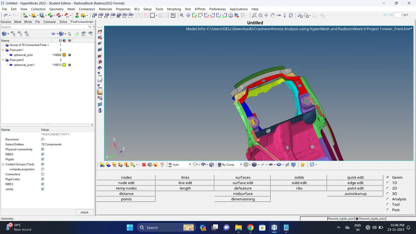
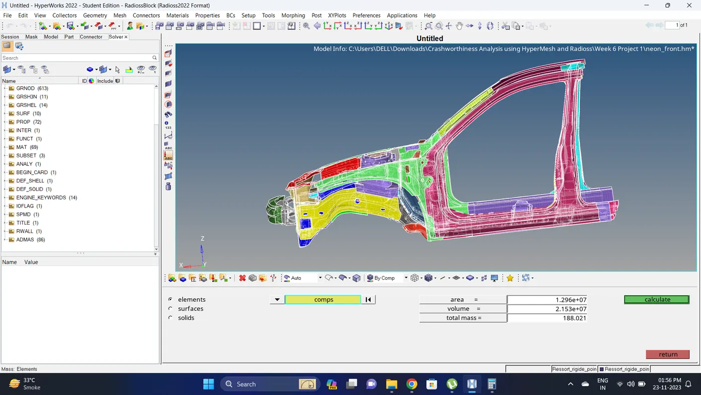
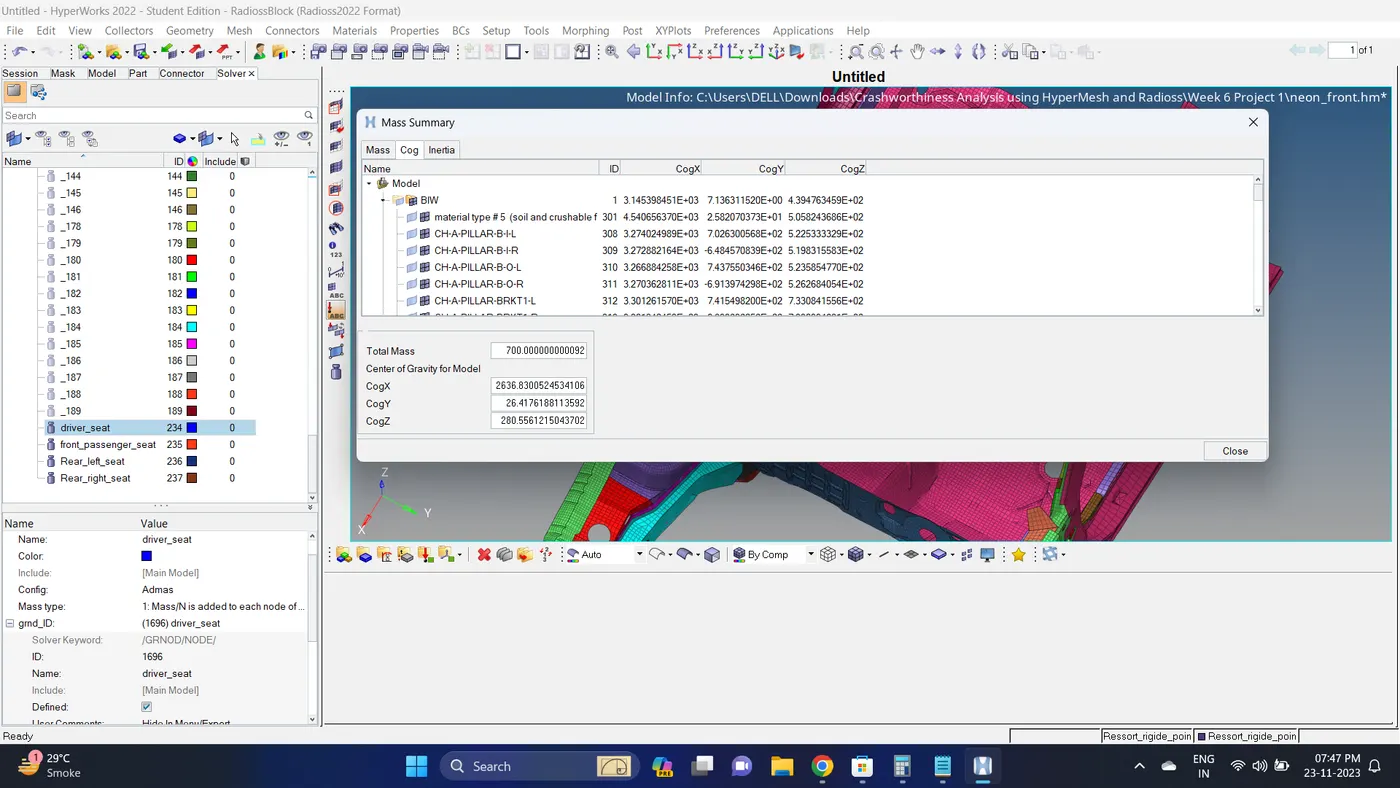
10. Add mass to the to get the COG of model correct and total mass of model should be 700 kg.Check the total mass of model and add mass accordingly.
To calculate mass go to tool - mass calc - select component - click calculate.
11. To create/add mass go to Solver deck - ADMAS - Create a new ADMAS - Change the mass type to 1 - In surface id right click and click click/edit - select nodes - Give mass value.
Note: add mass on the different region to get the COG correct and Total mass should be 700kg.
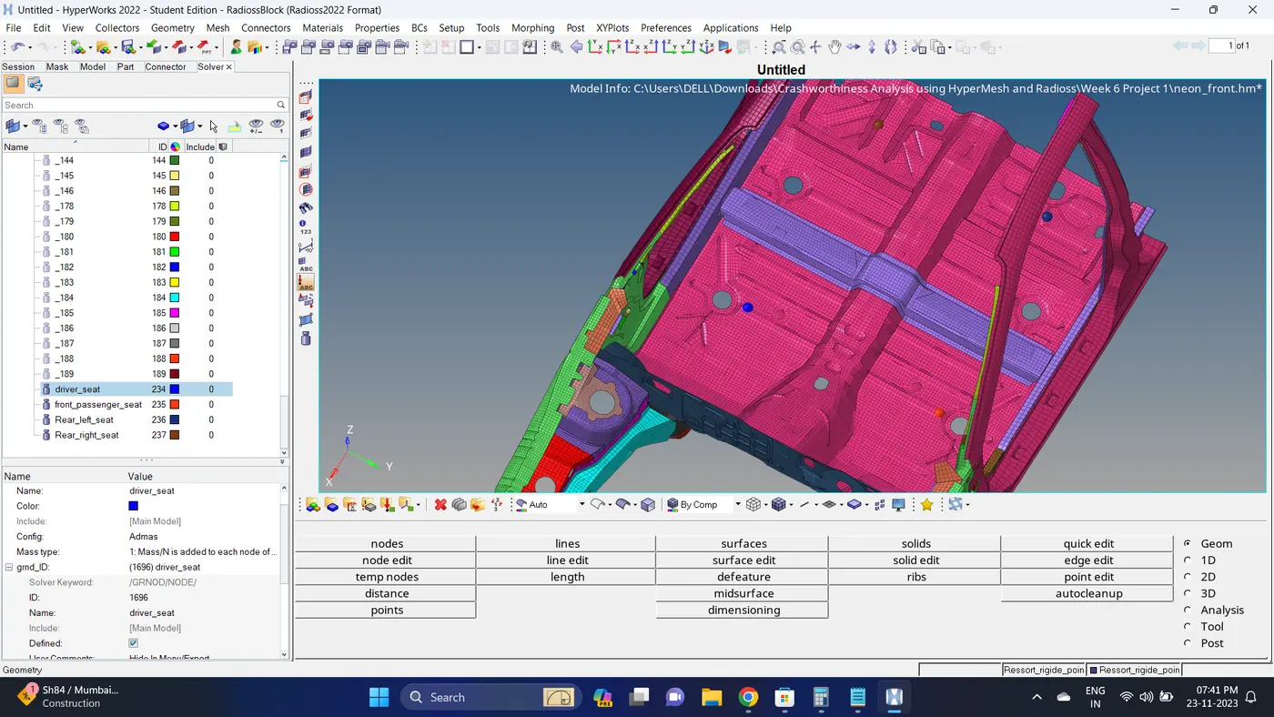
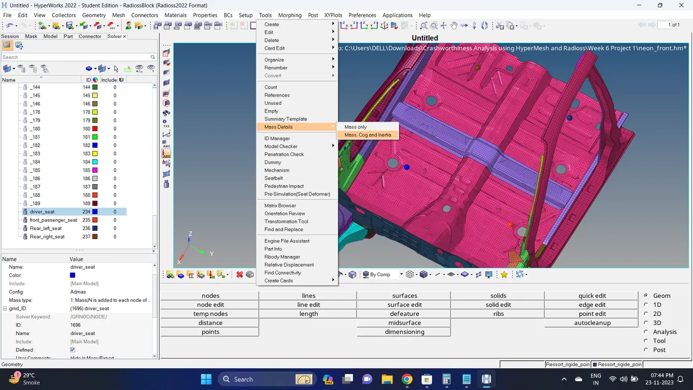
12. To check the Mass and COG go to Tools - Mass details - Mass, COG and Inertia.
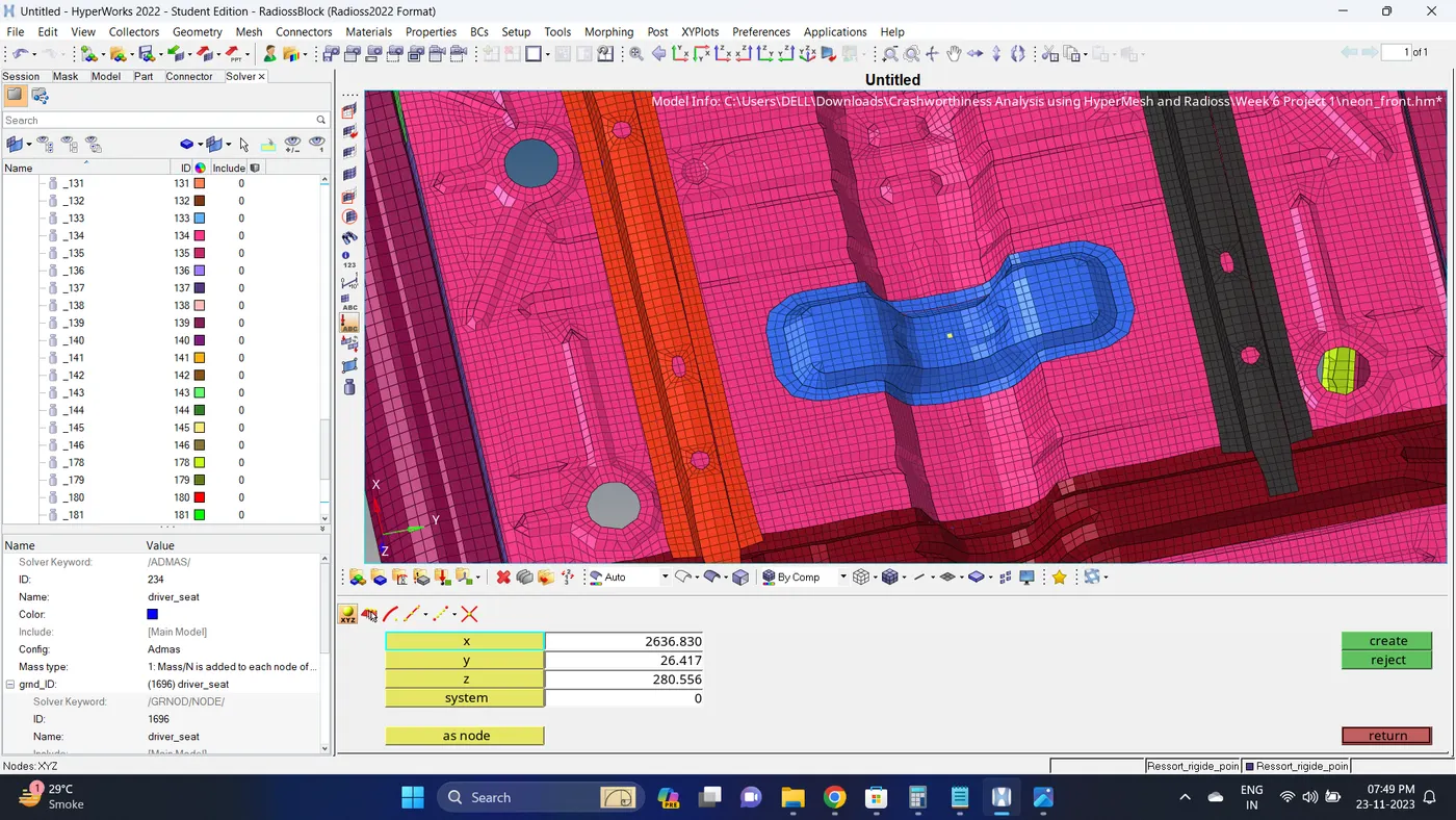
13. Note down the COG co-ordinates and create a node. Go to Geom - nodes - Insert the Co-ordinates and click create.
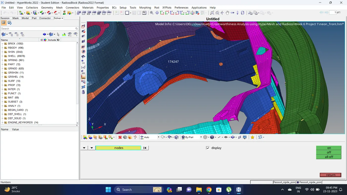
14. Displaying node 174247.
Go to Tools - numbers - by id - type node number - display on.
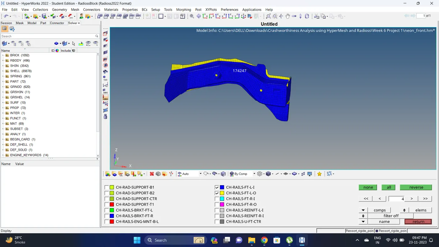
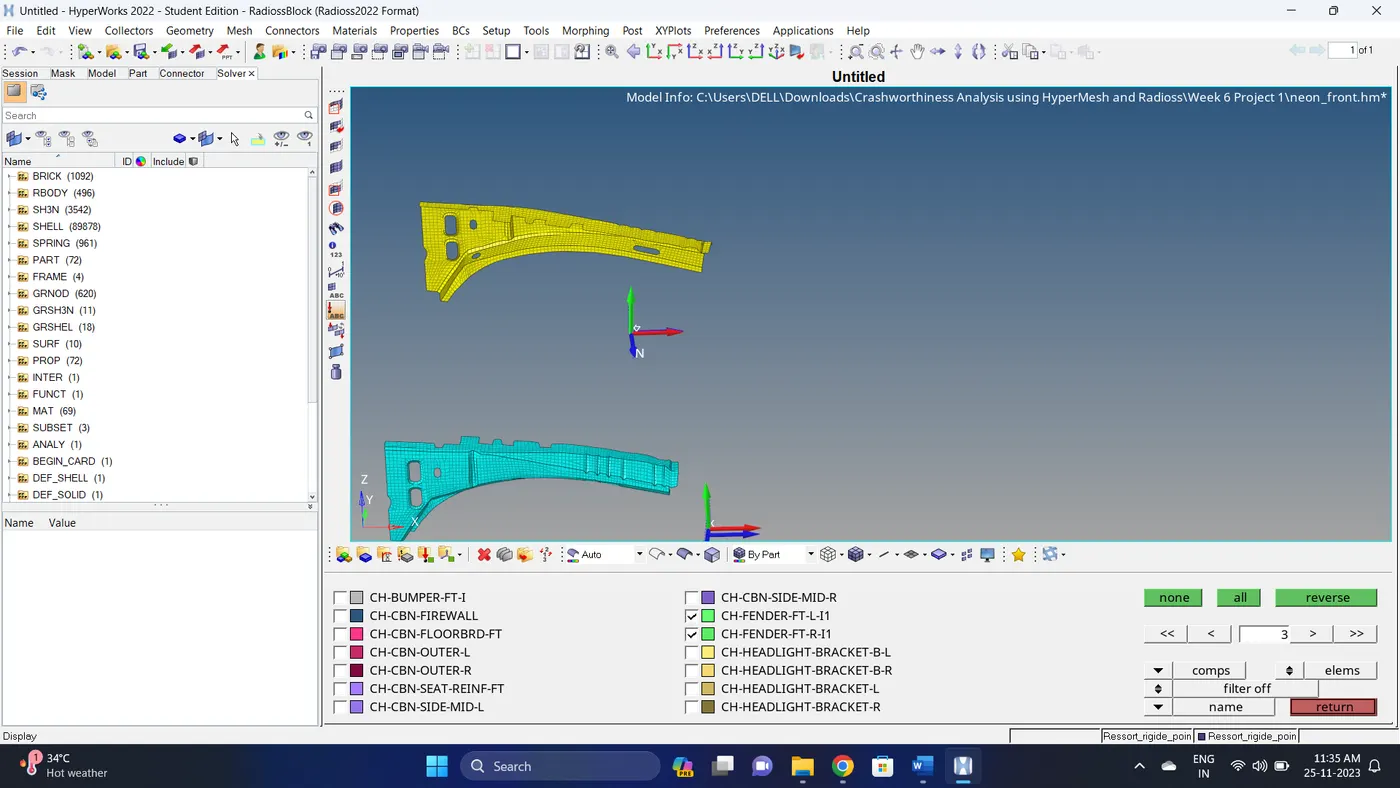
15. Isolate the component in which sectional force is to be calculated.
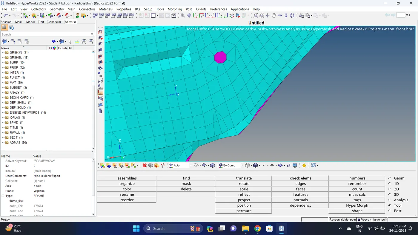
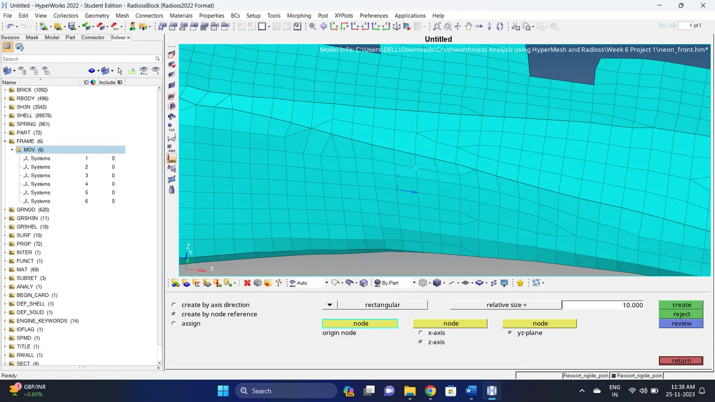
16. Create a moving frame. Go to the solver deck - right click - create - FRAME - MOV - Select the co-ordinate - click on Create.
Note: While creating the moving frame keep the Y-axis toward the crashing direction.

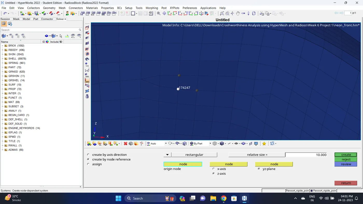
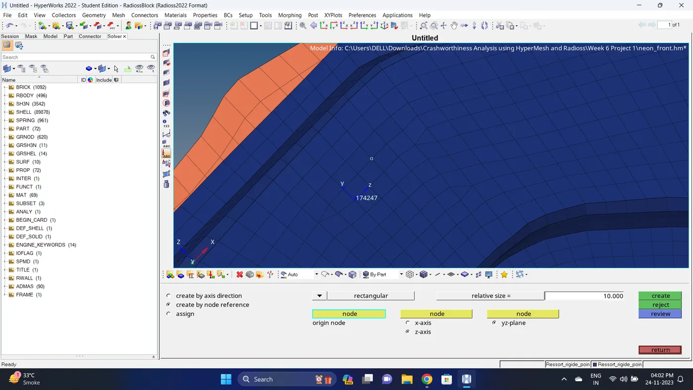
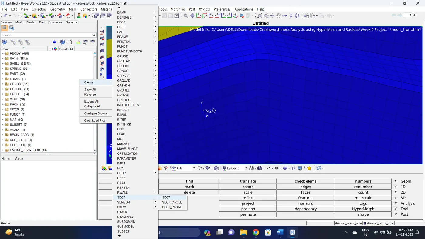
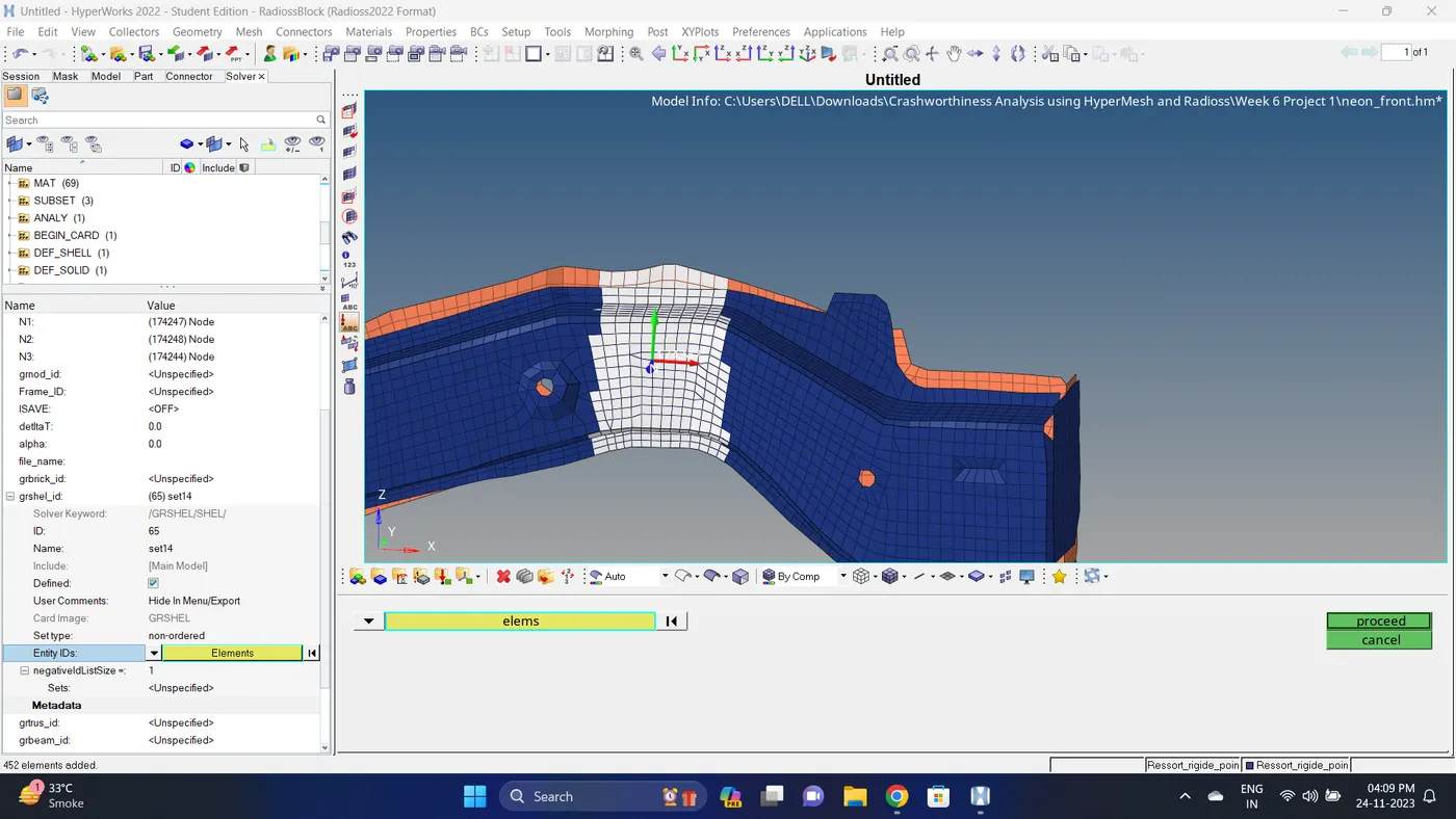
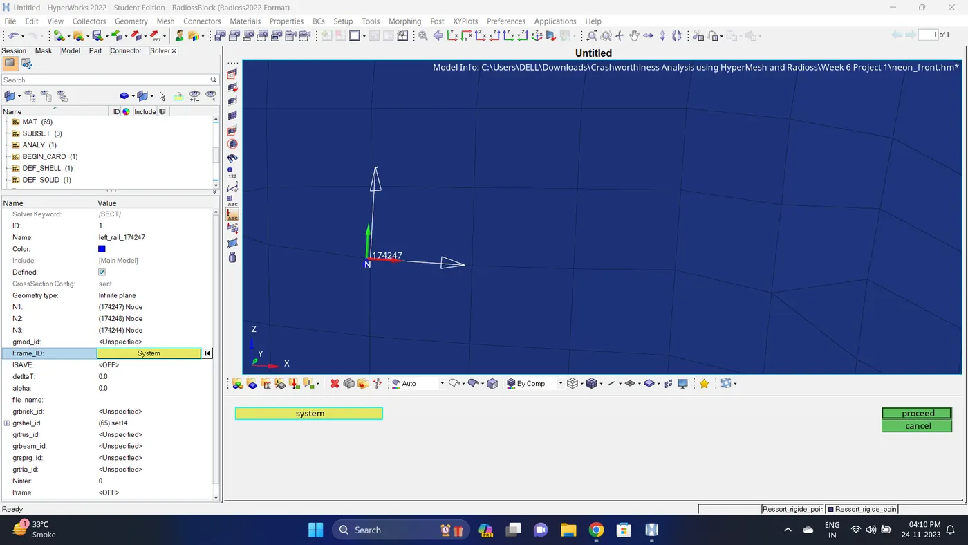
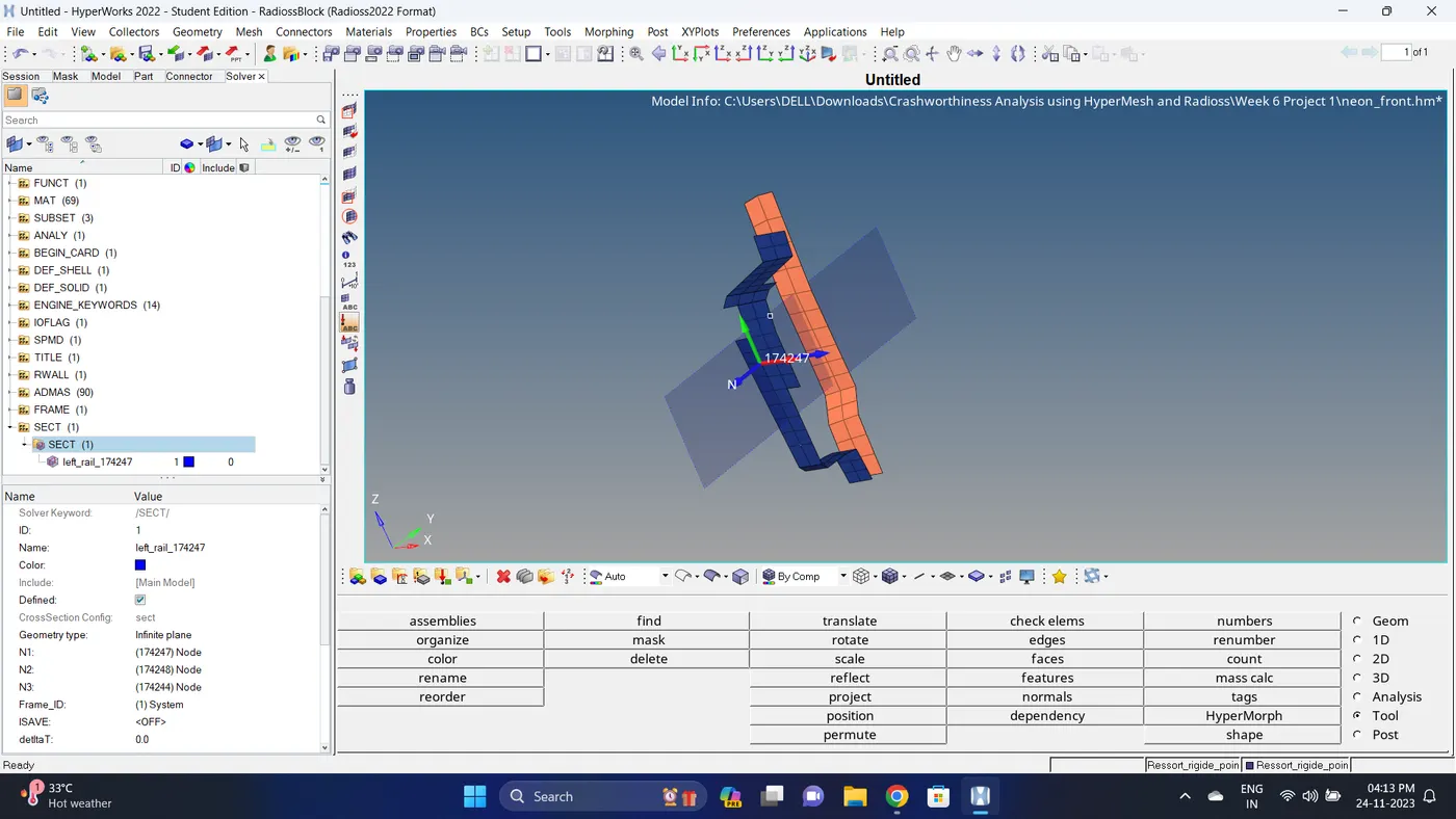
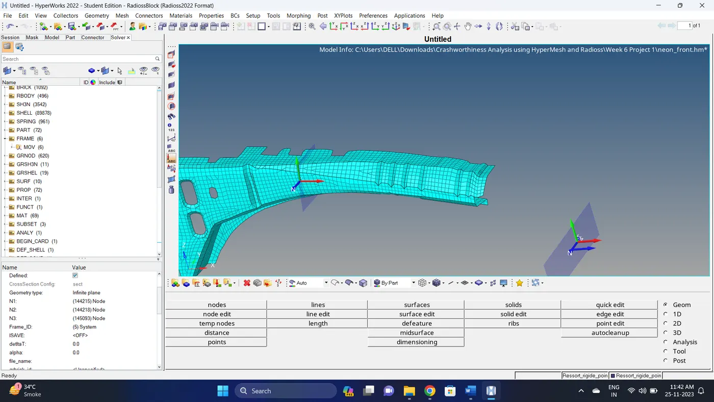
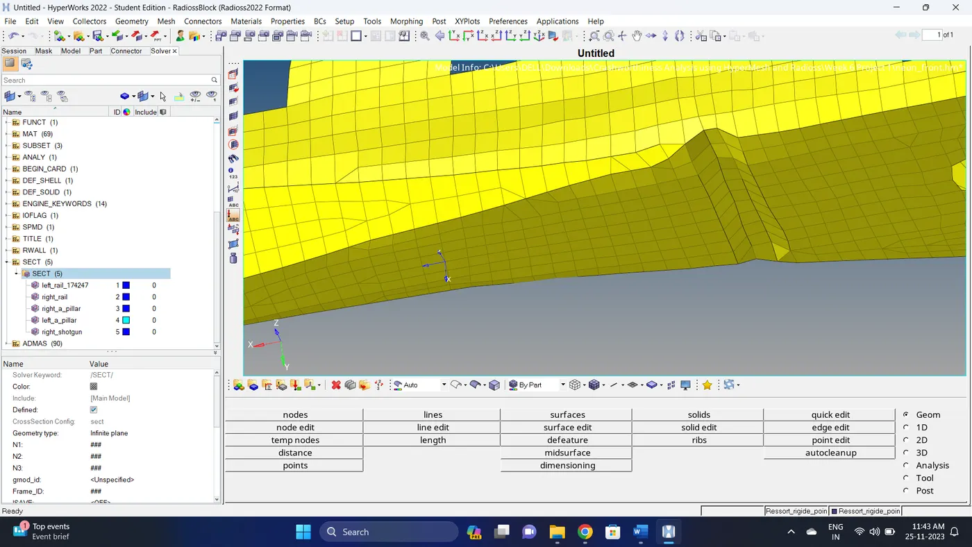
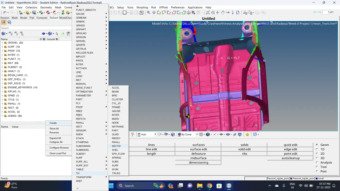
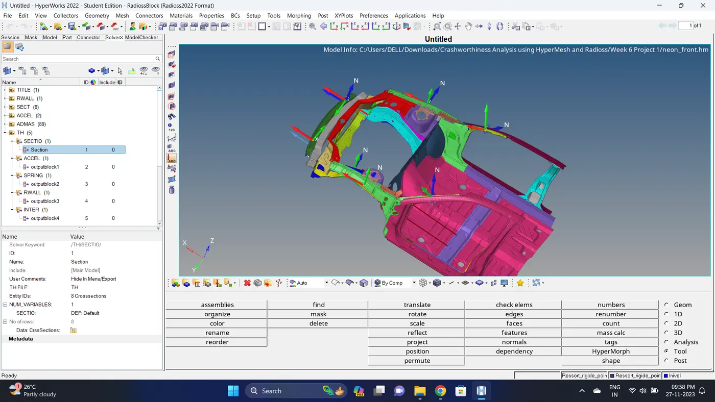
17. To create a section Go to Solver deck - Right click - Create - SECT - SECT - Change the name - Select N1, N2 and N3 Node - Select Shell group identifier element (grshel_id) - Select the Frame_id.
18. Similarly create the section on Right Rail.
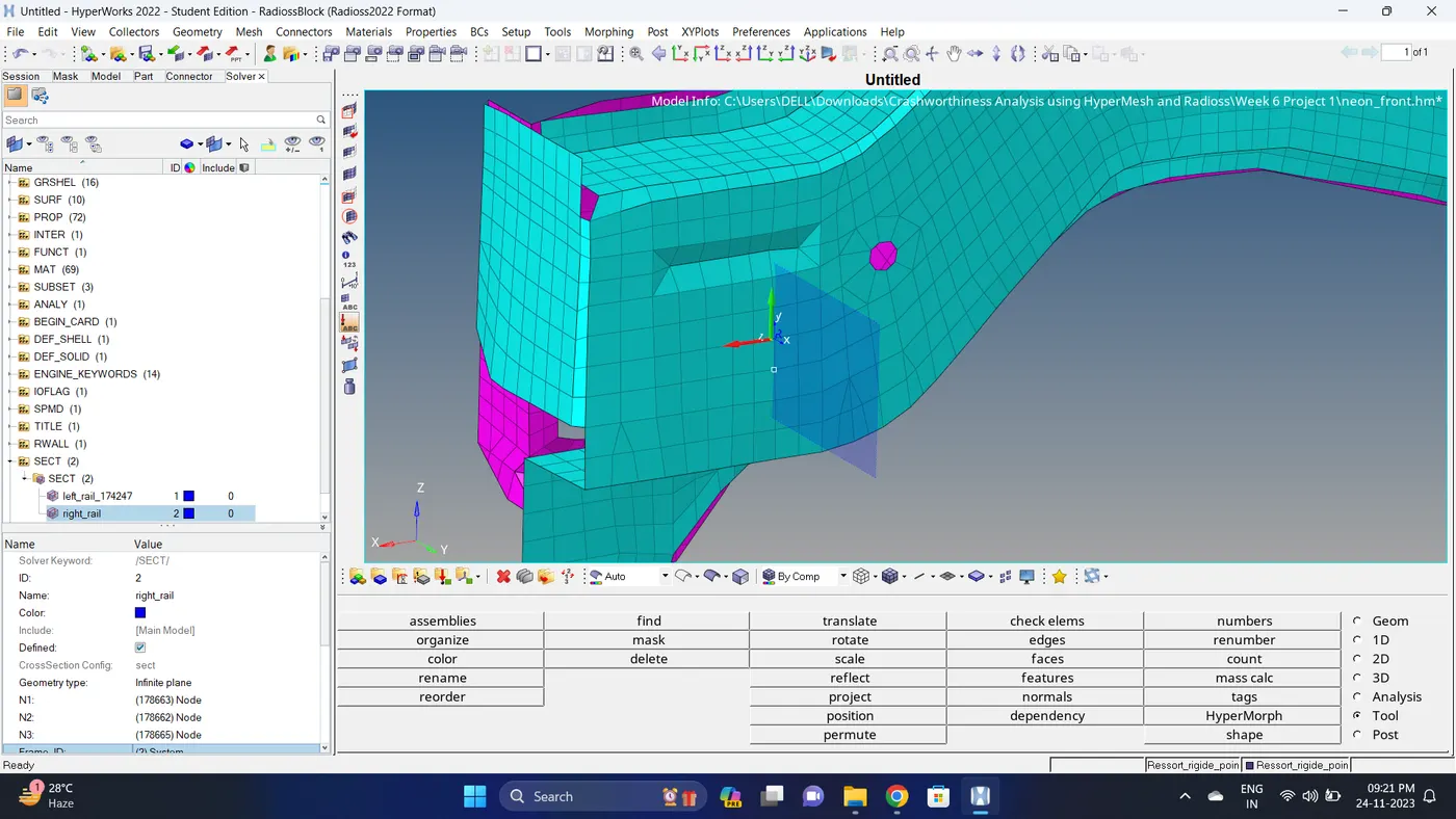
19. Similarly create a section on left and right A Pillars.
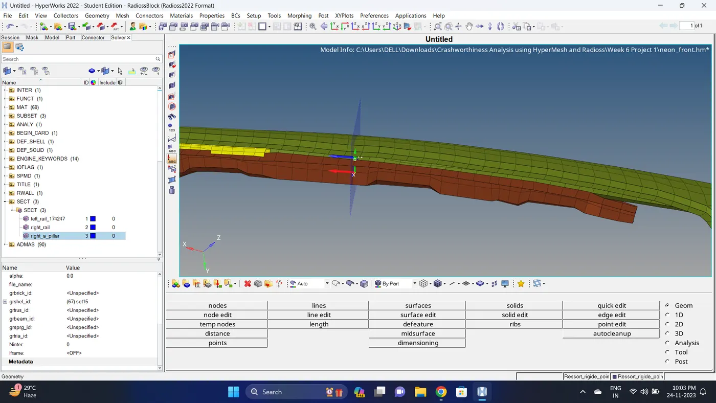
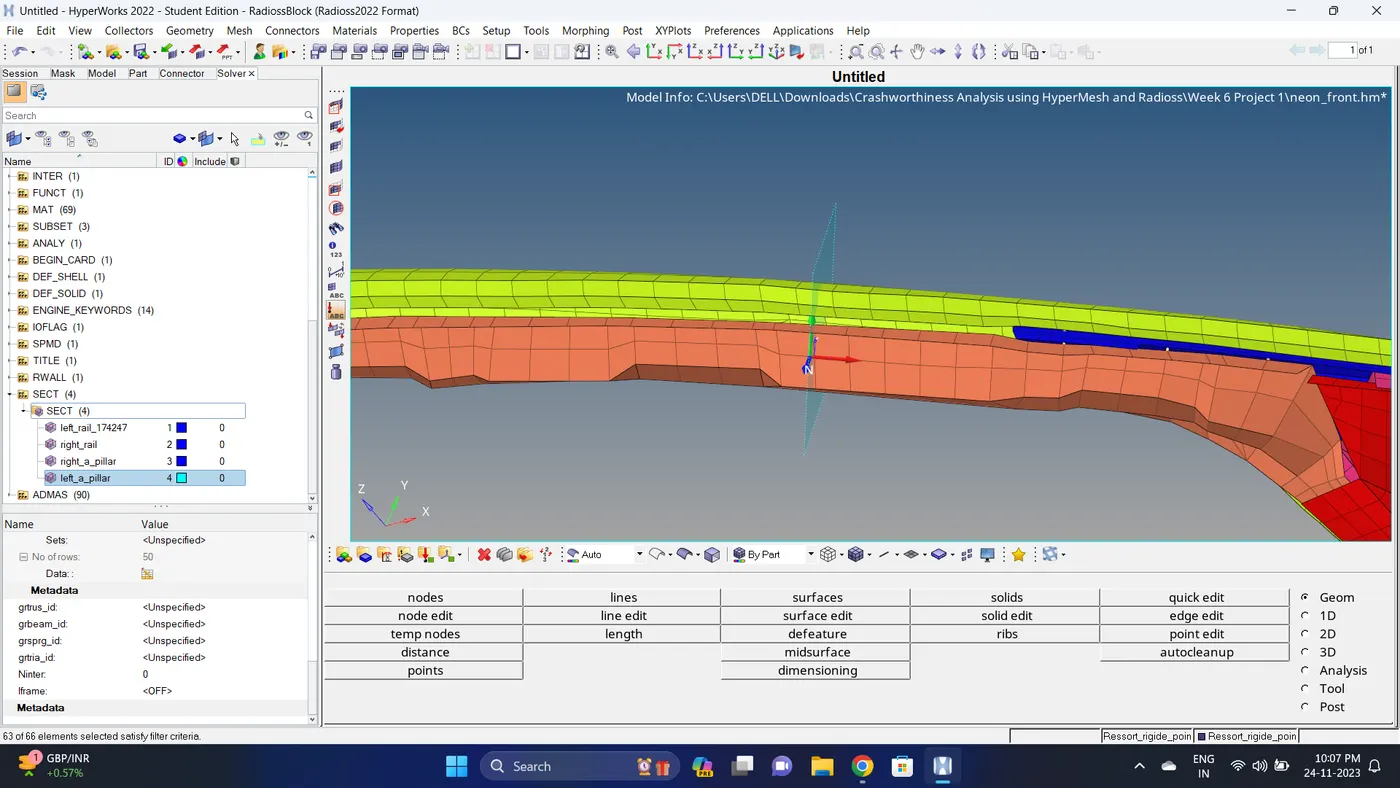
20. Similarly create a section on shotgun left and right (CH-FENDER-FT-L-I1 and CH-FENDER-FT-R-I1).
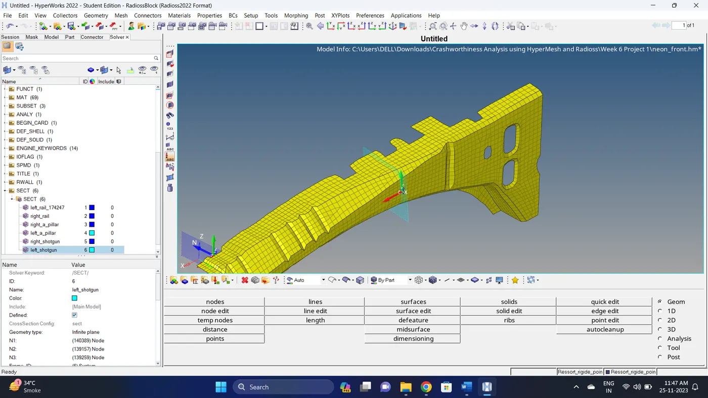
21. Similarly create a section on Bumper also.
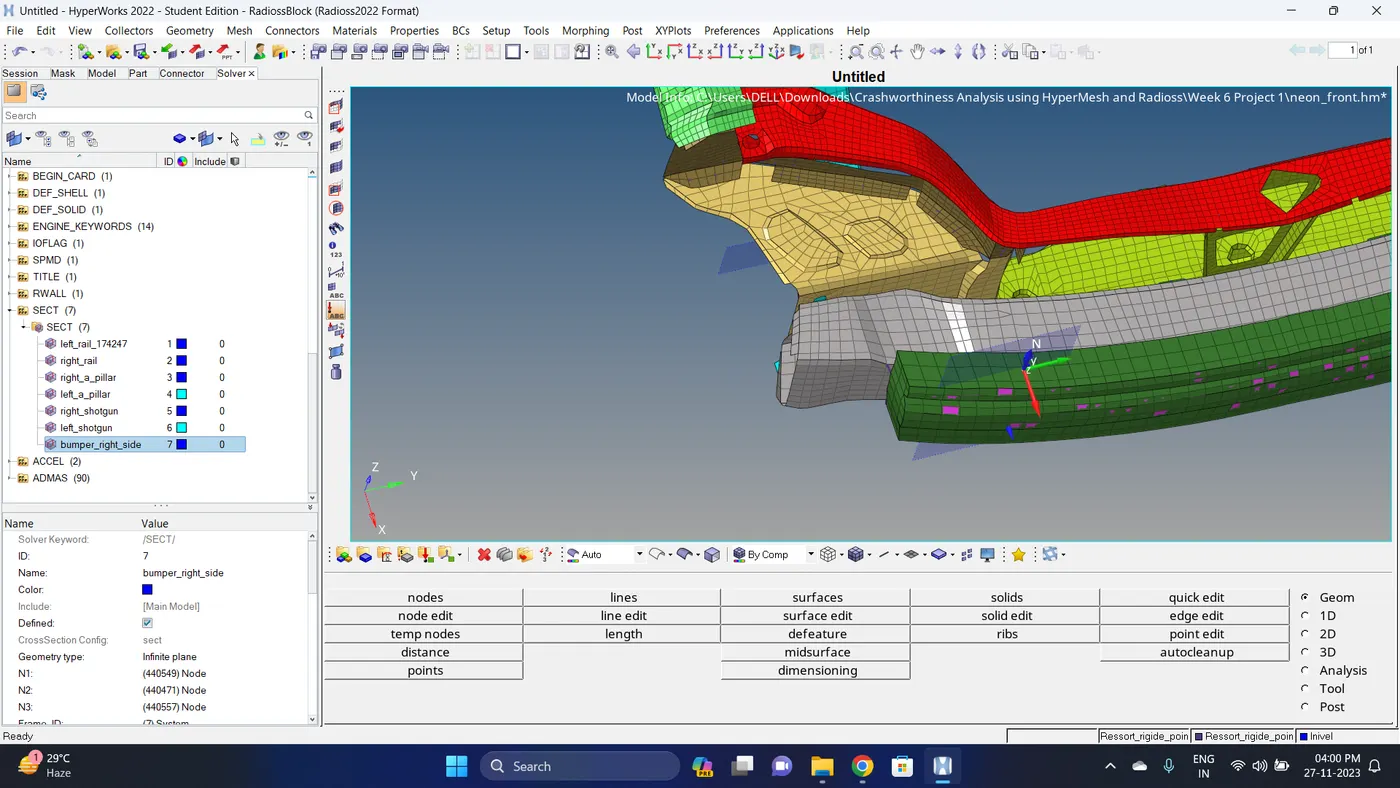
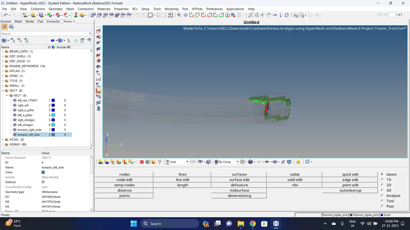
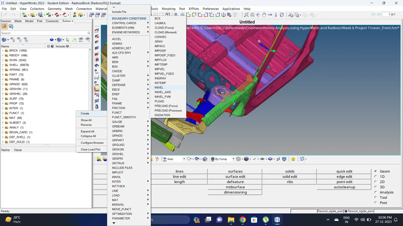
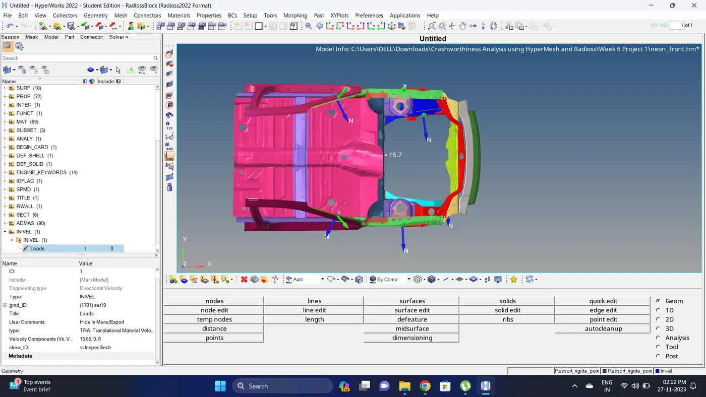
22. Create a Initial velocity. Go to Solver deck - Right click - BOUNDARY CONDITION - INIVEL - Give initial velocity - Create a new grnd_ID - Select nodes.
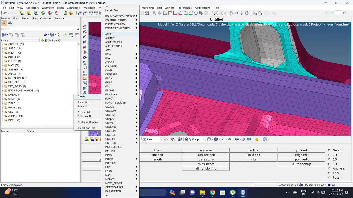
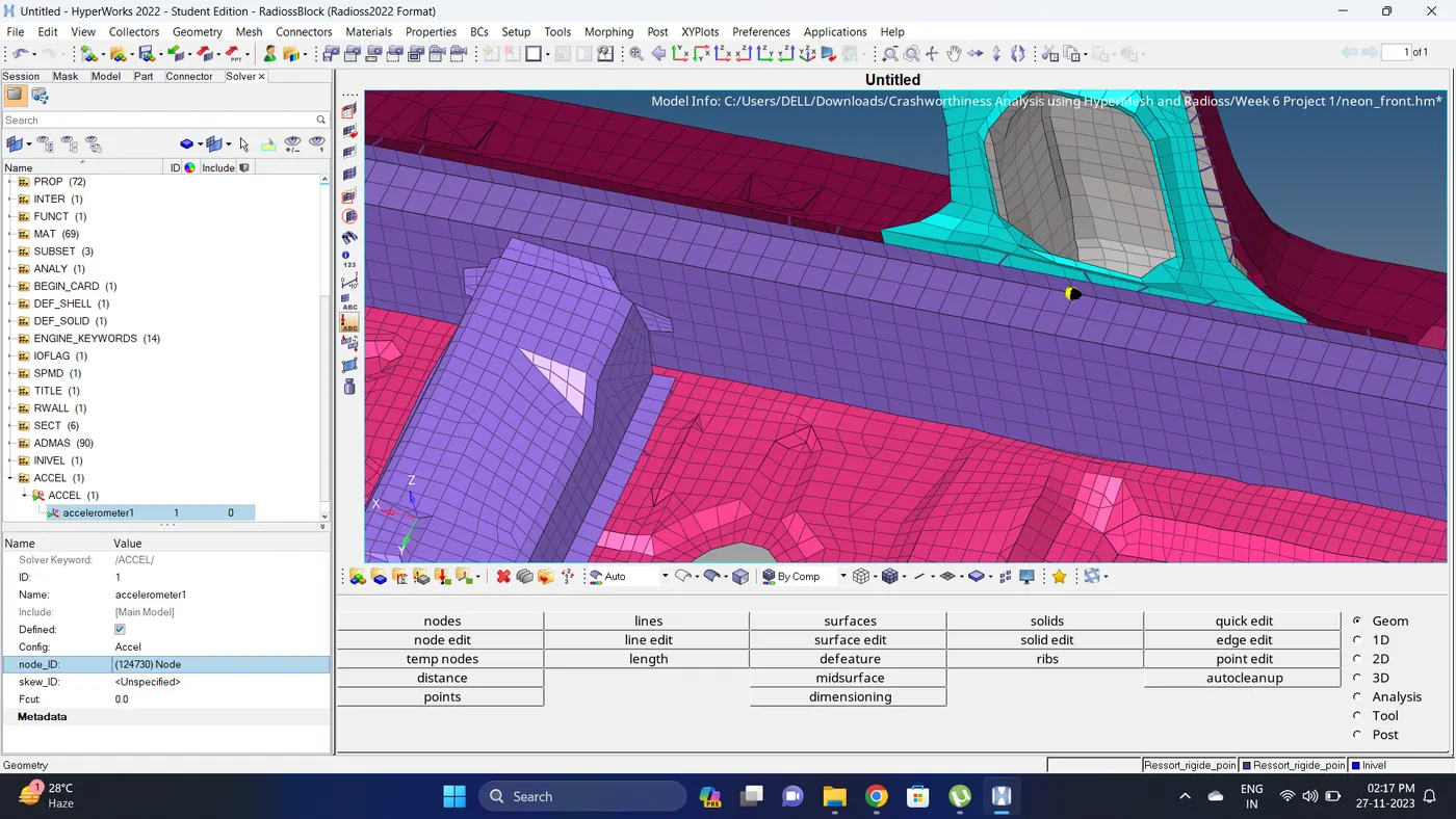
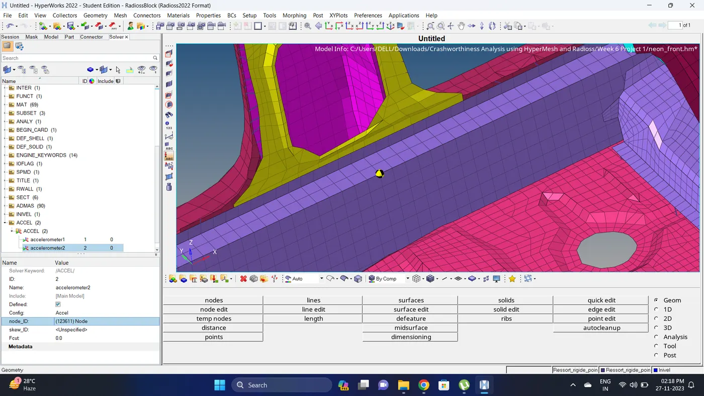
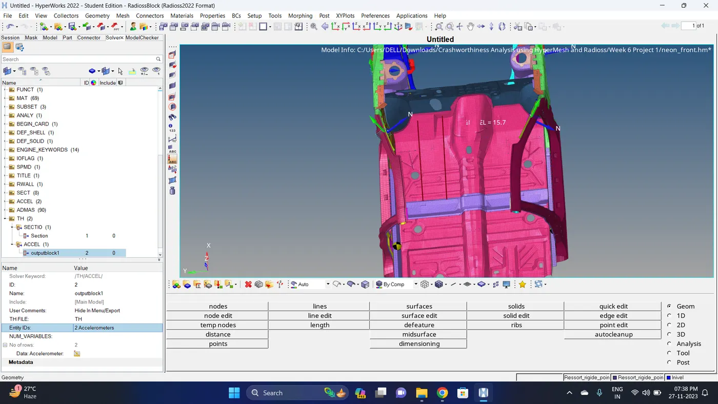
23. Create an the accelerometer at base of B pillar. Go to Solver deck - Right click - ACCEL - Select a node.
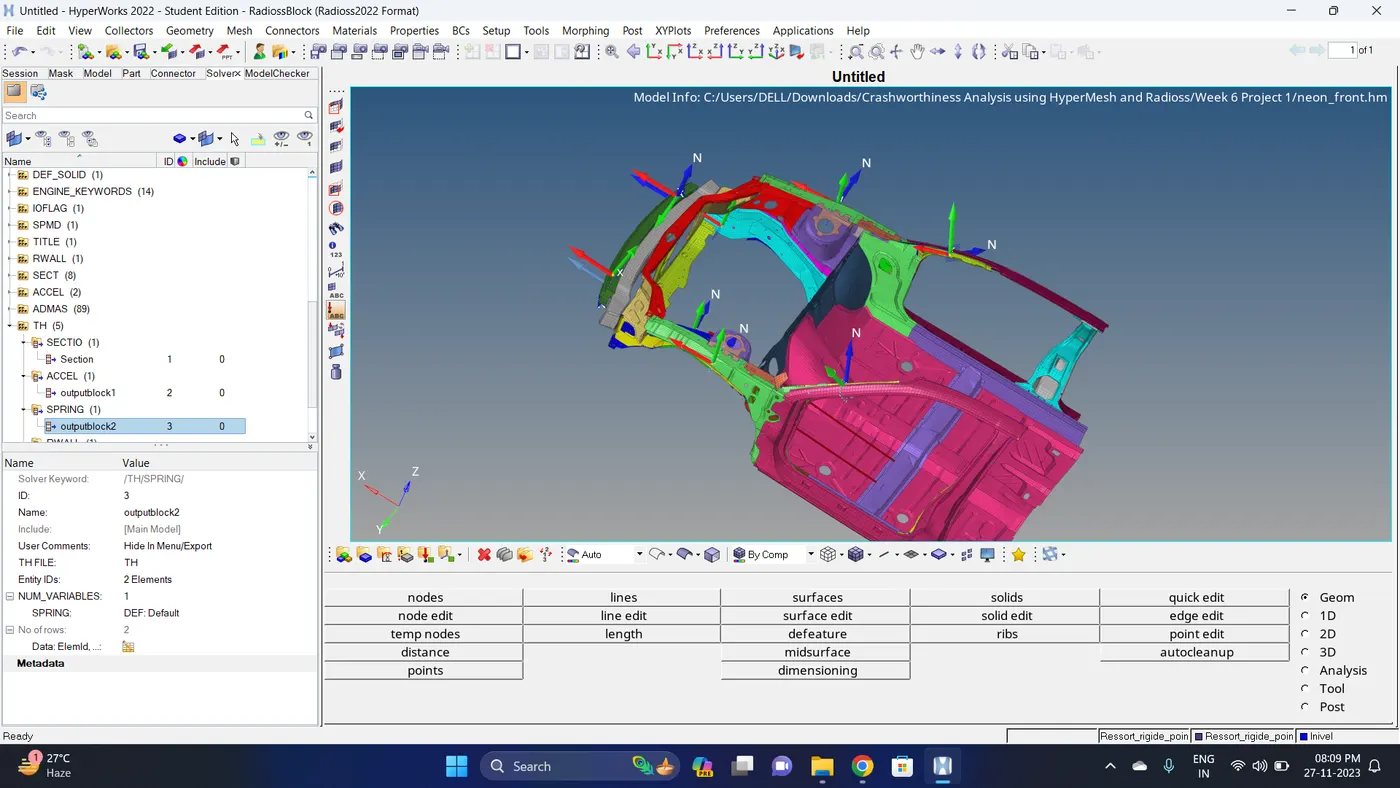
24. To create a Intrusions first create a new component - visible the node number - go to 1d - springs - select nodes (2 nodes should be on a straight) and create a spring.
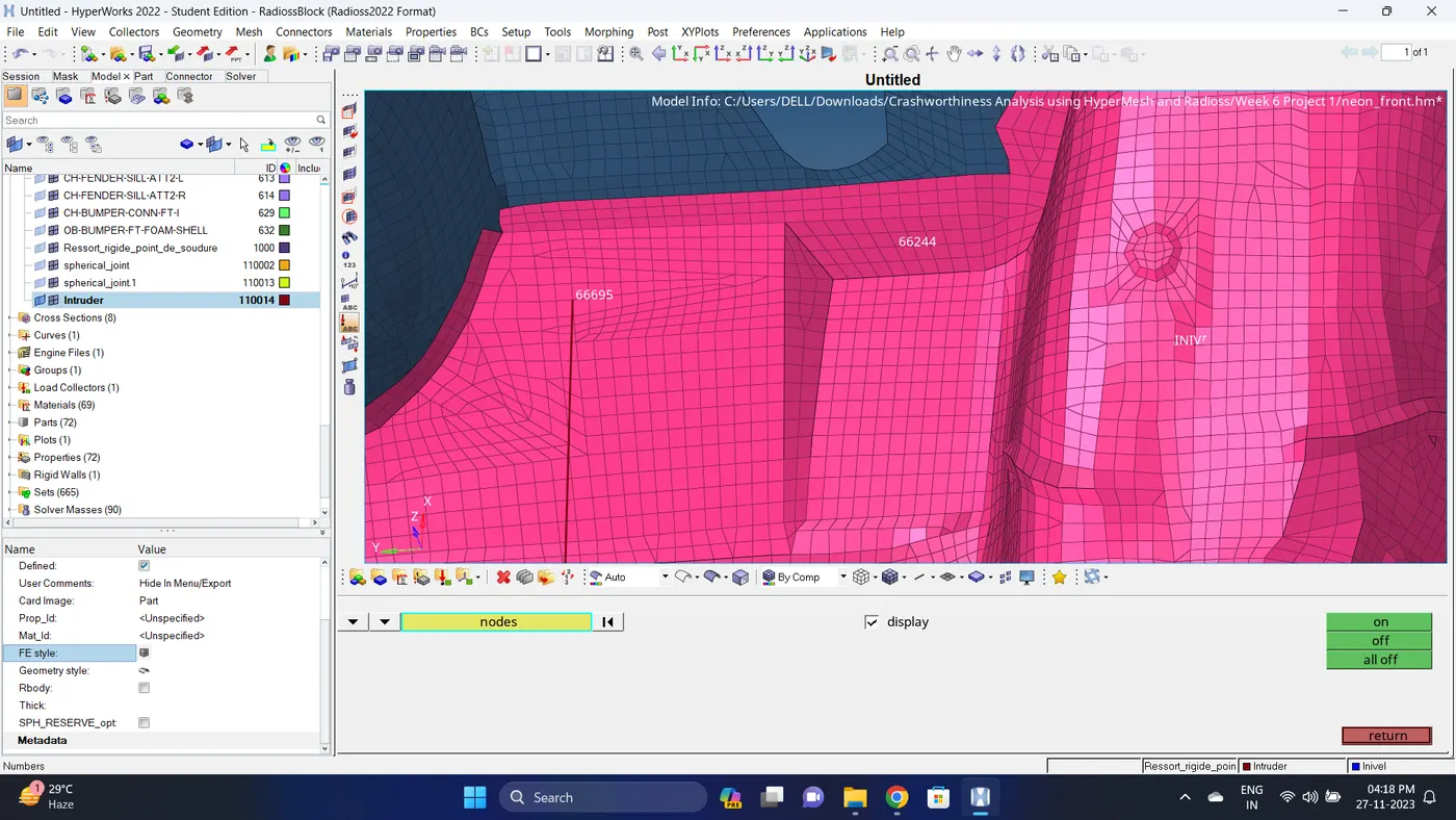
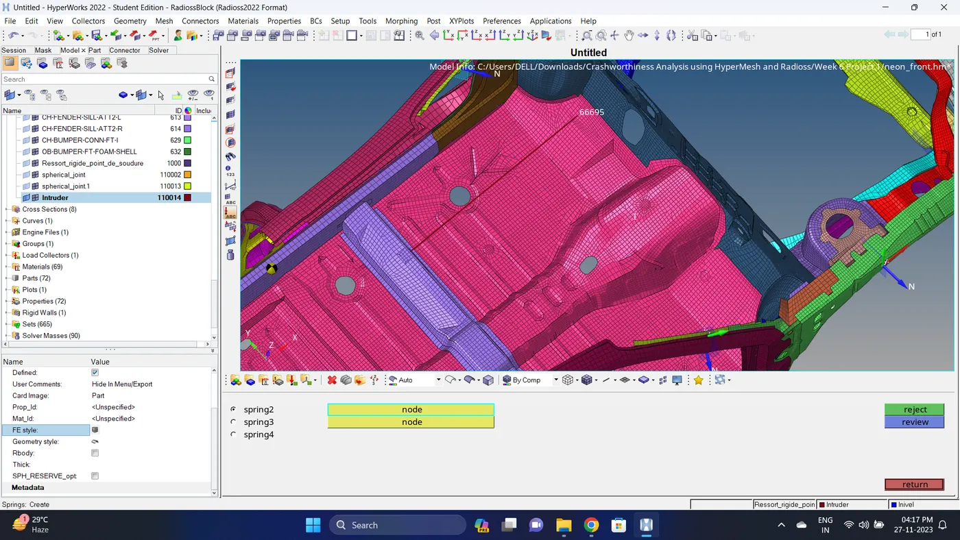
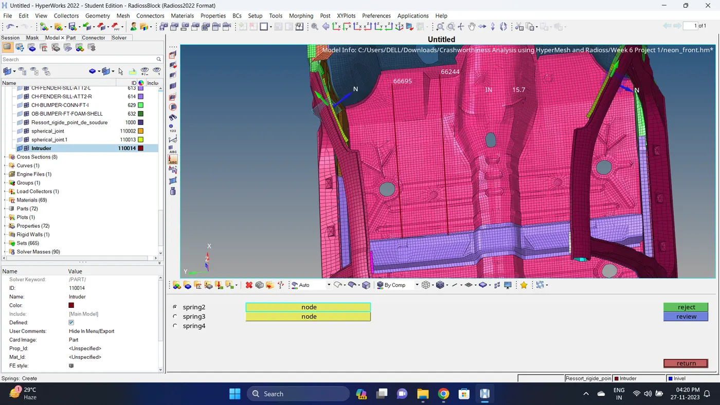
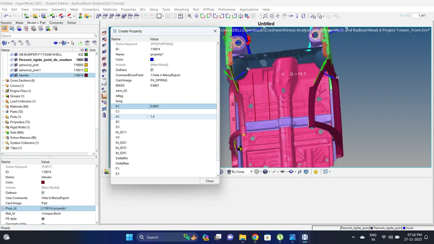
25. Create a property for spring and assign it to the component.
26. In Model deck - Cards - In ENG_DT_BRICK, ENG_DT_INTER AND ENG_DT_NODA change Tmin to 0.0005, 0.0005 and 0.0003.
Note: For checking the time step value go to Tools - Check element - time - give value and test the time step for different elements.
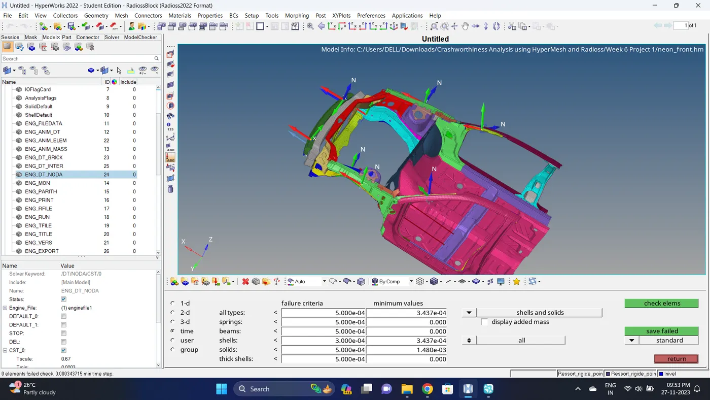
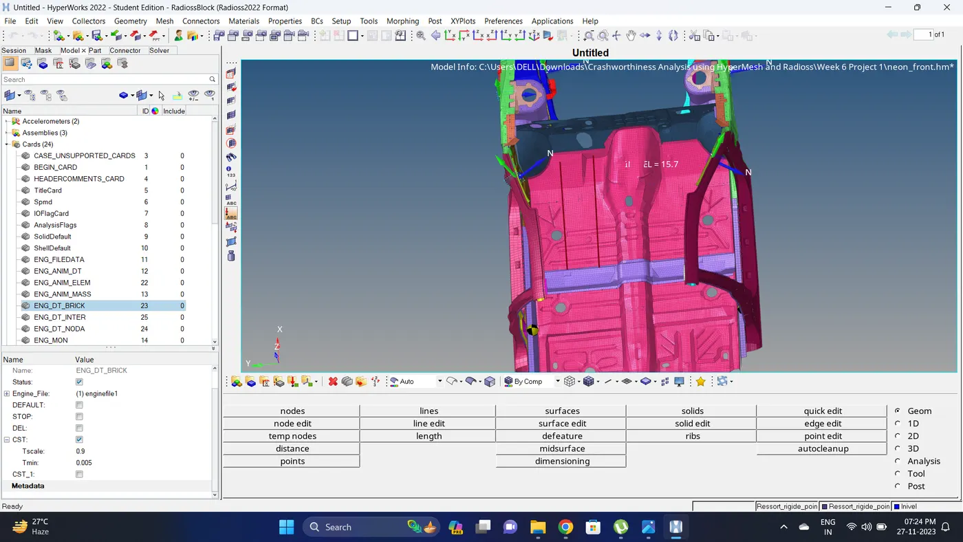
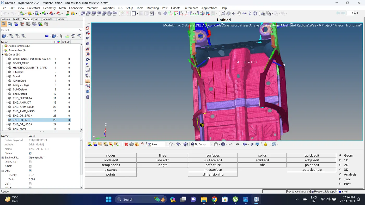
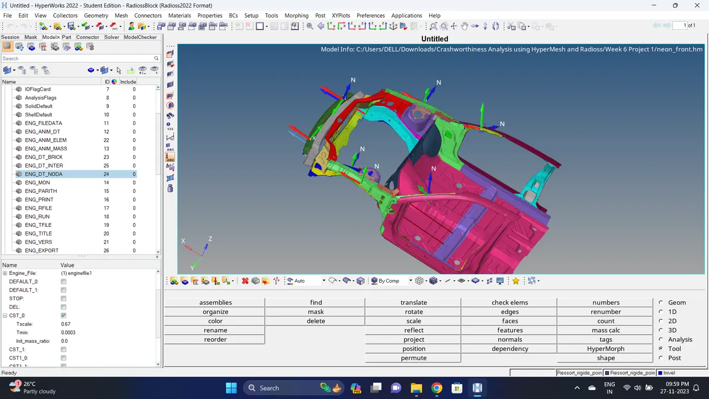
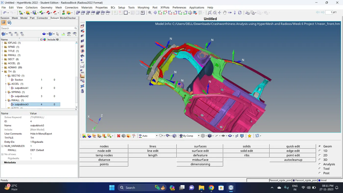
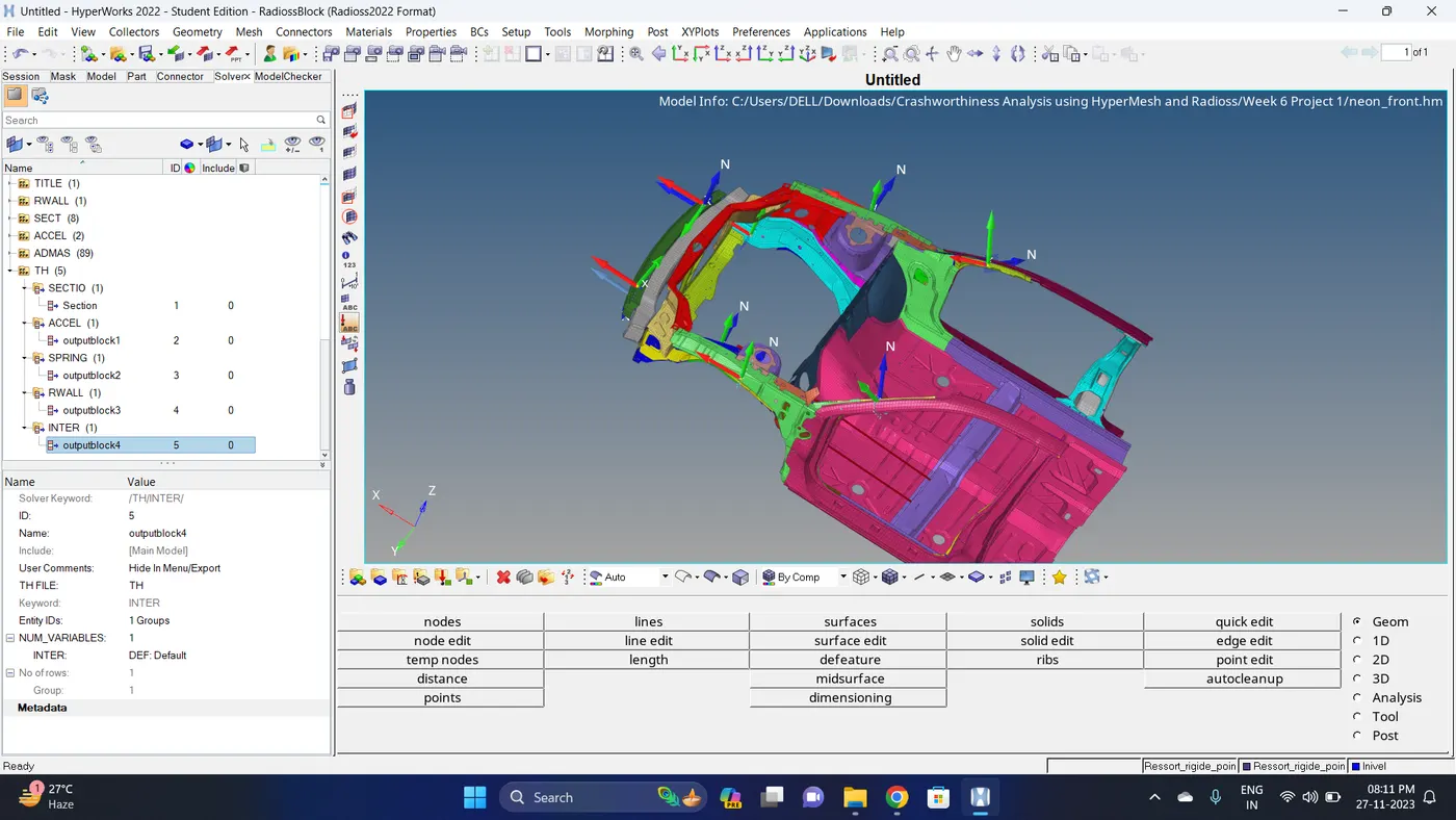
27. Create a Output request for Sectional forces, Accelerometer, Intrusion(Spring), Rigid Wall and Interface.
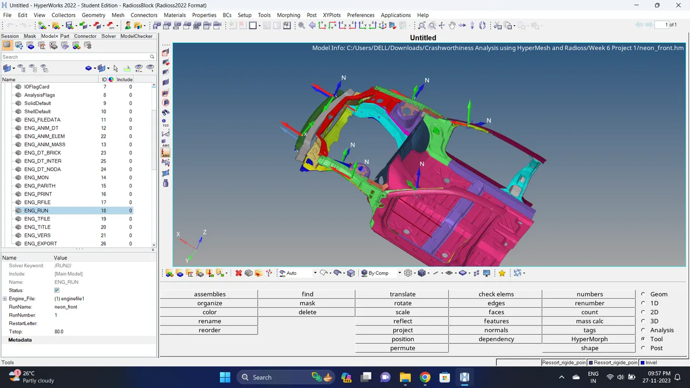
28. Check the simulation run time.
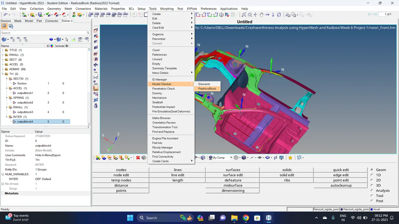
29. Go to Tools - Model Checker - RadiosBlock and Run the Model Checker.
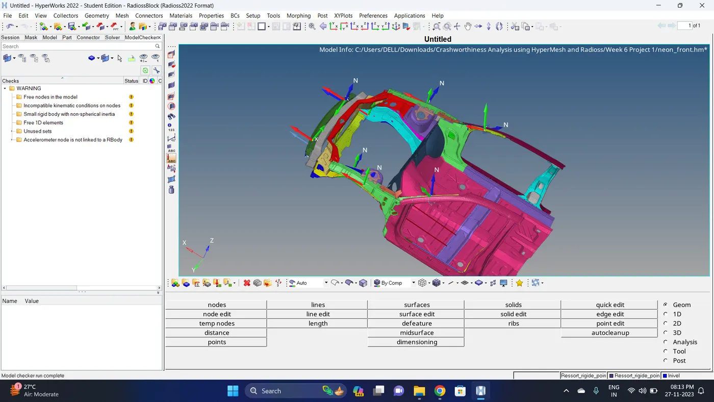
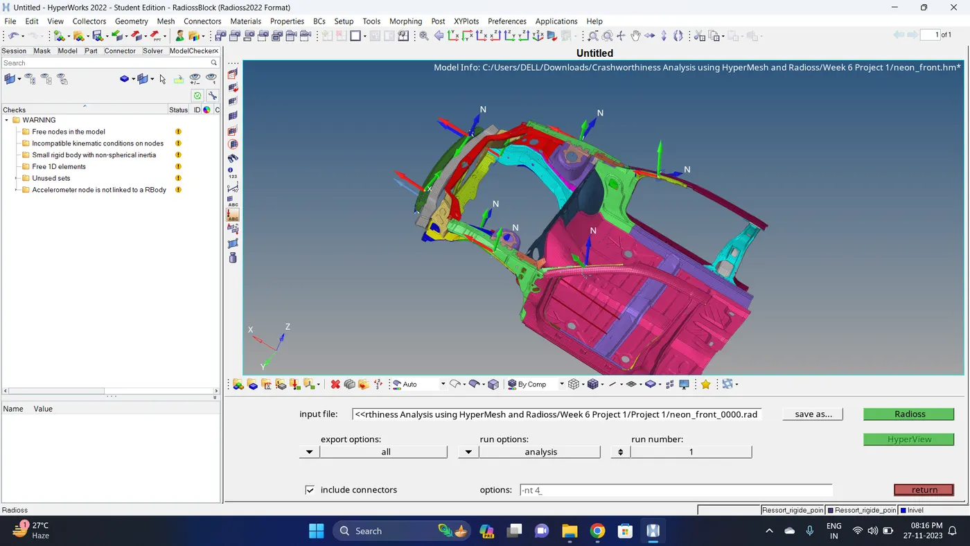
30. Run the simulation.
Go to Analysis - Radioss - Ensure that export option is set to all and Include connectors is tick - Click Radioss to run the simulation.
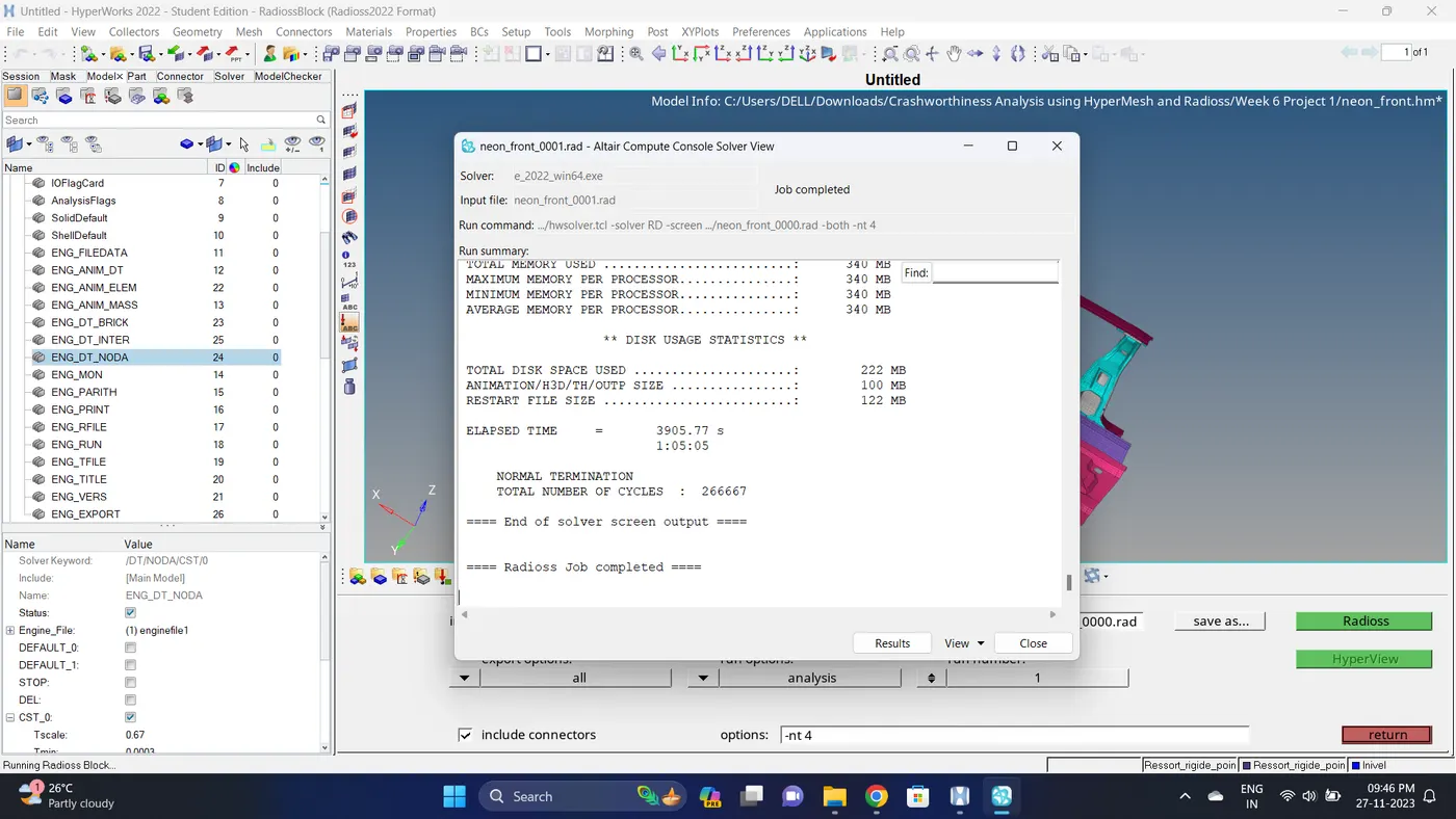
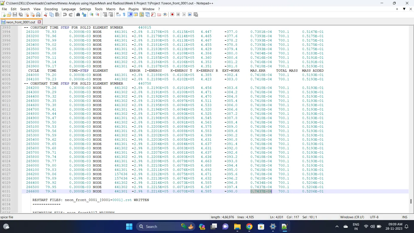
31. Open 0001.out file in notepad ++ and check the maximum total energy error and mass error.
The torelance for the energy error is -15 to +5 % and mass error is upto 2 %.
Energy error is -2.9%.
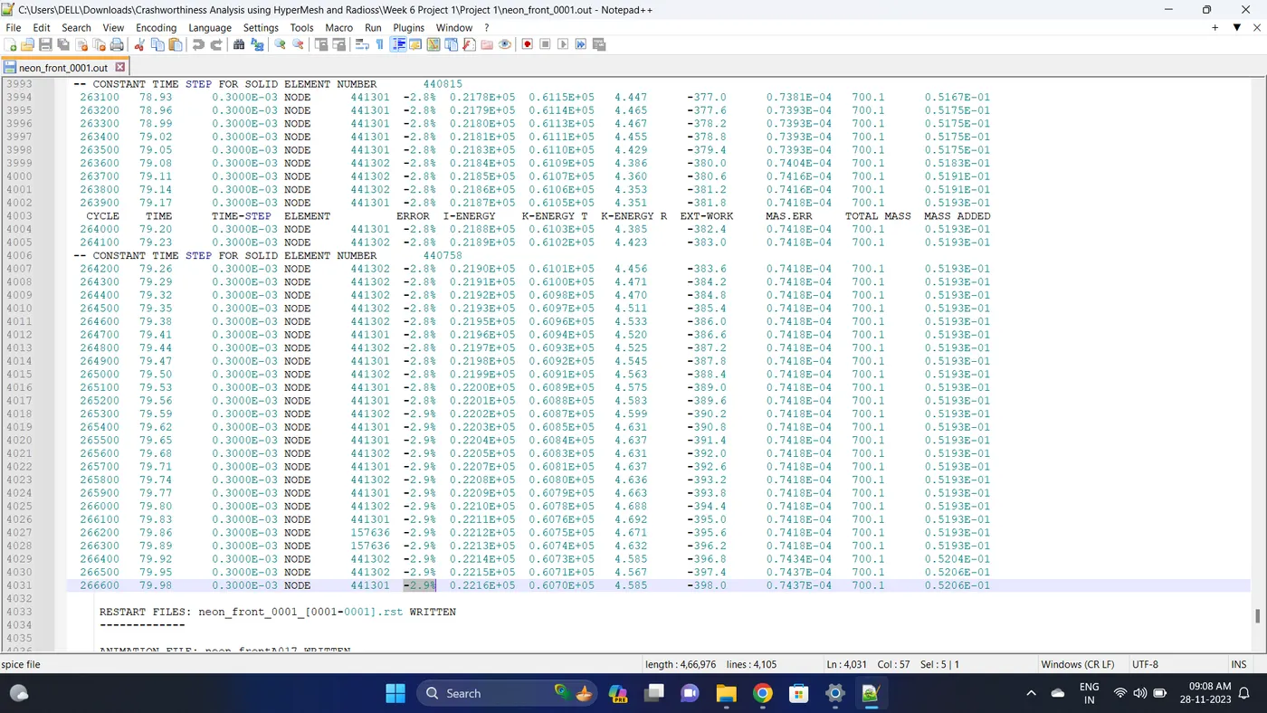
Mass error is 0.7437E-04.
32. Open the Hyperwork in Hypergraph 2D view.
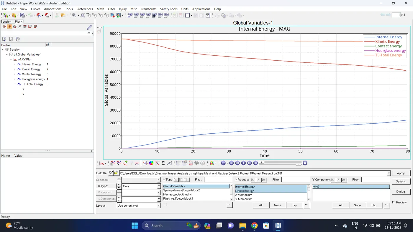
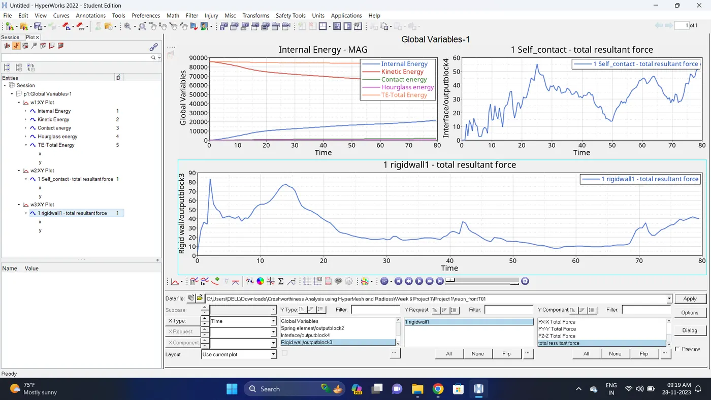
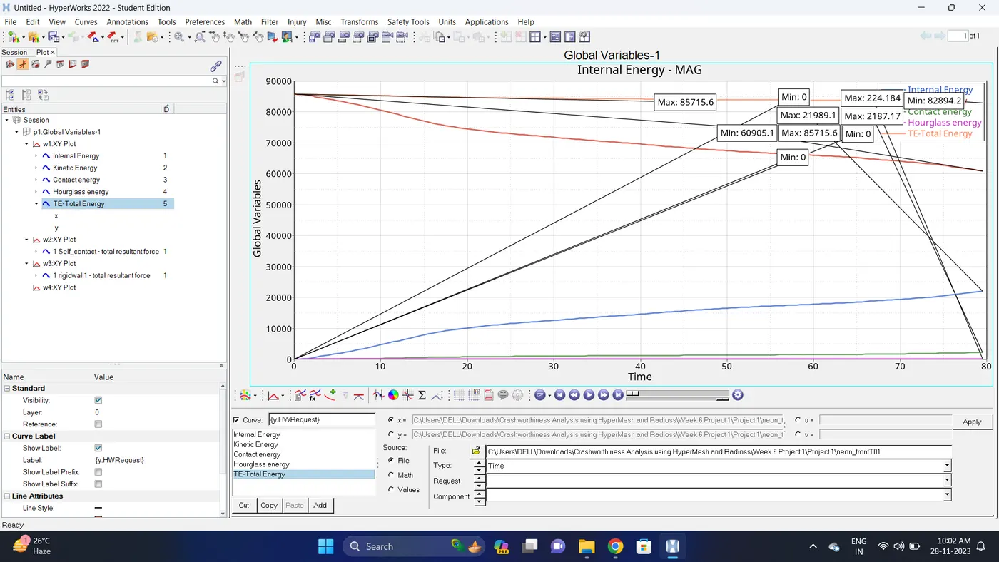
33. Open the T01 file from case_1 and select the Global Variable - Internal energy, Kinetic energy, Contact Energy, Hourglass Energy and Total Energy - Click apply to plot the graph.
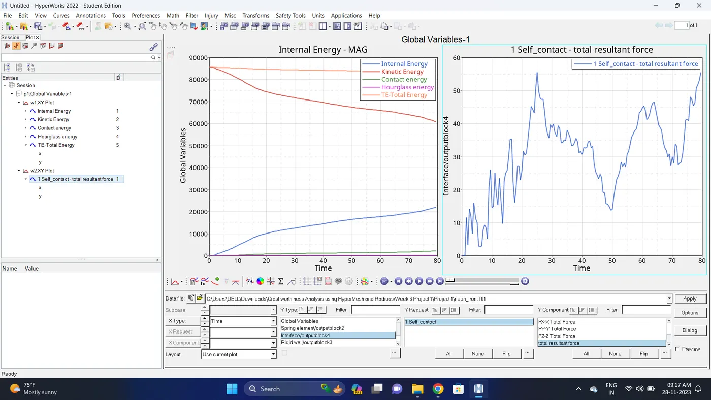
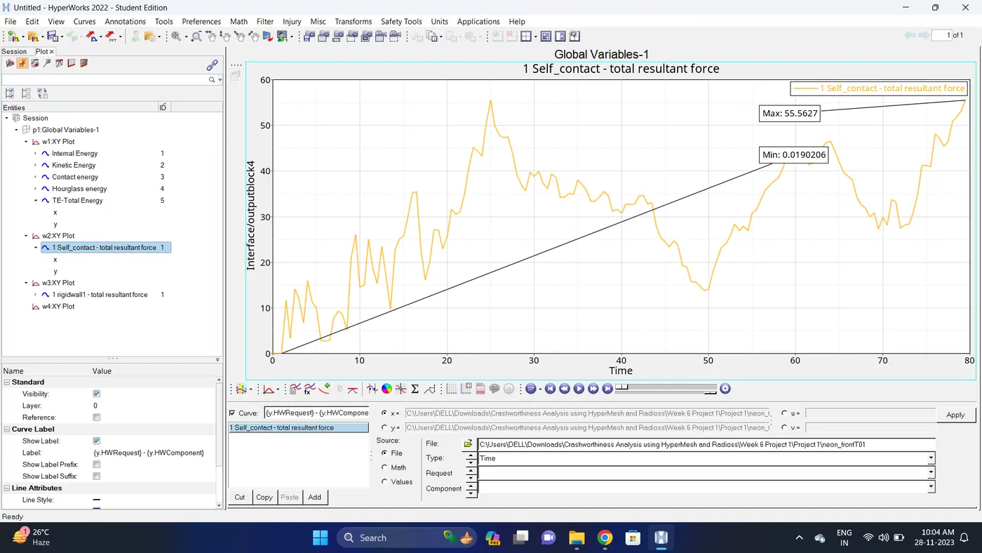
34. Change the windows page layout to 2 and in second window plot the Interface/Contact forces graph.
To plot the graph select Interface - Select self contact - total resultant force - click apply.
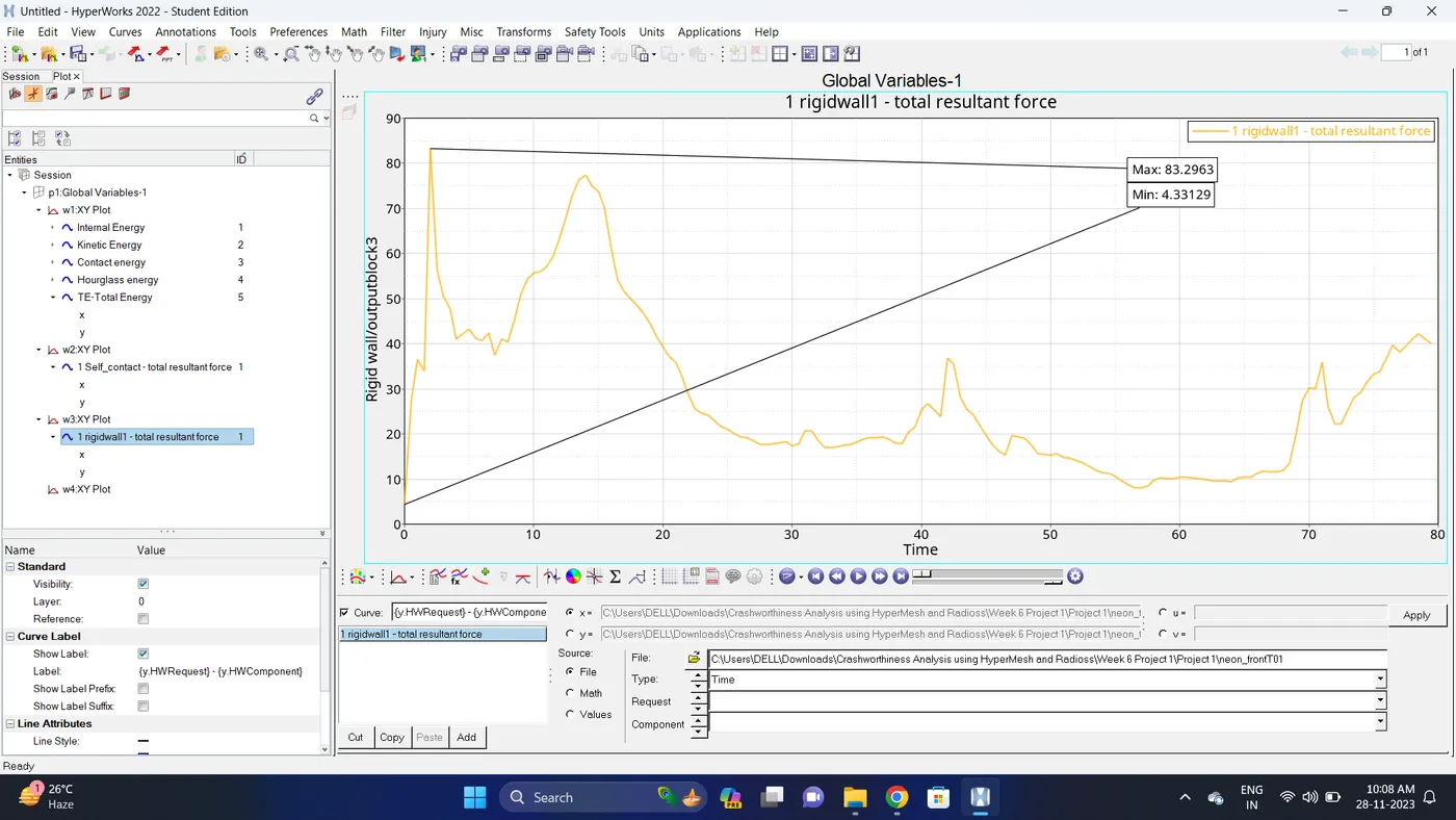
35. Change the windows page layout to 3 and in Third window plot the rigid wall forces graph.
To plot graph select Rigid wall - 1 rigidwall1 - total resultant force - click apply.
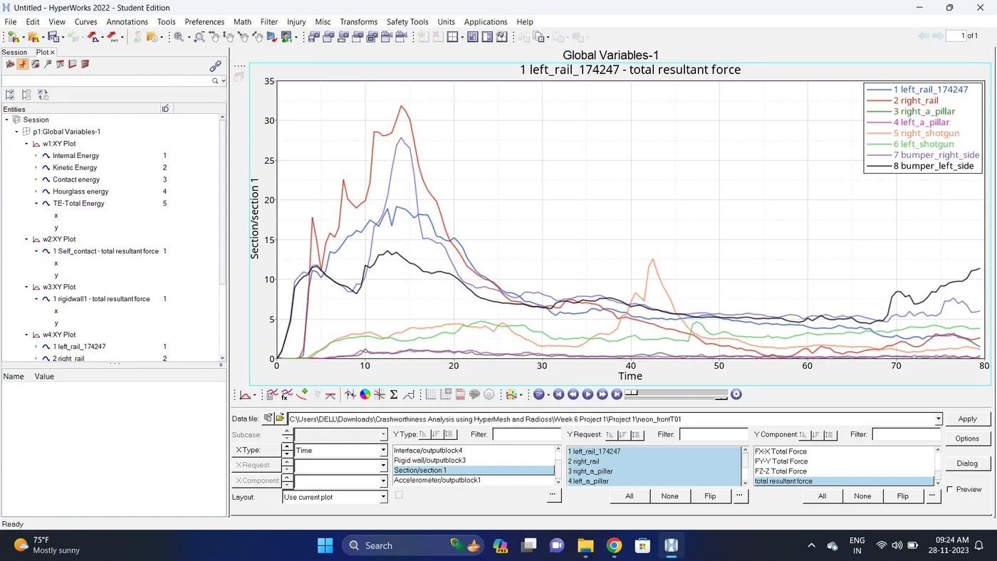
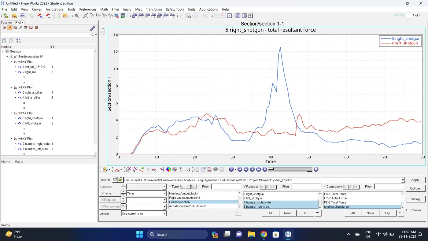
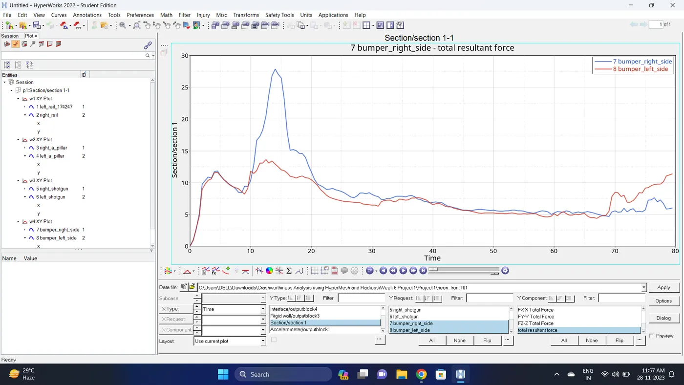
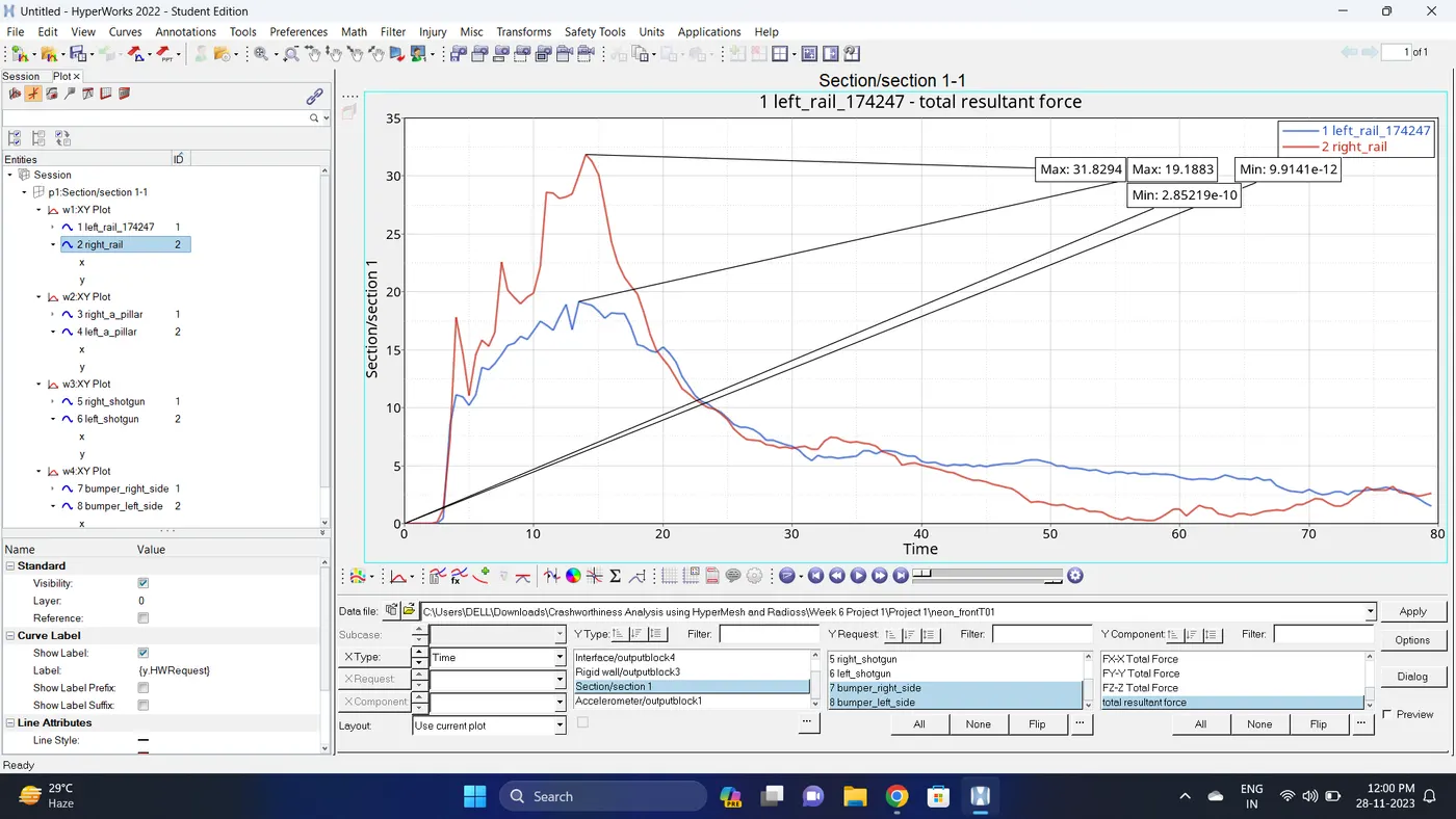
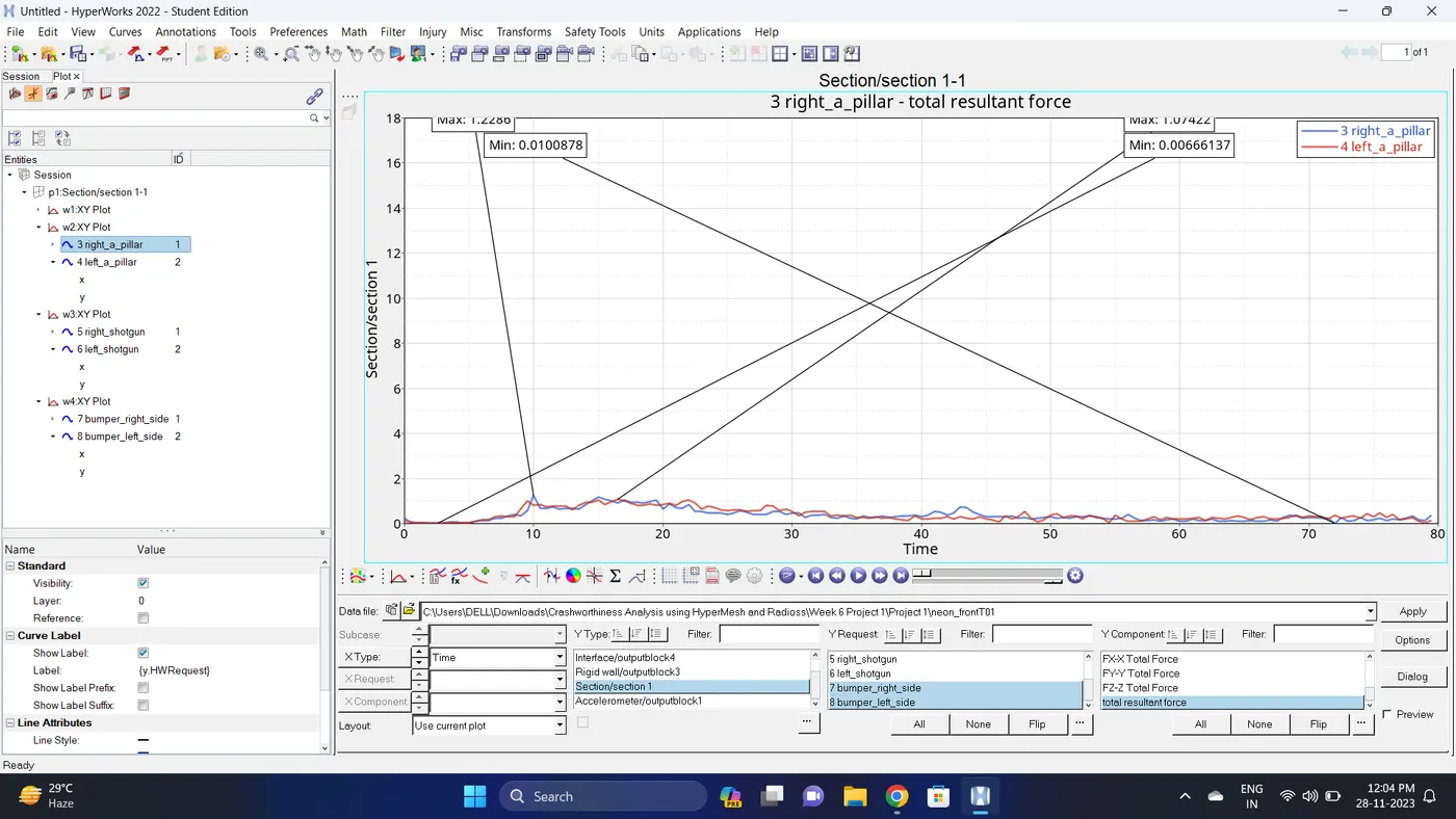
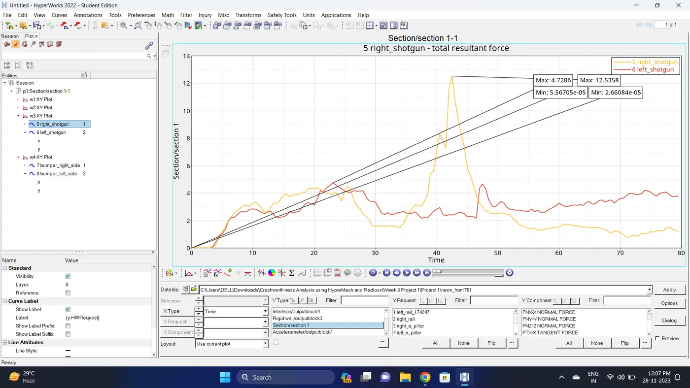
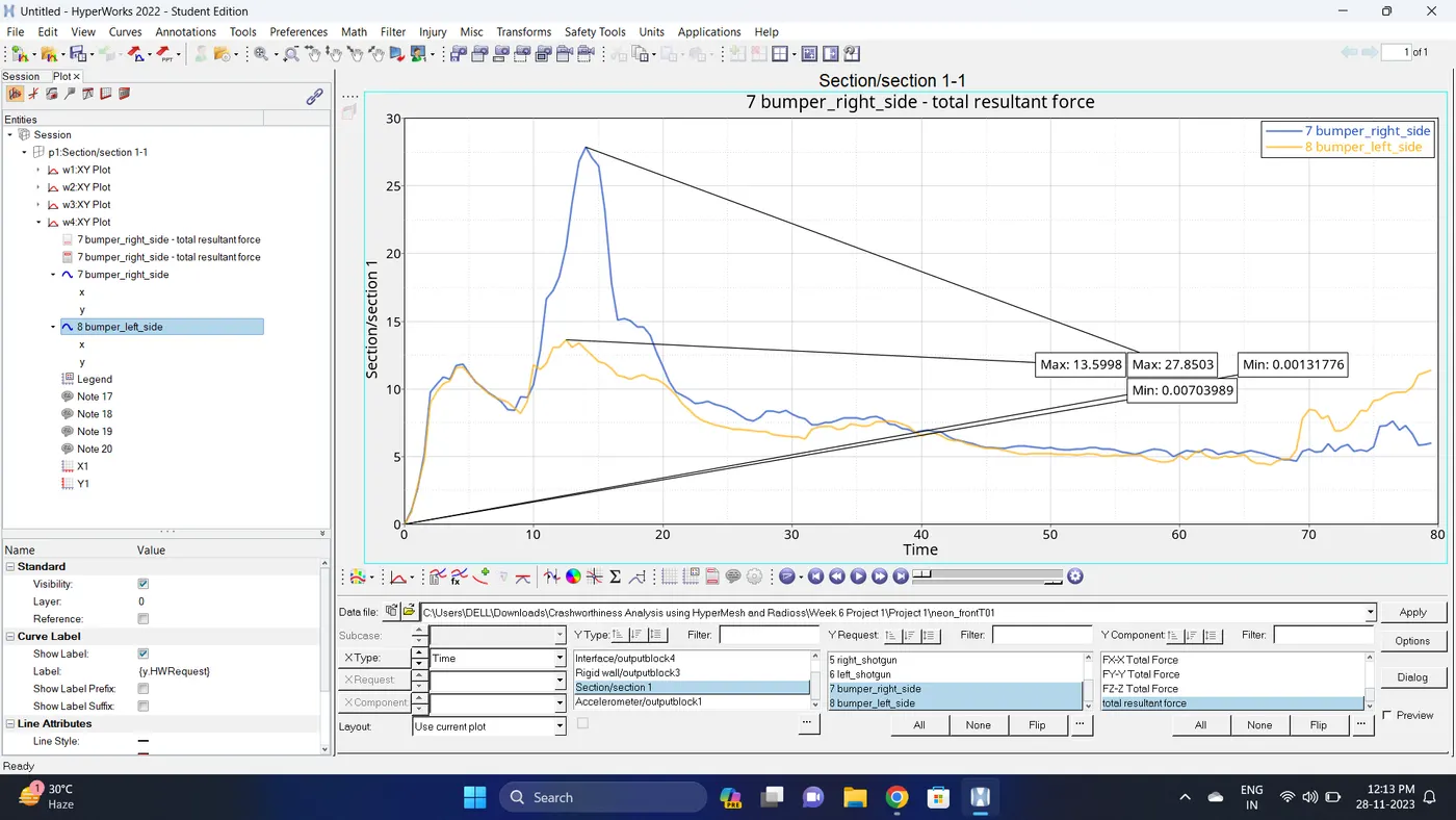
36. Open a new window page. Plot Section - Select all sections - Total resultant force - click apply.
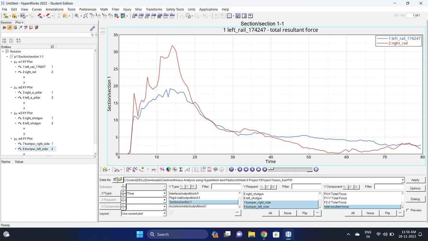
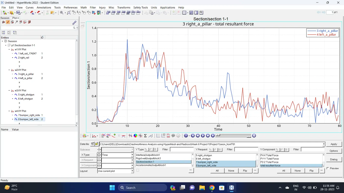
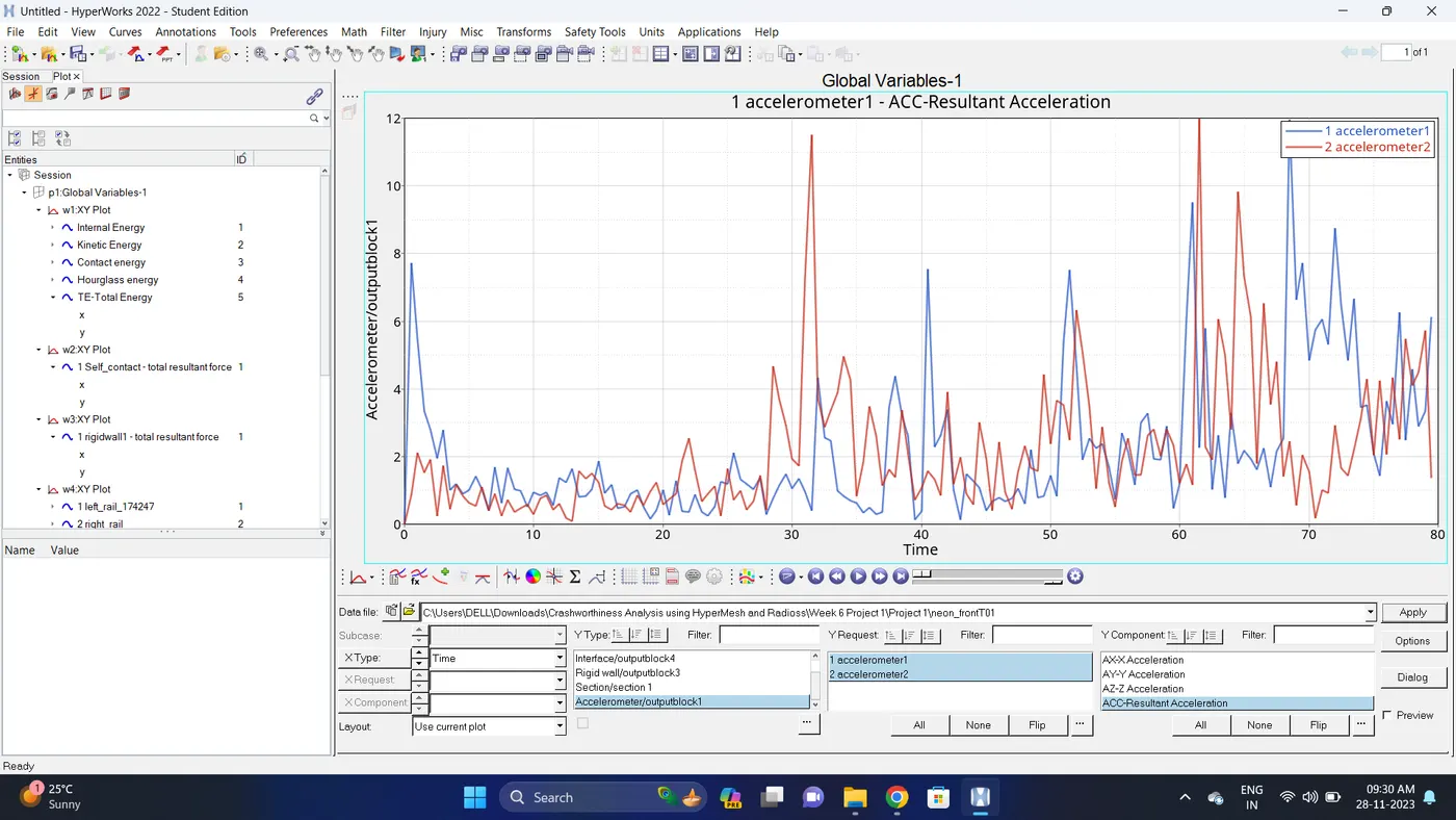
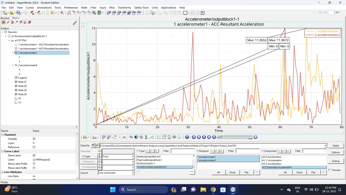
37. Open a new window page. Plot - Accelerometer - Select all the accelerometers - Resultant Acceleration.
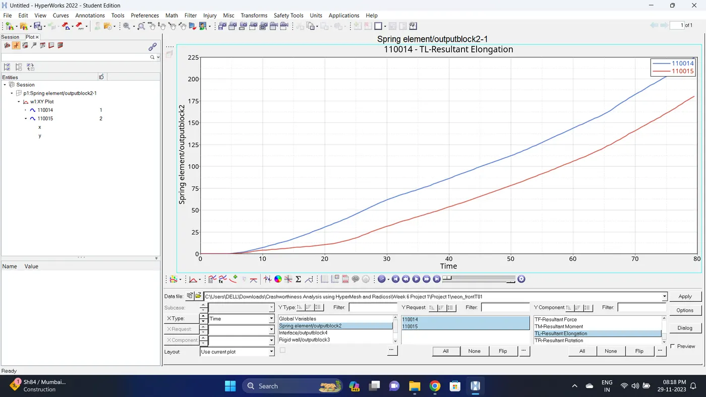
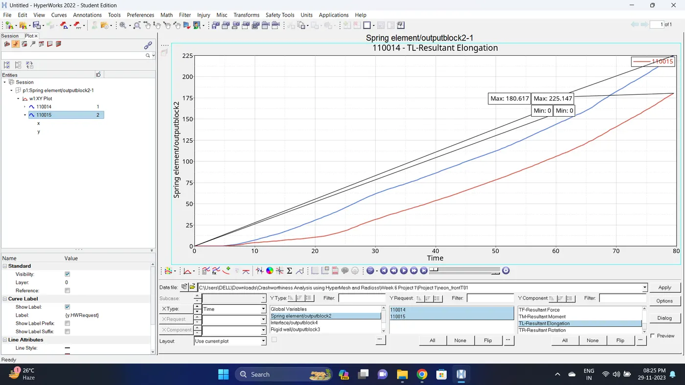
38. Open a new window page. Plot - Spring element - Select all the element - Resultant Elongation.
39. Note down the minimum and maximum value of various Energy, Rigid wall forces, Sectional forces, Interface, Acceletation and spring element by right click on any energy - Single curve math - Min Note. similarly do for maximum.
Note: after getting graph reading turn off that graph and do next reading.
| Sr. no | Name | Minimum | Maximum |
| 1 | Internal energy | 0 KN.mm | 21989.1 KN.mm |
| 2 | Kinetic energy | 60905.1 KN.mm | 85715.6 KN.mm |
| 3 | Contact Energy | 0 KN.mm | 2187.17 KN.mm |
| 4 | Hourglass Energy | 0 KN.mm | 224.184 KN.mm |
| 5 | Total Energy | 82894.2 KN.mm | 85715.6 KN.mm |
| 6 | Self Contact | 0.0190206 KN | 55.5627 KN |
| 7 | Rigid Wall forces (Total Resultant Force) | 4.33129 KN | 83.2963 KN |
| 8 | Left Rail (Total Sectional Forces) | 2.85219e-10 KN | 19.1883 KN |
| 9 | Right Rail (Total Sectional Forces) | 9.9141e-12 KN | 31.8294 KN |
| 10 | Left A Pillar (Total Sectional Forces) | 0.00666137 KN | 1.07422 KN |
| 11 | Right A Pillar (Total Sectional Forces) | 0.0100878 KN | 1.2286 KN |
| 12 | Left Shotgun (Total Sectional Forces) | 5.56705e-5 KN | 4.7286 KN |
| 13 | Right Shotgun (Total Sectional Forces) | 2.66084e-5 KN | 12.5358 KN |
| 14 | Left Bumper (Total Sectional Forces) | 0.00131776 KN | 13.5998 KN |
| 15 | Right Bumper (Total Sectional Forces) | 0.00703989 KN | 27.8503 KN |
| 16 | Left Accelerstion (accelerometer2) | 0 m/s | 11.9672 m/s |
| 17 | Right Accelerstion (accelerometer1) | 0 m/s | 11.9552 m/s |
| 18 | Intrusion 66695 | 0 mm | 180.617 mm |
| 19 | Intrusion 66244 | 0 mm | 225.147 mm |
40. Open the Hyperwork in Hyperview view and import the .h3d file.
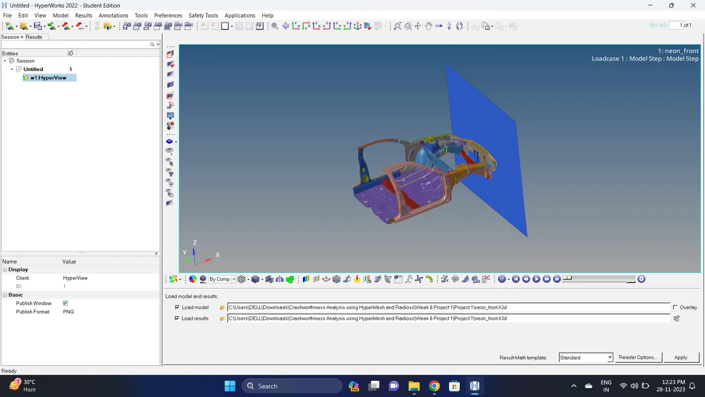
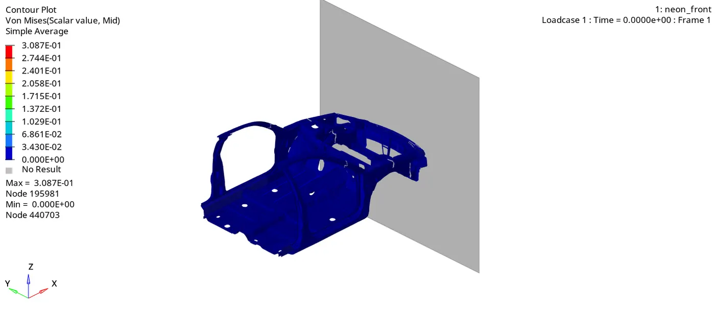
41. Go to the contour - change result type to Von mises (s), averaging method to simple, click on apply and play the animation.
Maximum stress = 0.3087 and Minimum stess is 0.
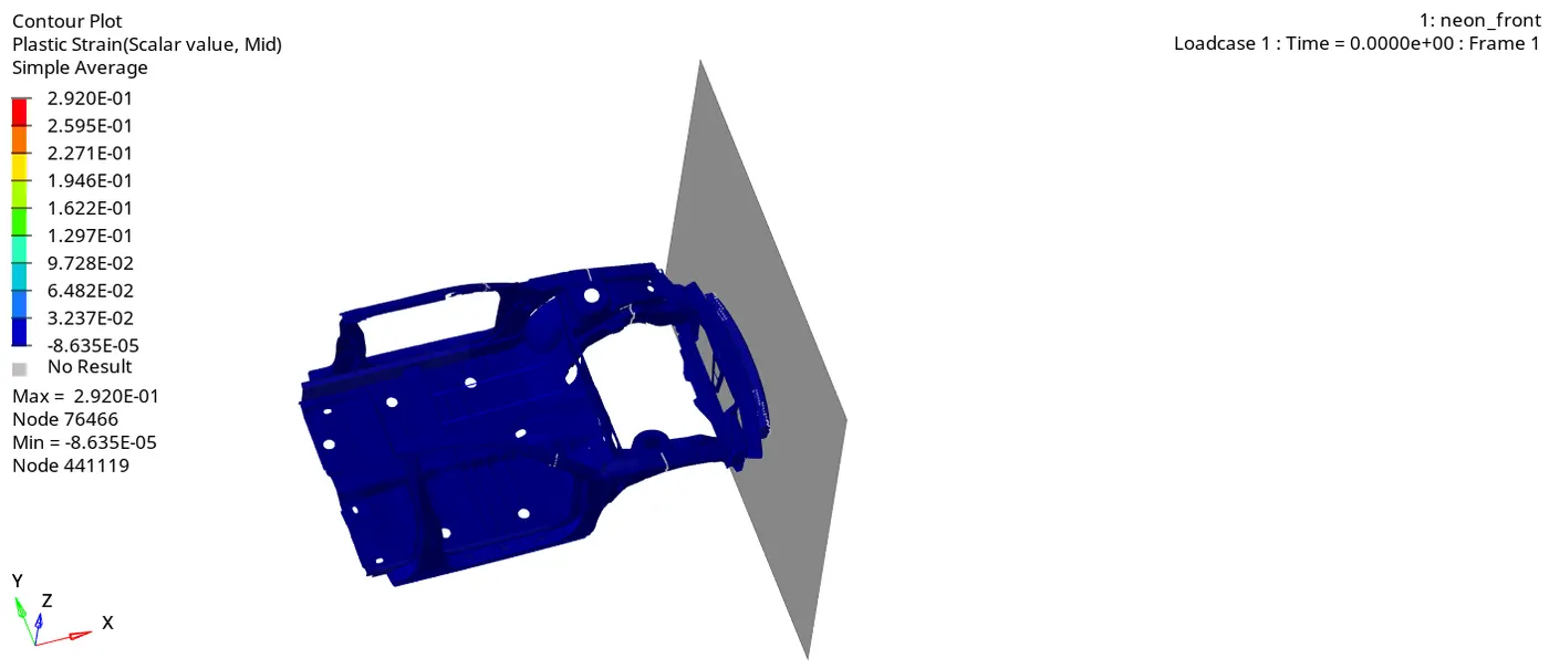
42. Go to the contour - change result type to Plastic Strain, averaging method to simple, click on apply and play the animation.
Maximum Strain is 0.292 and Minimum Strain is -8.635E-05.
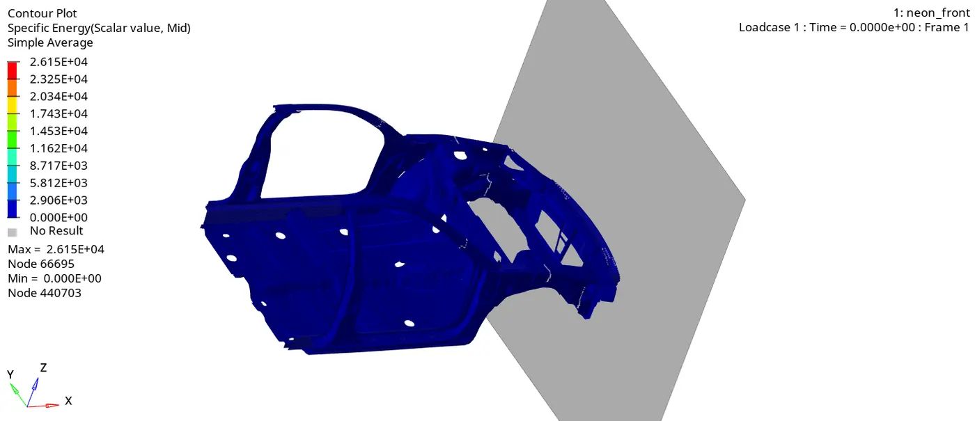
43. Go to the contour - change result type to Specific Energy, averaging method to simple, click on apply and play the animation.
Maximum Energy is 2.615E+04 and Minimum Energy is 0.
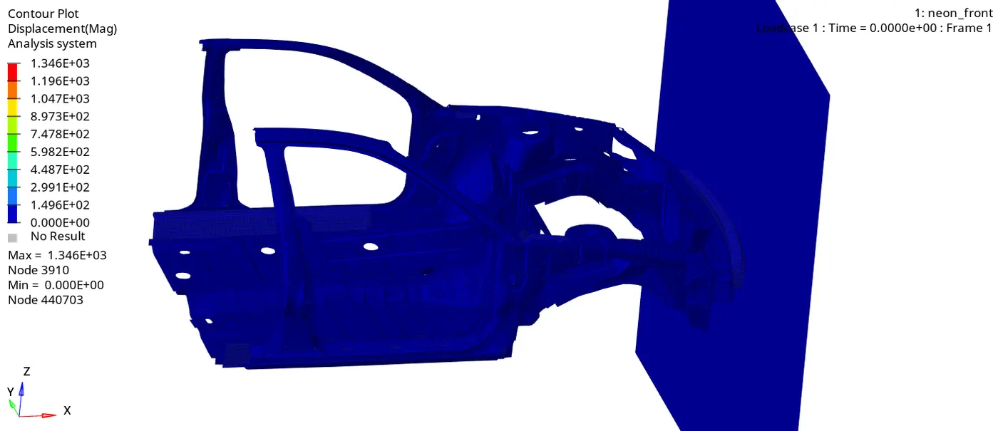
44. Go to the contour - change result type to Displacement, averaging method to simple, click on apply and play the animation.
Maximum Displacement is 1.346E+03 and Minimum Displacement is 0.
Report:
In the graph we can see that sectional forces of left side and right side are not same. This mainly happen due to the in left and right side there are uneven number of rigid body are present and Model is not complete. This may also happens due to material properties also.
We saw in the animation that the most deformation took place in the frontal area and the stress is then passed to the rest of the components of the car. We observed that the impact of the crash is taking mostly at the frontal region of the car and by looking at this we can say that the seating area of the driver and passenger will be also impacted which can cause injury to them.
In accelerometer 1 and accelerometer 2, the curve fluctuates drastically during the crash.
In Intrusion 1 and Intrusion 2 graph, the displacement curve linearly increases with respect to time.
Result:
Frontal crash simulation is done successfully.
Conclusion:
Thus, the model was simulated for a frontal crash test and the results were discussed. From the output file, the energy error and mass error are in the acceptable range so it concludes that the simulation is pretty stable. Results are not the most accurate even though the mass is balanced & COG is located at its exact position for more accurate results, it is advised to use a full-scale neon model for the simulation.
Note: The Simulation files are attached to the Google Drive the link is povided in the notepad file.