Assignment 6-Frontal Crash Simulation Challenge
FRONTAL CRASH SIMULATION
OBJECTIVE
The main objective of frontal crash analysis of neon BIW is to know how much force is recieved at different components at neon BIW like cross rail shot gun .And to know about intrusions of a model as well as acceleration .The other objective of frontal crash analysis of neon BIW is to create a global contact interface ,rigid wall , add the masses to reach a target weight 700 kg while getting COG about the required range , intial velocity of 35 mph .Finally creating cross section as well as instruction
CASE STEP AND EXECUTION
- Check unit system and either follow [Mg mm s] or [Kg mm ms].
- And we followed Kgg mm ms throught process
IMPORTING MODEL
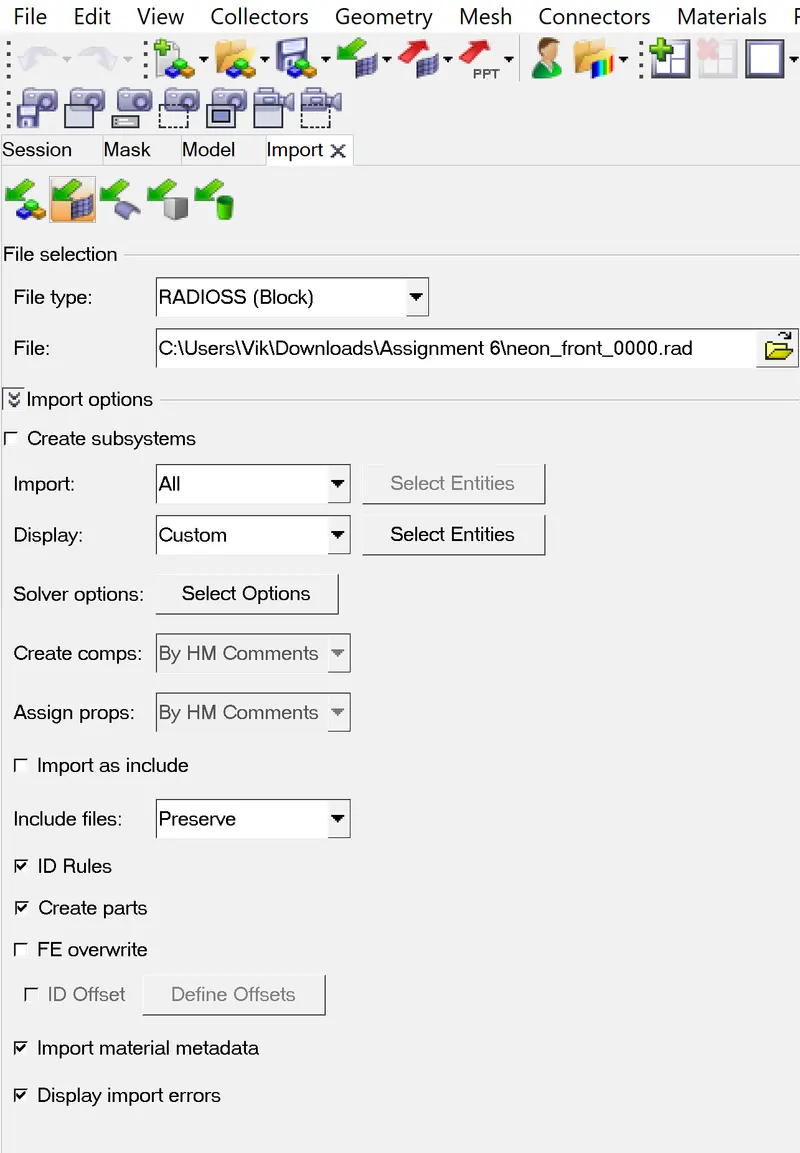
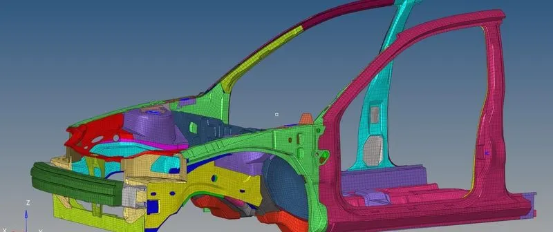
- The model is imported into hypermesh by click on import solver deck -Search the neon_front_0000.rad file and click import
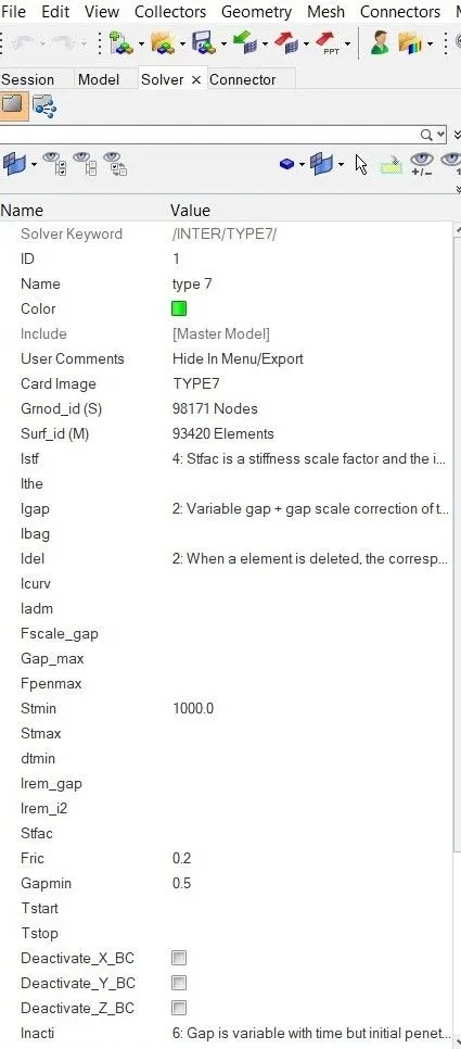
Create an appropriate interface, friction 0.2, and recommended parameters.
- Already a contact is defined in the model we have to delete that interface and to create a new interface TYPE 7 with recommended parameters
Importance Interface Parameters
Igap = Determine how the size of the gap is calculated
Gapmin = Minimum gap for activation of interface
Inacti = Action how the stiffness of the interface is calculated
Iform = Friction formulation
Stim = Minimum stiffness to use in the interface
Idel = Update for deleted elements Due to failure
Recommended contact parameters for interface type 7
Istf = 4
Igap = 2
Fscale_Gap = 0.8
INACTI = 6
Gap_min = 0.5
Fric = 0.2
Iform = 2
- Now run the model analysis to check for error and warnings
- Make sure of no penentrations and intersection .If there is any penentration correct it or simply use the gapmin value to reduce the penentation correct it or simply use the gapmin value to reduce the penentrations
- Rigid body issues if any corrected by using hypercrash
RIGID WALL CREATION
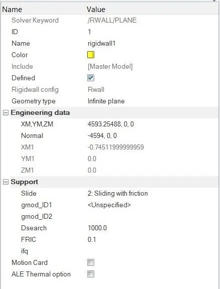
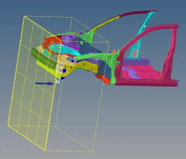
- An obstacle like infinite rigid wall is created infront of the bumper with some parameters like friction = 0.1 and Dsearch as 1000
- A rigid wall is created by Solver-Create - Rigid wall - plane - then a dialgoue box will open and assign the required values
ADDED MASS
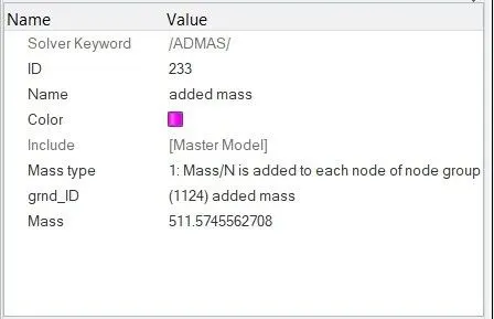
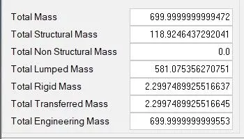
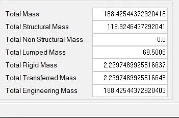
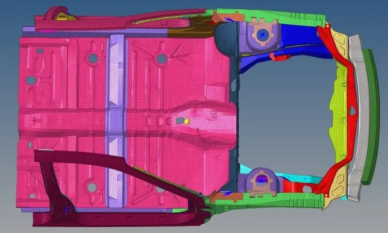
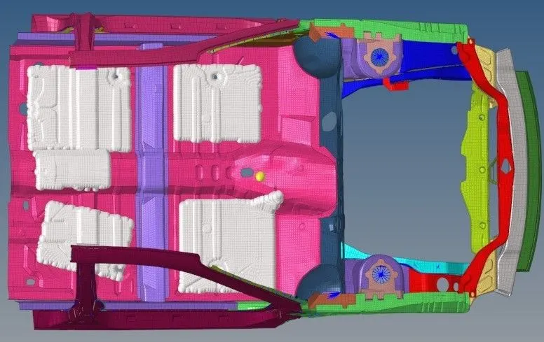
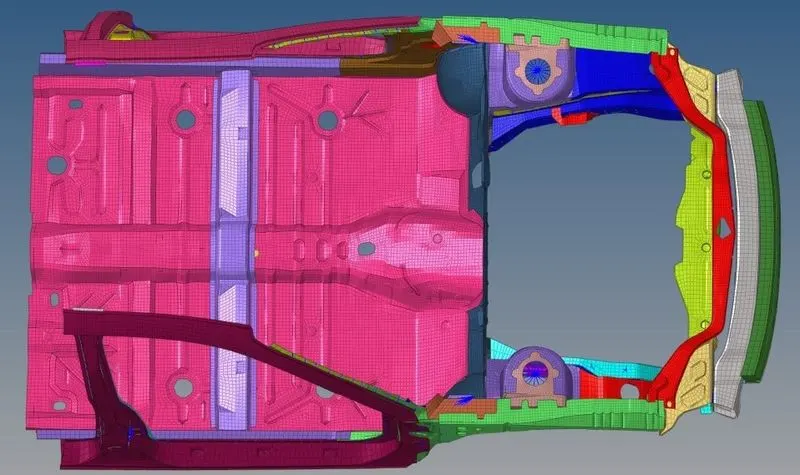
- Initially the model has a weight of 188.42 kg we have to add the mass to reach a target weight of 700 kg to get COG about the required range . We have to add the mass at the floor of the BIW in order to get the COG at required range
- A wide variety of mass type option are available to add the mass we have to choose the option 1 for better results
INITIAL VELOCITY
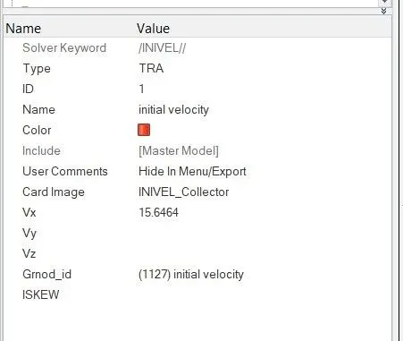
We have to create a initial velocity in order to perform the crash .Generally we have to give intial velocity of 35 mph which is a standard value according to the crash standards .As we have following the Kg mm ms units we have to change the 35 mph to required value
1 Mile = 1.609344km
1Km = 1000m
1m = 1000mm
1 sec = 1000ms
Based on this value we changed the value from 35mph to 15.6464mm/ms
TIME STEP 0.5 TO 0.1 MICRO SECONDS
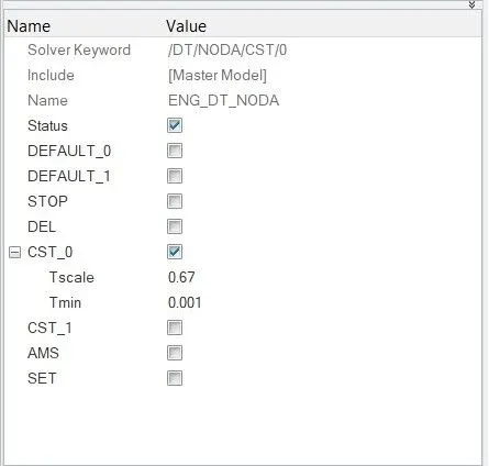
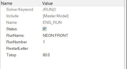
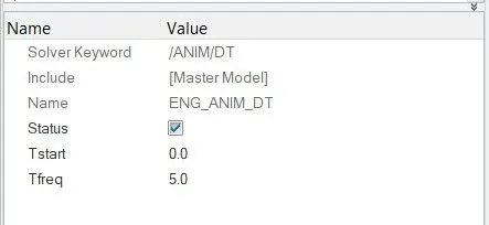
We have to create a time step in between 0.5 ms to 0.1 ms .And we have created the respected values as shown . Run the time as 80 ms and Tfreq as 5ms.Use the model checker to ensure good quality
OUTPUT REQUEST
We have to create cross section at different components of BIW in order to get cross sectional forces acceleration to get acceleration curve intrusion to know the displacement
- Sectional force in the rails at location of indicated node 174247
- Axial force recieved on the rails from bumper
- A pillar cross section
- Acceleration curve recieved on the accelerometer at base B pillar
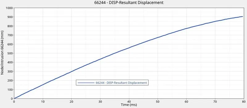
- Intrusion on the dash wall 6669566244
CROSS SECTION CREATION
We have to create the cross section to know the forces acting on that particular section . We have to create section on the following components with right hand side as well as left hand side
Cross section at
Rails both LH and RH
Shot gun LH and RH
A pillar LH and RH
Go to solver - Create - Sec - ok . Then a dialgoue box will be open
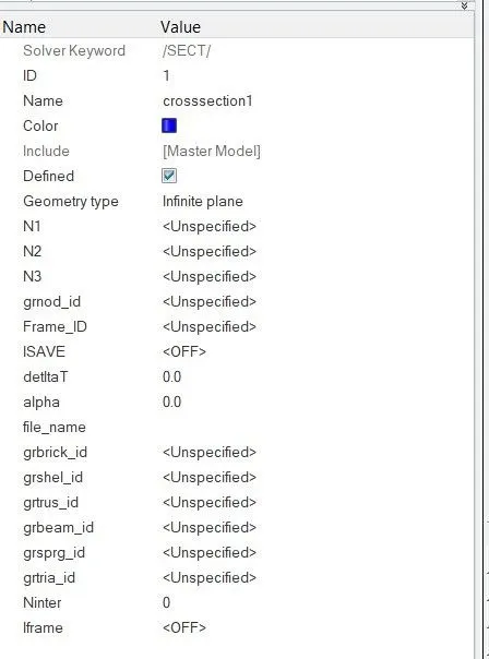
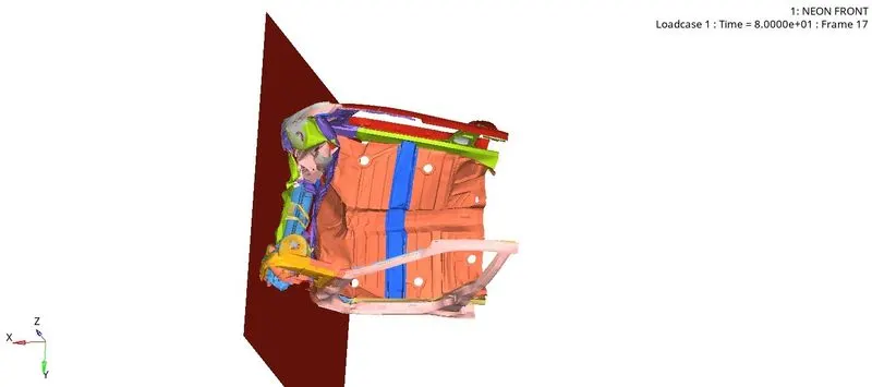
Before creating the cross section we have to create a movable skew at the respected location and add the skew in this dialgoue box .Then select the elements around that skew in at least two columns of elements through out all sides as shown.Select geshel_id if we got the quad element at respected skew and select the grtria_id we got the tria element at respected skew .Assign some values to that card such as ISAVE as 0 delta as 0.1 alpha as 0.65 and Iframe as 12 .Perform the same method for the other components and create the required cross section
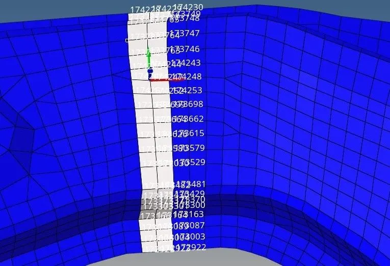
- After creating all cross section we have to create the accelerometers
CREATING ACCELEROMETERS
To get an acceleration curve recieve on the accelerometer at base 8 pillar we are creating the accelerometers.We have to create the accelometers on the both sides .Select the node at respected place where we have to create the accelerometers .
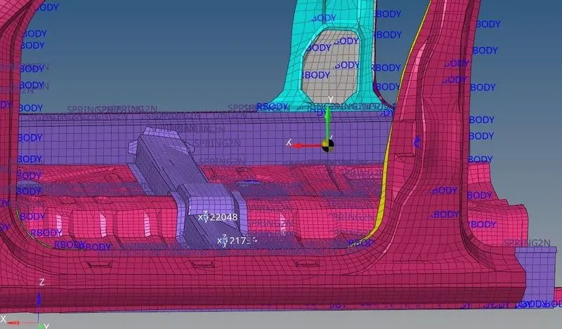
CREATING INTRUSION
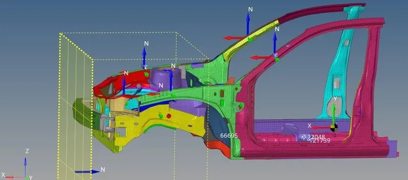
We have to create an intrusion on the dash wall at a location 666566244 to know the displacement of the particular wall into the occupant area .For this we have to create a fixed skew and make the respected node in one position .
CREATING OUTPUTBLOCK
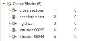
Finally we have to delete the already requested output block and create a new out put blocks for cross section accelerometers intrusion at 66695 and intrusion at 66244
RUN THE SIMULATION
After creating all required output as in hypemesh we have to run the simulation by using radioos .
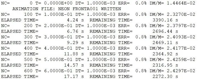
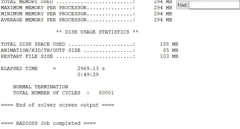
- Remaining time simulation time = 3360.16s
- Elapsed time = 2969.13s
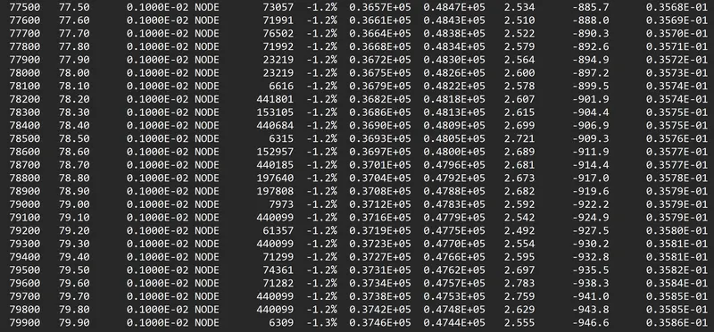
- Energy error = -1.3%
- Mass error = 0.3586E -01
- Total number of cycles = 80001
ENERGY ERROR
Bascially energy error must be negative and decreasing .The error must be less than 15% at the end of computation as per the condition .If the error is below 15% than the results could be acceptable
So from the above at the end of computation the energy error is -1.3 % and mass error is 0.3586E -01 As per the condition the energy error is -1.3% which is below 15% and results could be acceptable for further simulation and plot graphs
PLOTTING GRAPHS
SECTION FORCE IN THE RAIL COMPONENTS
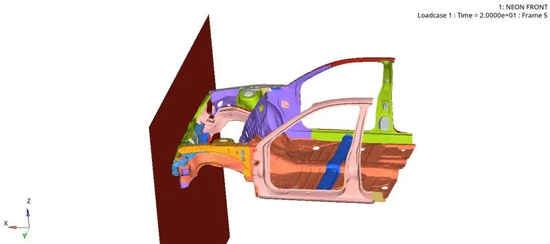
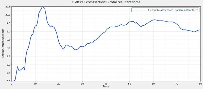
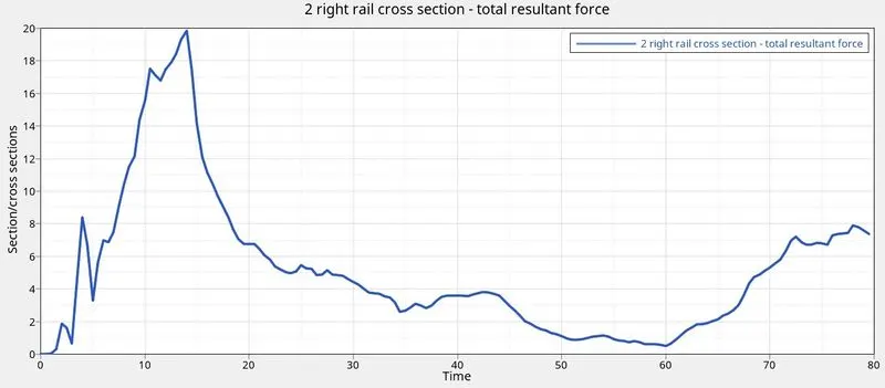
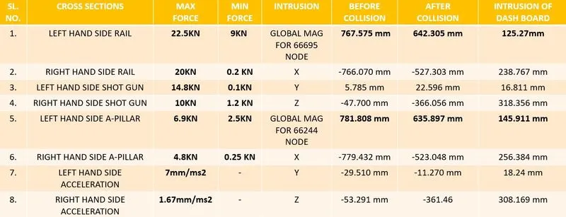
From above plot we can see that the maximum foce in left handside of a rail is 22.5KN which is around the 13ms via right hand side of a rail is 20KN at around 14ms and minimum force in the left hand side of a rail is 9KN which is around 22ms via in right handside of a rail is 0.2KN at around 60ms
SECTIONAL FORCE IN THE SHOT GUN COMPONENETS
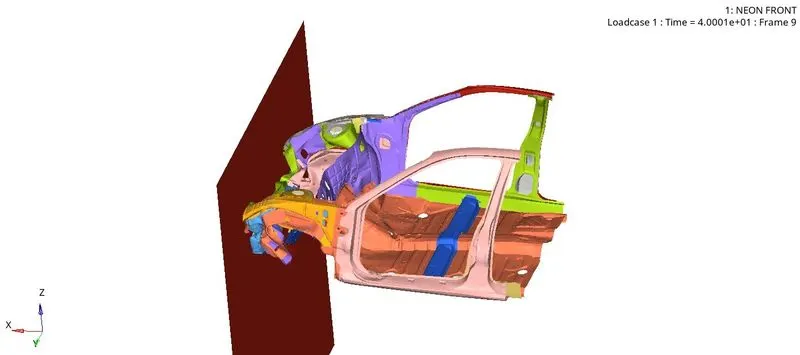
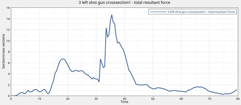
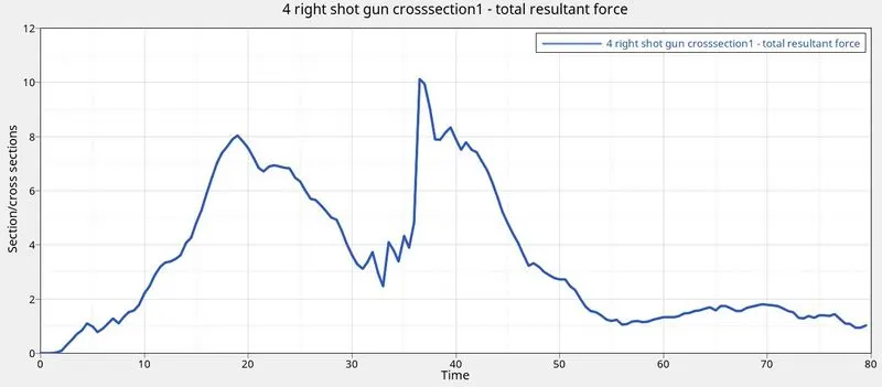
From above plot we can see that the maximum foce in left handside of a shot gun is 14.8KN which is around the 36ms via right hand side of a shot gun is 10KN at around 37ms and minimum force in the left hand side of a shot gun is 0.1KN which is around 74ms via in right handside of a shot gun is 1.2KN at around 78ms
SECTIONAL FORCE IN THE A PILLAR COMPONENTS
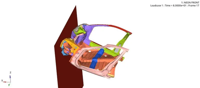
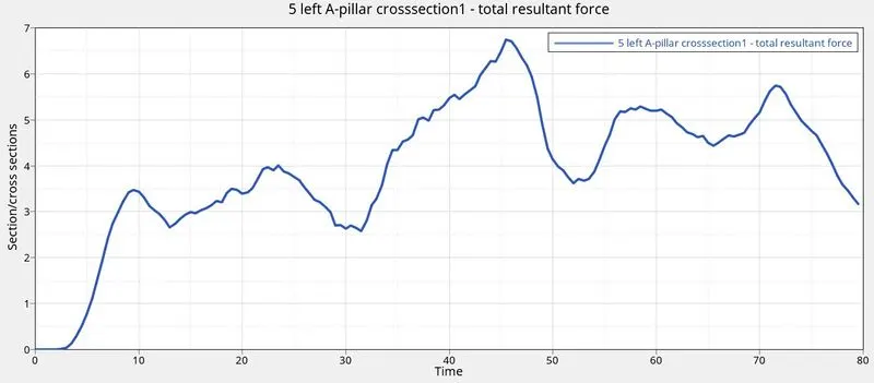
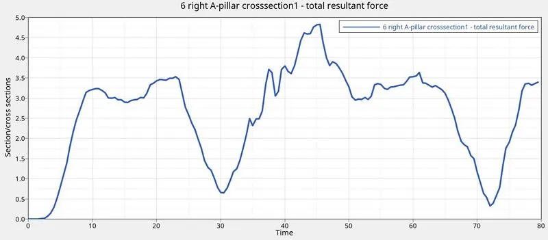
From above plot we can see that the maximum foce in left handside of a pillar is 6.9KN which is around the 46ms via right hand side of a pillar is 4.8 KN at around 47ms and minimum force in the left hand side of a pillar is 2.5 KN which is around 32ms via in right handside of a pillar is 0.25KN at around 72ms
Acceleration curve recieved on the accelerometer at base of B pillar
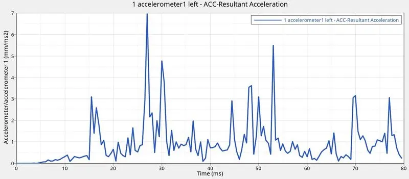
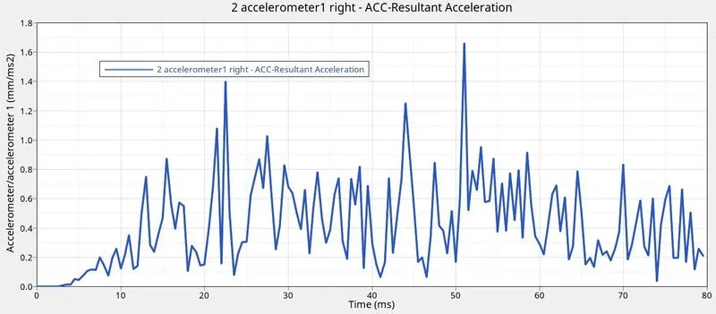
From the above plot the maximum acceleration on the left hand side is 7mm/ms2 where as in right hand side the maximum acceleration is 1.67mm/ms2
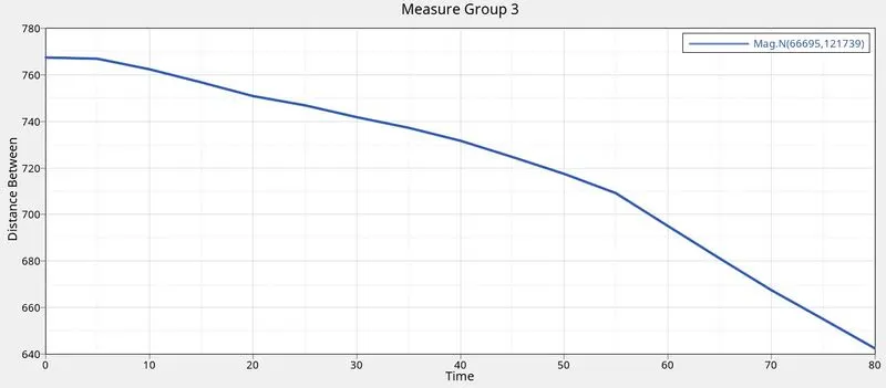
INTRUSION ON THE DASH WALL 6669566244
The purpose of intrusion to know the displacement of the particular wall into the occupant area
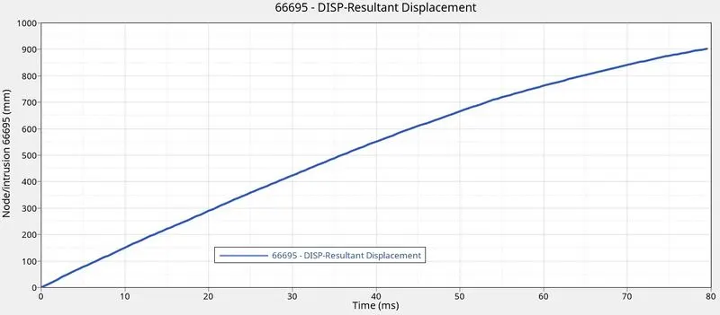
INTRUSION ON DASH WALL AT NODE 66695
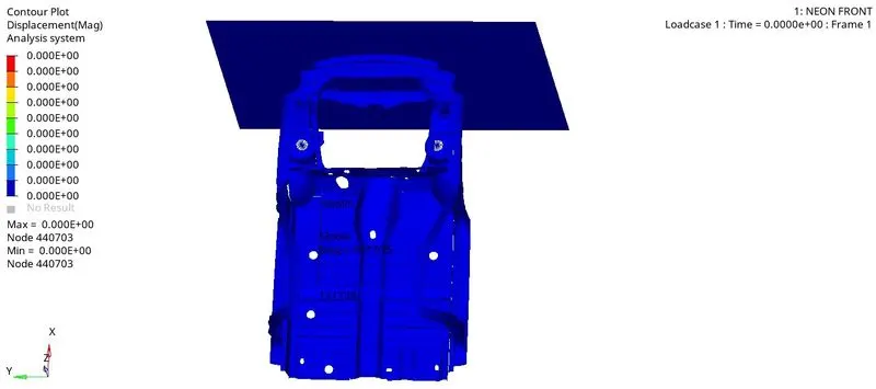
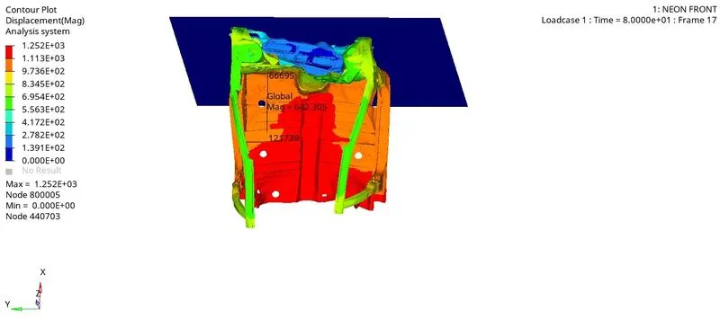
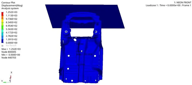
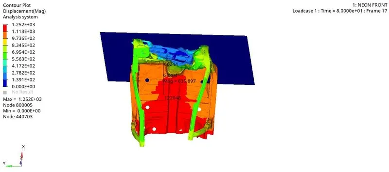
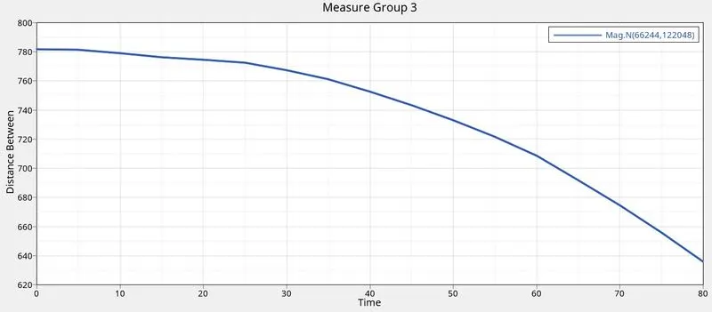
INTRUSION ON DASH WALL AT NODE 66244
The intrusion is measured with respect to node 122048
Before the collision the distance between two point is 781.808mm
RESULT
CONCLUSION
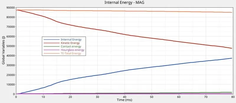
When a collision is take place a reaction force will generate from the wall which is generally called as kinetic energy .This energy has huge amount of impact .If it is taken by the passenger there is chance of injury .In order to over come this the energy should be absorbed by the car component itself from the plot we can see that there is a increase in internal energy and decrease in kinetic energy .By this we can say that the energy is absorbed by the components .The total energy remains constant .So the kinetic energy is converted into internal energy
- The contact energy remains constant due to implementation of recommended parameters
- The hour glass energy is also remain constant due to use of recommended parameters
- Finally conclude is the the energy is absorbed by the components with a decreasing manner
LINK : https://drive.google.com/file/d/1DNbWKzxhBn4zDANn8Osy1ixgsFYkf1kY/view?usp=sharing