Assignment 6-Frontal Crash Simulation Challenge
OBJECTIVE :
- Analysis Of the Frontal Crash of the Neon car Model .
- Making the Model Run properly using the Various Kinematic and Loading Conditions.
- Checking for the Error and debuging them for proper runing of the Model .
- Simulating the full model in Hyperview .
- Analysing the various Energy Graphs For Better study of the Crash Simulation .
Theory :
Body in white (BIW) is the stage in Automobile Manufacturing in which a car body's frame has been joined together, that is before painting and before the motor, chassis sub-assemblies, or trim (glass, door locks/handles, seats, upholstery, electronics, etc.) have been integrated into the structure. Assembly involves different techniques such asWelding (spot, MIG/MAG),Rivating , Clinching , Bonding and laser Brazing .
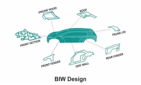
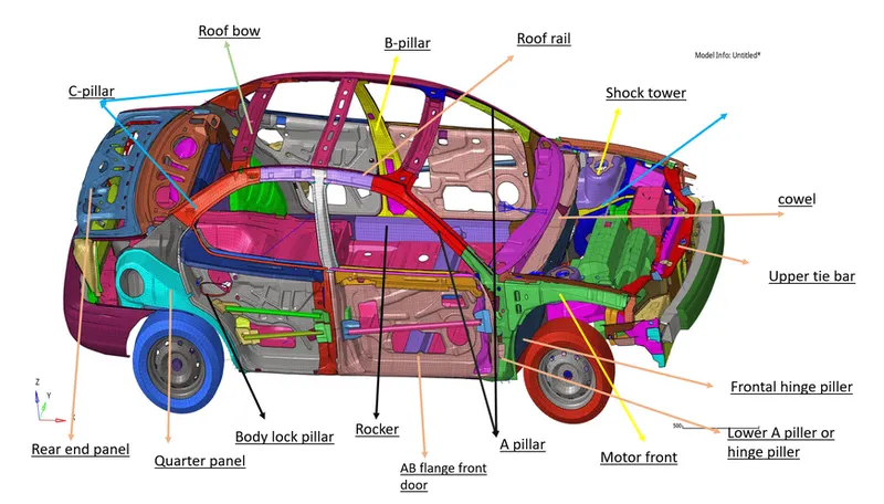
Parts :
A piller : Front Most support to the Roof .
B piller : Second most support to the Roof .
C piller : It is rear most support ; In case of the 2 seating system it wiil be 3rd one .
D piller : It is Forth support to the roof can be find the near rea side of quater panel .
Roof Header : Structural member above the windshield at the juncture with the forward edge of the roof panel .
Shotgun : Main structural Member of the BIW which absorb Crash energy , support battery and other parts , Transfer shock load from shock tower to Body .
Bumper : A horizontal bar Fixed at front and back side of the vehicle to reduce the damage in collision .
Rail : Located just behind the Bumper and absorb the crash energy after the Bumper .
Section : It is representation of the cross members of the vehicle .
Intrusion : Sudden Impact on the Body
Procedure :
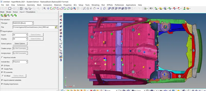
- The Neon Model is imported by setting the user profile For Radioss .
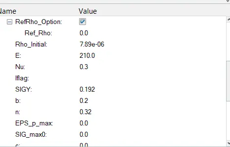
- The Unit system here we are following the KN , mm , ms , Kg , which can be seen from the Material parameters .
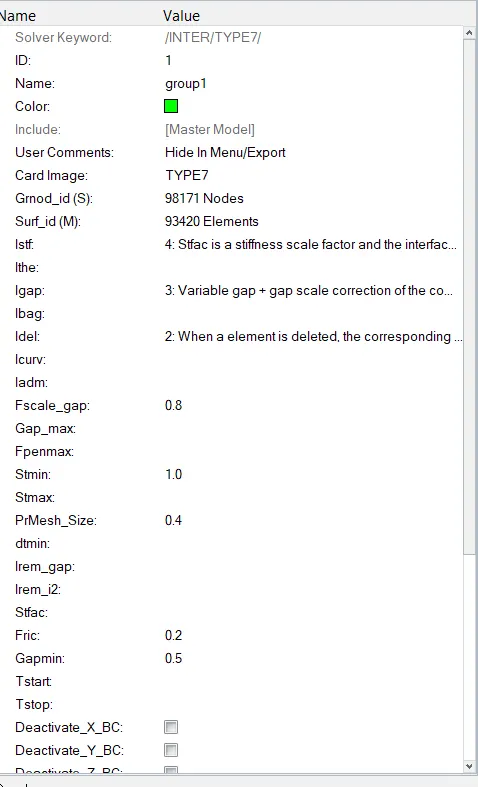
- Here we can see the extra Type 7 interfaces which will cause the simulation to run very slowly .
- Hence , I have deleted all the interfaces for each surface or part .
- Created only one Type 7 interface for all the Surface or parts .
- All the parameters are changed to the recomonded parameters .
- Changed Istf = 4 ,
- Igap = 3 ,
- Idel = 2 ,
- Fscale_gap = 0.8 ,
- Stmin = 1 KN/mm^2,
- % mesh_size = 0.4 ( default )
- Fric. = 0.2 ,
- Gapmin = 0.5 ,
- Iactiv = 6 ,
- Iform = 2 .
- This parameter can be seen below as ,
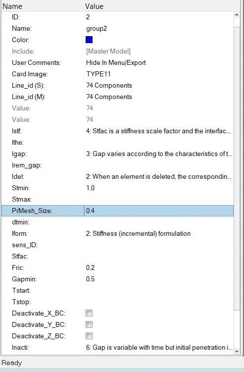
- Type 7 Interface can not tackle the edge to edge contact .
- For that Type 11 interface is also created to overcome the Edge to Edge Contacts .
- All the parameters are changedto the recommonded parameters .
- Now Checking is done for initial Penetrations and Intersections .
- This is done by Penetration checking Tool as ,
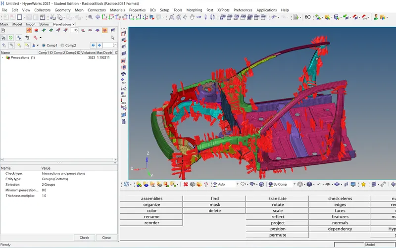
- For Fixing this Penetrations and Intersections , The Automatic Penetration / Intersection Fix Tool .
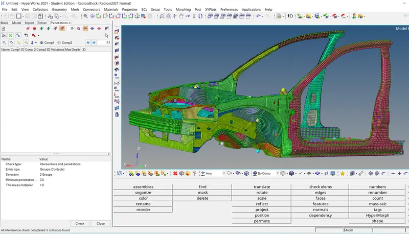
- Then Again initial penetration and the intersection is checked , as i have fixed the penetration by above method , which can be seen below .
- The Message with 0 penetration and the intersection can be seen in below image at left down side corner .
- Now Rigid wall is created with the Froction value of the 0.1 .
- Dsearch = 1000 ,
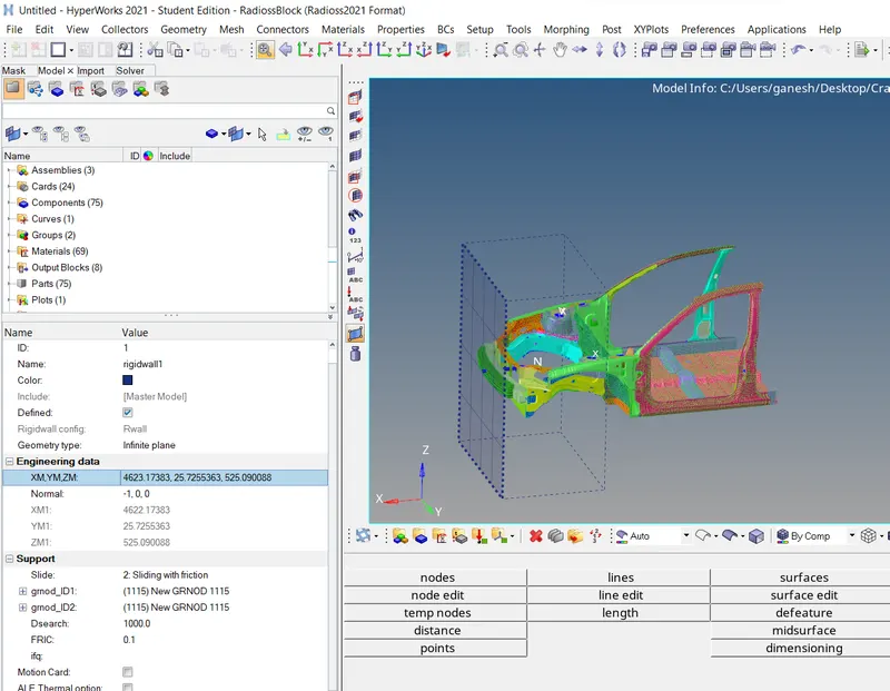
- After creating the Rigid Wall , i have cheched for the Center of Gravity .
- Initially this center of Gravity is present near and just below the dashbourd .
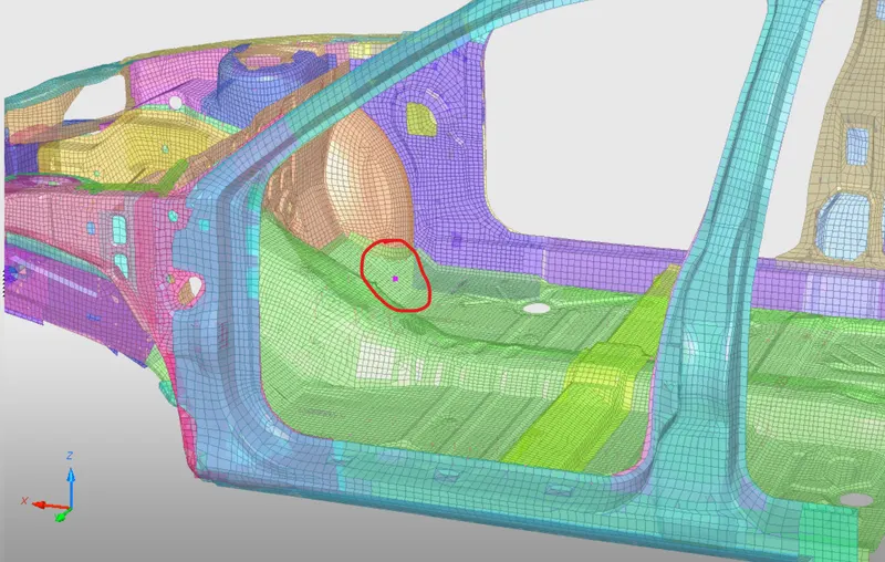
- A vehicle’s center of gravity, or CG, is the theoretical point where the sum of all of the masses of each of its individual components effectively act .
- Lower location of the Center of Gravity point is better from a handling standpoint, as it reduces weight transfer during cornering and braking, and it also reduces the propensity to roll over.
- The ideal location of Center of Gravity point should be below or near the drivers seat .
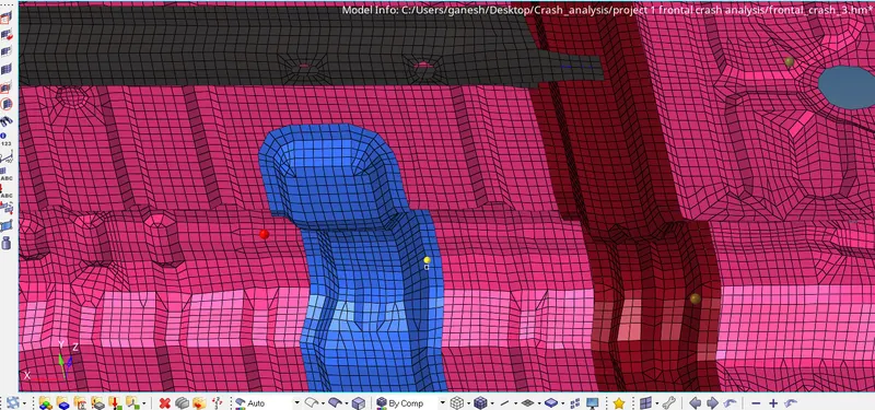
- For shifting this COG point towards the Idial Location i have added the Mass of Total mass of the 300 kg at rear end of the BIW body as shown in Below imgaes .
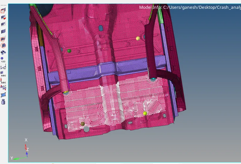
- For this Initially group of node is created at both left and right side seat's location .
- This using the ADMAS Tool , The mass type = 1 is selected .
- The Mass of 300 Kg will evenly distributed on each node .
- This Mass adding is helped lot for shifting the Center of Gravity point's Location .
- But In Hypermesh we can not see the Center of Gravity point directly .
- HyperMesh only show the Coordinates of the COG in X , Y and in Z direction .
- Using this Values , i have created the Teperary node as ,
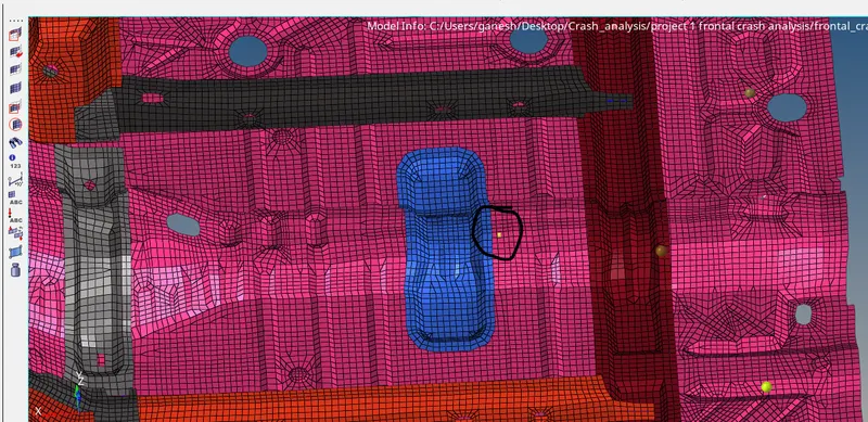
- To move this COG point near the Cross rail by small distance , to match with the Ideal location .The mass of Hand Brake is added at the cross rail location .
- And the Weight is of Rear Console also added , which is distributed evenly over all selected nodes .
- which moved the COG point by little distance .
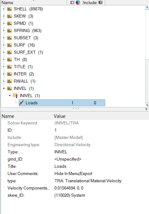
- Now Initial velocity is applied to all the parts by creating the INVEL card , in which the Type choosed as TRA = Translational Material Velocity .
- As we are folowing the milimeter and milisecond unit , hence initial velocity of 35 mph is converted to 0.01564694 milimeter/milisecond .
- For Skew id , newly created SKew System is used .
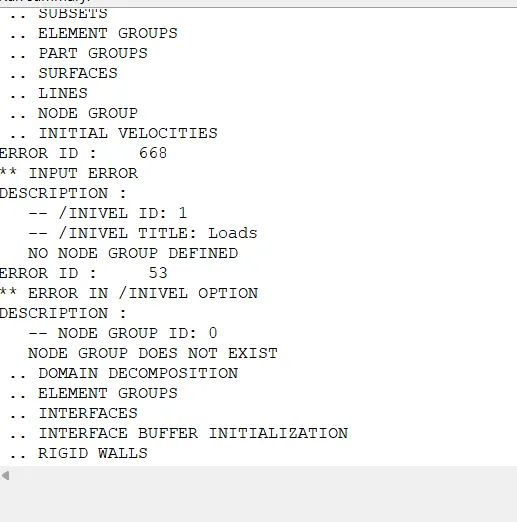
- While runing the simulation there was an Error Thrown regarding the Initial Velocity which can be seen below .
- This Error is resolve By defining the Group of Nodes .
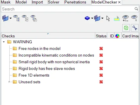
- Now Model checker is used to check the model's Quality .
- Now here we don't Got any Errors , but the Warnings only we got .
- This warnings just can be ignored for this model .
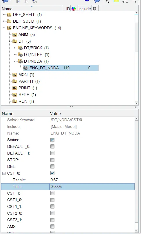
- Now time step of 0.5 microsecond is given .
- This time step is given in ENGNINE_KEWORDS - DT - DT_NODA CARD .
- Here CST ( Constant Step Time ) , this is used to maintain the COnstant time step my Adding the mass to model .
- HEre Tscale is Given as 0.67 and Tmin = 0.5 microsecond .
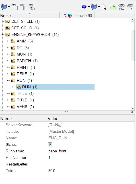
- Simulation run time is kept as 80 milisecond .
Output Request :
- For requesting the Sectional Forces in Rail Indicated Node Point 174247 at both side Left and Right , Group of Node is defined at Indicated node location and Using N1 , N2 , N3 points Reference is Defined as ,
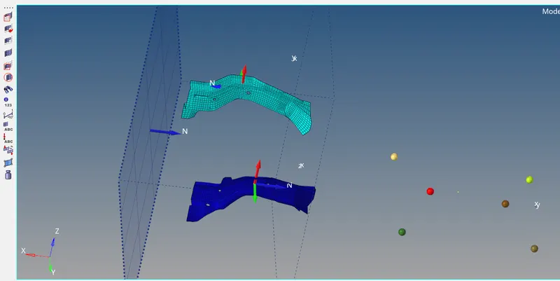
- Axial Force received on the rails from Bumper are difined by creating the Type 7 Contact interface between the Bumper and the rails on the both side left and Right side .
- bumper difined as Slave Nodes and rains nodes are defined as master nodes as ,
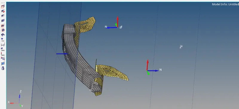
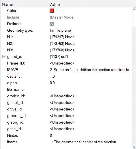
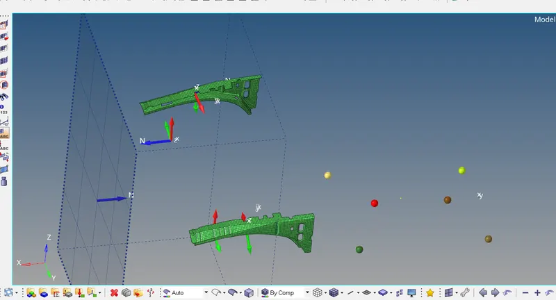
- Shotgun Cross sectional Forces are Defined Using Group of the nodes at appropriate location at both location left And Right , using Points N1 , N2 and N3 reference is defined as ,
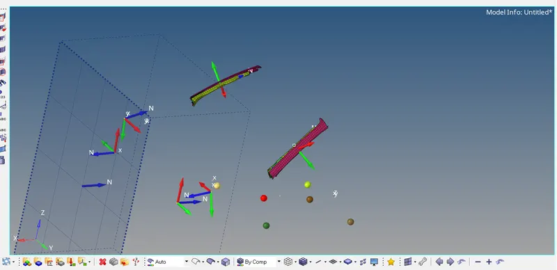
- For getting the Force at A piller , Section is created unig the group of the nodes and with the N1 , N2 and N3 reference is also defined on the Both sides as,
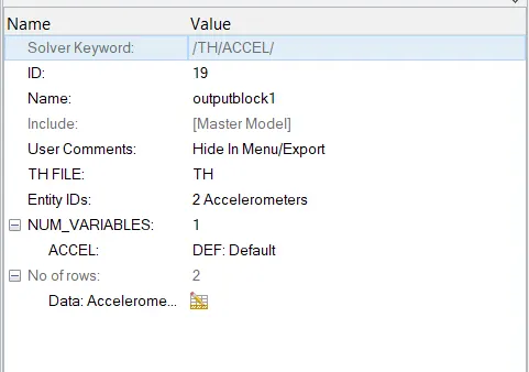
- For getting the Accelerometer Curve , i have created the accelerometer at the Rocker part of B piller on both side as ,
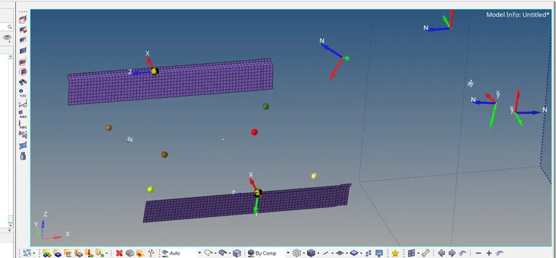
- For getting this accelerometer output in Time history , TH card is also Created ,
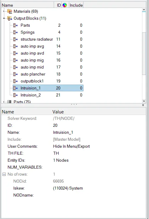
- Intrusion at Node 66695 and the 66244 created with the Reference of New skew system as ,
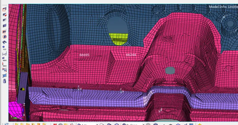
Now Model is ready to run :
- Now Model is made to run In Radioss Solver and Simulated using the HyperView .
- The Energies plots are plotted using the HyperGraph2D .
Results :
Energies :
- From graph is can be seen that the Kinetic Energy is High at Starting Of crash and decrease after the crash happens .
- The Kinetice Energy decreases with increase in the internal energy .
- This kinetic Energy is get converted into the Internal Energy .
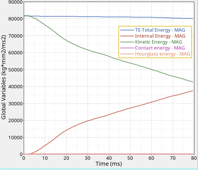
- The Hourglass energy is in the range of the 5 % of the Total Energy .
- This hourglass energy is much stabalized as we have improved the shell properties to the recommonded .
- The Total energy is Almost Constant , which is Good Sign of Energies Balance .
Setion forces at Given Node:
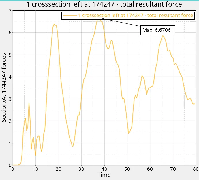
At 174247 left :
At Right Side :
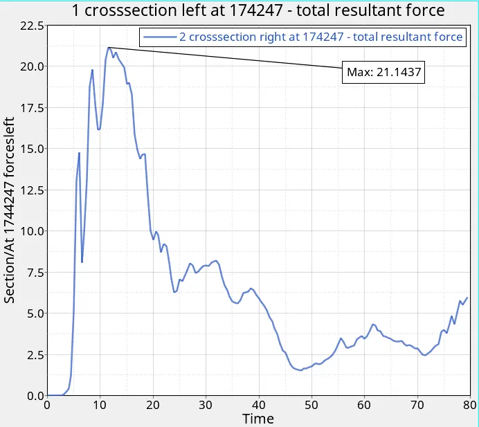
- Maximum Force Right side of the indicated node location is observed 21.147KN and on Left side is 6.67 KN .
- More Force observed on right side is because of the Weight Distribution , as force directly propertional to the Mass .
- Hence more force is travelled through the right side .
Axial Forces at the Rails :
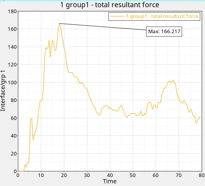
- The axial forces are the force Which are get transfer from the Bumper to the Rails .
- When Crash happens , Force generated into the Bumper are get transfer to the Rails and This forces are firther transfed to the Next sections and parts .
- The maximum force we are getting at the rails form bumper is 166.217 KN .
Shotgun Forces :
Left : Right :
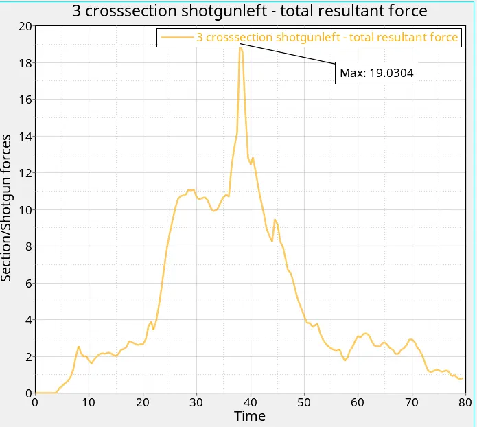
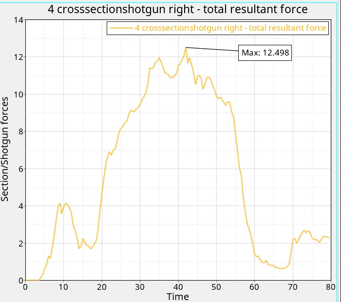
- The Forces in shotgun section are come from the frontal rails , which are then transfer further and Some part of the Absorbed here .
- The maximum force is passing through the left Shotgun section is 19.0304 KN than the right Shotgun section is 12.498 KN .
- Here the Less Force is absorbed than the rails and other frontal parts .
- Uneven distribution of the Force passing through the Shotgun section is because of the Uneven distribution of the Mass .
A piller Forces :
Left Piller : Right Piller :
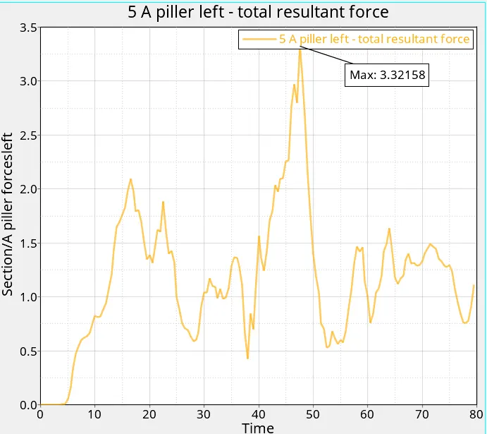
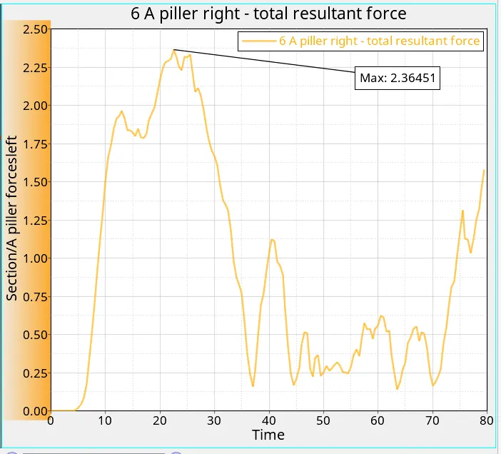
- The Residual forces from the Frontal Parts are absorbed in the A piller Section .
- The Forces Passing through the Left and right A pillers are 3.32158 KN and 2.36451 KN .
- The Forces through the A piller Decides the damage to the Occupants in Vehicles .
- More the Force More will be the damage to Occupants .
Intrusion At Dashboard :
- Intrusion means the sudden change in space located for the feet of the occupants in vehilce .
- This Intrusion Matters the most in term of the Occupant's saftey .
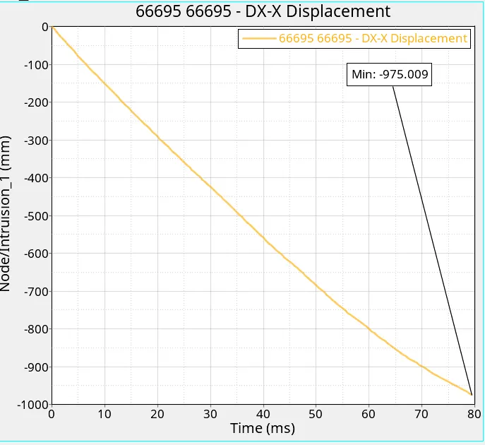
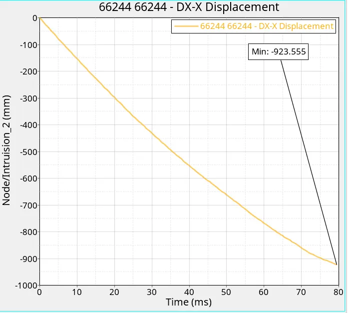
- Intrusion at 1st indicated nodes is _975.009 mm and at 2nd node is -923.555 mm .
- The Negative sign indicates the intrusion happening in the Negative X-axis direction .
Errors :
After assigning the Condition and creating the sections , while analysing the model using the Radioss Solver .
There was an Error thrown , regarding the Initial velocity That the , there is no group of nodes was defined .
This Error is rectifed by defining the Group of the nodes .
And again Model is analysed by the Radioss and it analysed Any Errors but with some wanrnins which can be ignored .
Conclusions :
- For proper crash results , the Mass distributions Matters the most .
- The forces from the bumper are transfered to the further parts and distributed over other parts depending upon the BIW structure of the vehicles .
- most of the Forces are absorbed at the Bumper level after the crash of the vehicle .
- Followed by the Rails .
- This Rails and followed parts are designed in such way that they should absorb most of all the forces resulted due to the Crash of the vehicle.
- The Intrusion at the Dashboard should be less as possible .
- This Intrusion plays an important roles in the Occupants Saftey.
- More the forces passes trough the section / parts from fornt side to back side More will be the dangerous for the Occupants .