Assignment 6-Frontal Crash Simulation Challenge
Question:
Frontal crash-BIW
- Check unit system and either follow[Mg mm s] or [Kg mm ms].
- Create appropriate interface ,friction 0.2 and recommended parameters.
- Make sure of no penetrations and intersection.
- Correct rigid bodies if any issues.
- Create rigid wall with friction 0.1.
- Compare the model weight with the full scale 300k nodes model and use added masses to reach target weight 700kg while getting CG about the required range.
- Initial velocity 35 mph.
- Use model checker to ensure good quality.
- Time-step :0.5 to 0.1 microseconds.
- Run 80 ms.
Output requests:
- Sectional force in the rails at location of indicated node 174247.
- Axial force received on the rails from bumper.
- Shotgun cross sectional forces.
- A pillar cross section.
- Acceleration curve received on the accelerometer at base of B pillar (on B pillar rocker).
- Intrusions on the dash wall 66695,66244.
Aim:
To set up the given simulation conditions on the BIW model for frontal crash simulation in HyperMesh/RADIOSS and discuss the results obtained.
Procedure:
The model is imported using the import option in the hypercrash.
The unit system is checked in the rad file and it is found to be kg mm ms.
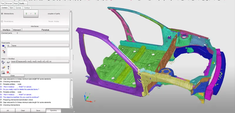
Using added mass option in the hypercrash additional mass is added for the passenger, driver and trunk portion of the car and the total mass of about 700kg is achieved and the COG point is placed properly.
- Now we have to align CG to the centre of the car so for that we have to add the wieght to the accordingly.
- So see the Mass of the car go to the TOOLS>MASS DETAILS
- Now we will go to hypercrash to balance the Mass. For that go to MASS>BALANCING
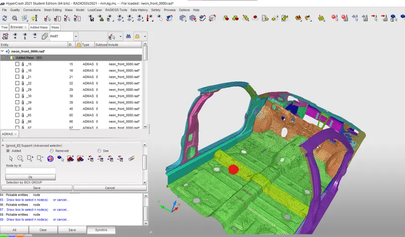
So to add the mass in we have to keep in mind that component should not exceed more that 700 kg.To add the mass in go to the BROWSER>CREATE NEW > ADDED MASS and add the masses accordingly.
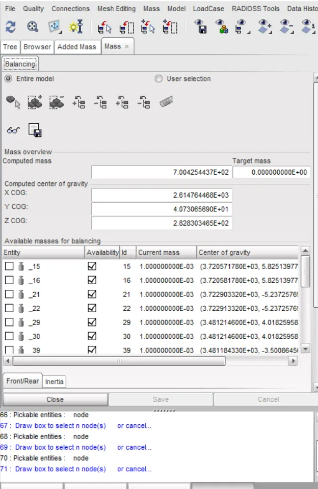
Now in this we can see the the COG is align at the center and the mass of the car is not exceeding 700kg.
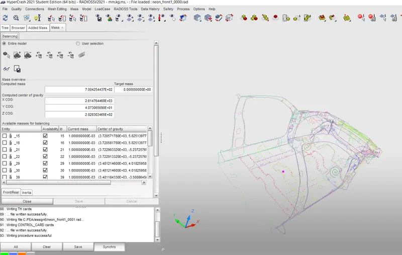
Then the model is exported to the hypermesh using the export option.Then the model is imported in the hypermesh using the import option in the hypermesh.
TYPE 7: NODE TO SURFACE
This interface simulates the most general type of contacts and impacts. TYPE7 interface has the following properties:
1. Impacts occur between a master surface and a set of slave nodes, similar to the TYPE5 interface.
2. A node can impact one or more master segments.
3. A node can impact on either side of a master surface.
4. Each slave node can impact each master segment except if it is connected to this segment.
5. A node can belong to a master surface and a set of slave nodes.
6. A node can impact the edge and corners of a master segment. None of the previous interfaces allows this.
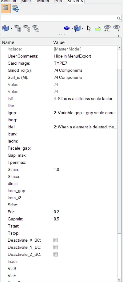
The recommended properties are as following:
1.Igap = 2 (Variable Gap took into account.)
2.Gapmin ≥ 0.5mm (minimum thickness to avoid the numerical issue.)
3.Inacti = 6 (remove initial penetrations wherever possible, else reduce to less than 30% of the defined gap)
4.Istf = 4 (Stiffness based on softer Segment)
5.Stmin = 1 kN/mm (Minimum stiffness in contact to avoid too soft contact.)
6.Idel = 2 (remove slave nodes from contact because of element deletion)
7.Iform = 2 (Frictional Forces are calculated on the basis of Stiffness parameter.)
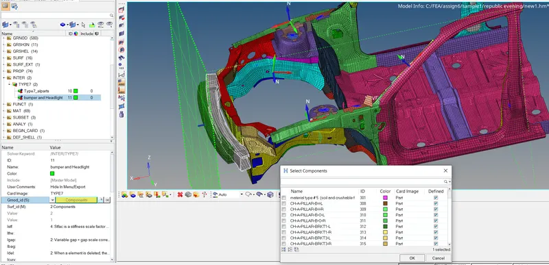
Delete existing contacts and create new contacts with recommended properties.
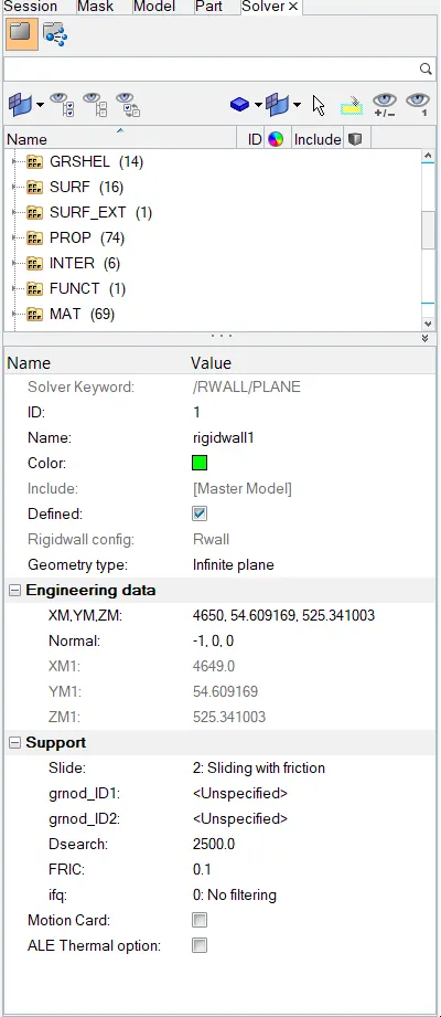
Create Rigid wall with friction 0.1:-
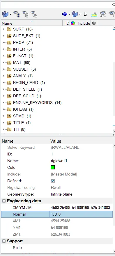
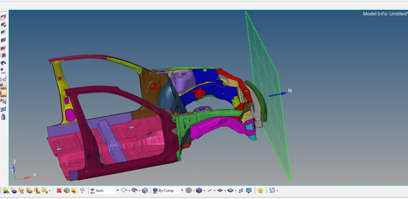
For this we will go to the SOLVER>CREATE>RWALL and then creat a Plane wall with friction 0.1 as shown:
- A rigid wall is a nodal constraint applied to a set of slave nodes in order to avoid the node penetration to the wall. If contact is detected, then the slave.
- Node acceleration and velocity are modified. Mainly to constrain the movement of a moving body after impact, we will be using a plane wall. An infinite plane wall is a plane that extends to infinity. It is defined with two points.
- Rigid wall entities provide a method for treating a contact between a rigid surface and nodal points of a deformable body.
- Initially, a node is created and it is translated to some distance and using this node coordinate as a reference, the rigid wall is created.
Create INVEL:
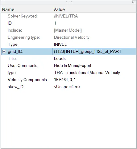
Initial velocity 35 mph.
To create intial velocity first we will convert 35 mph to ms
35 mph = 15.64 m/s
Now to create INVEL card go to the BROWSER>BCS>INVEL.
Then add the value and create the card as shown:
Sectional force :
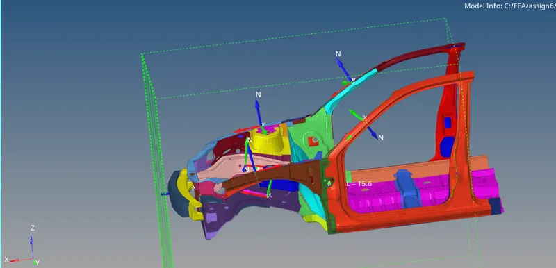
- Creation of Sections at A-Pillar, Shot Gun, rails and the Bumper in order to Study the sectional forces.
- We have to know how the forces are transmitted from the Bumper to the Dashboard and the rate of deformation. It is done in order to ensure the safety of the passenger.
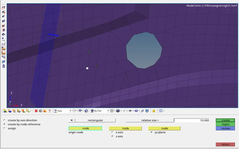
- Certain components have to crash (deform) more than the other so that the forces are distributed correctly leaving very little force left to transmit inside the cabin.
- We are creating sections for the following parts.
- i. Left Rail
ii. Right Rail
iii. Left A-Pillar
iv. Right A-Pillar
v. Right Shotgun
vi. Left Shotgun
CREATE ACCELERATION NODES:
- Creating Accelerometer at both sides of the B pillar.
- An accelerometer is a basic technology that converts mechanical motion into an electrical signal. It is an electromechanical device that measures acceleration forces, whether caused by gravity or motion.
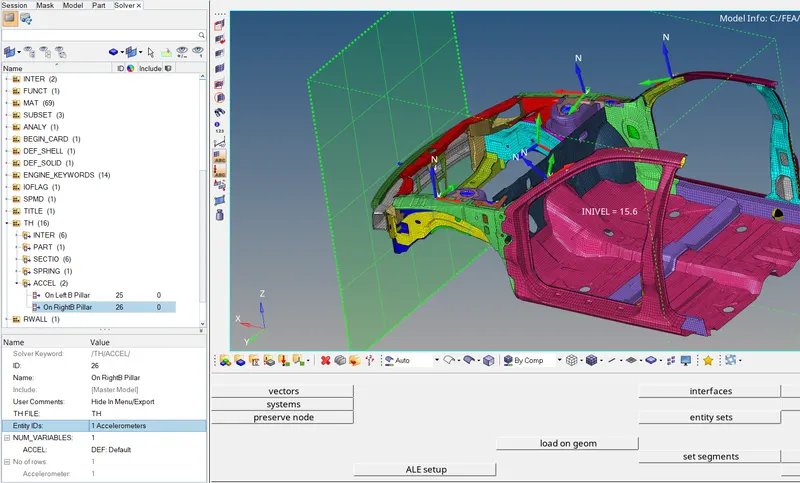
- To create accelerometer.
- Go to Model browser >> Create >> Accelerometer >> Select Node_ID >> Select node >> Proceed.
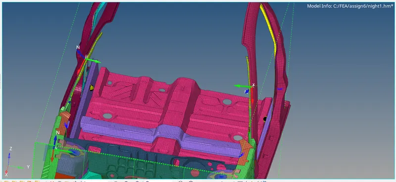
REQUESTING TH FOR INTRUSION SPRINGS, ACCELEROMETER, SECTION FORCE:
- Delete existing TH and create new.
- They are Output files that are requested in the Starter File.
- All the Global variables (Internal energy, Kinetic energy, Contact Energy, Hourglass Energy, etc.) are already requested by default.
- We have to call for additional Time History files for the boundary conditions that we have created for the frontal crash model.
We can create the Output requests from within the Solver Browser:
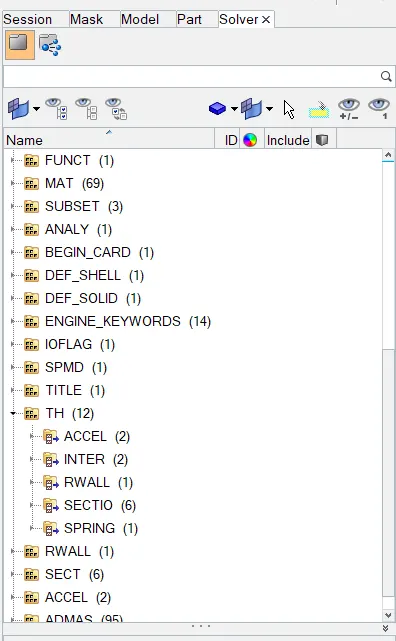
Solver Browser > Right Click > Create > TH > Select the Output Request.
Output Requests Boundary Conditions
INTER
i. Self Impact
ii. Left Bumper and headlight
iii. Right Bumper & headlight
ACCEL
i. On Left B Pillar
ii. On Right B Pillar
SPRING
i. Intrusion on node 66244
ii. Intrusion on node 66695
RWALL
i. Rigid Wall
SECTION
i. Left Rail
ii. Right Rail
iii. Left A-Pillar
iv. Right A-Pillar
v. Right Shotgun
vi. Left Shotgun
To create TH
Go to Slover browser >> Right click >> Create >> TH >> Select section for Sectional forces >> ok.
Now we will Run the simulation.For this go to the ANALYSIS>RADIOSS
Out file:
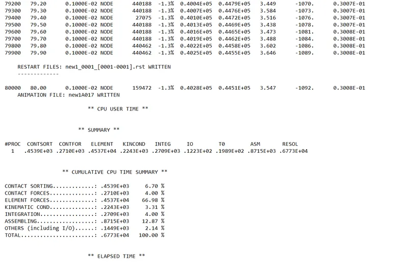
The Energy Error is Negative and it is in the range -1.4% to 0.8% which is acceptable.
Mass error is 0.014 to 0.038 which is acceptable.
We can conclude that there are no errors in the analysis.
Review the Simulation:
We have to import the animation file in HyperView first:
HyperView >> FIRST_RUN. h3d >> Apply
1. The tools to review the simulation are available on HyperView.
2. HyperView is a post-processing and visualization environment for FEA that gives the output of the analysis in a simulations format that is user friendly to
understand.
3. From the simulation, we can review how the impact force acts and causes deformations and point of rupture on the model.
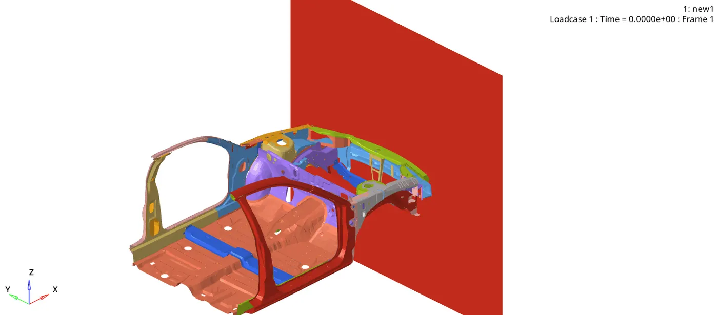
Now switch to the HyeprView and open .h3d file.
It will look as shown below:
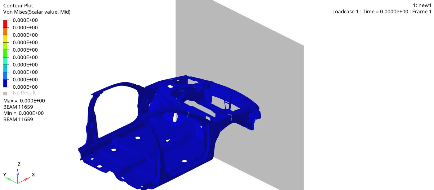
Vonmises:
PLOTTING GRAPHS:
Now for this we will open T01 file in HyperGraph2D
The graphs of requeste output as shown below:
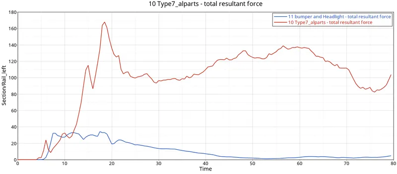
RAILS 1 and 2
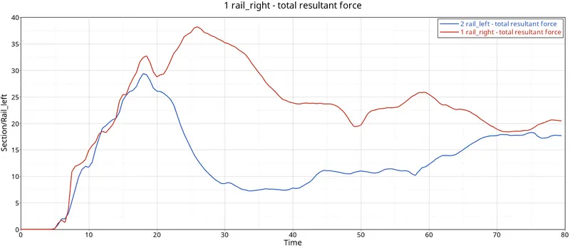
Here you can see the peak time of the both sections is almost same but the C/S of Rail_left having resultant force is 47KN/mm is more that Rail_right having resultant force is 30KN/mm.
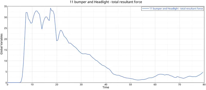
BUMPER 1 and 2
SHOTGUN 1 and 2
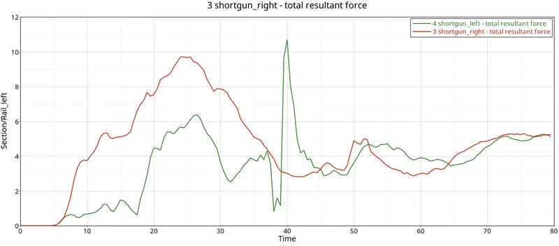
The force in the right Short gun right is more linear compared to the sharp hills in the left Short gun left.
The maximum cross-sectional total resultant force at Shotgun right is 10 kN/mm at t=25ms whereas the maximum cross-sectional total resultant force at Shotgun left is 6.5kN/mm at t=25ms.
PILLAR 1 and 2:
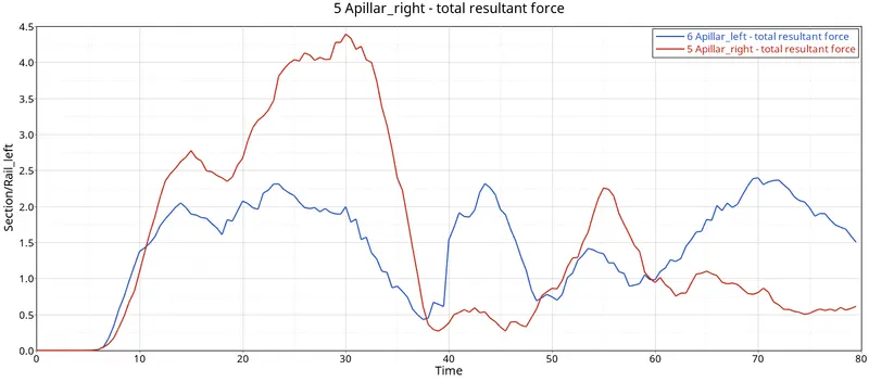
Pillar has maximum toalt resultant force of 6.2KN whereas pillar 2 has maximum total resultant force of 4KN. Hence, the normal forces are not significant.
ACCELARATION:
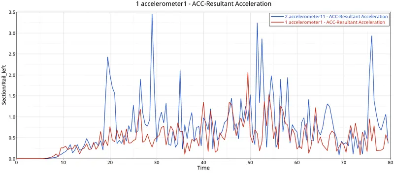
Accelaration of the 1st point is less fluctuating that the 2nd.
RWALL
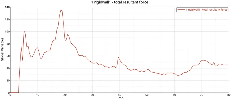
The peak point shown where the car hit on the wall at maximum force which is 140KN at 15ms.
INTERFACE
1 RAILS 1 and 2
1. 47 KN
2. 27KN
2 BUMPER 1 and 2
1. 35KN
3 SHOTGUN 1 and 2
1. 10KN
2. 8.5KN
4 PILLAR 1 and 2
1. 4.5 KN
2. 2.5 KN
5 ACCELARATION
1. 3.5 KN
2. 2.0 KN
7 RWALL 140KN
8 INTERFACE 160KN
1. Learned how to set up a frontal crash test.
2. Learned how the Rigid wall interface works and can lead to incompatible Kinematic conditions.
3. Learned how Sectional forces are generated.
4. Learned how the distribution of forces among the components during a frontal crash.
5. Learned how some components are designed to deform in such a way to ensure the safety of the passengers inside the cabin.
6. Learned how to check for Energy, mass, and momentum balance.
7. Learned how to Debugging errors in order to get the right results.
OBSERVATION:
We saw in the animation that the most deformation took place in the frontal area and the stress is then passed to the rest of the components of the car.
We observed that the impact of the crash is taking mostly at the frontal region of the car and by looking at this we can say that the setting area of the
driver and passenger will be also impacted which can cause injury to them.
CONCLUSION:
The car crash was simulated onto a rigid wall and the various forces, accelerations and displacements were plotted, tabulated and discussed. Points were also made to potentially improve the quality of the simulation in future. From the simulation, it can be observed that there was minimum deformation in the cabin, and also minimum intrusion was found in the driver’s seat area.