Assignment 2-RADIOSS Engine File Editing & 3D Meshing Challenge
Aim :-
- To edit the Engine file and 3d meshing the given components.
Procedure:-
- Check the material properties of the rail component and calculate the speed of sound in steel rail =
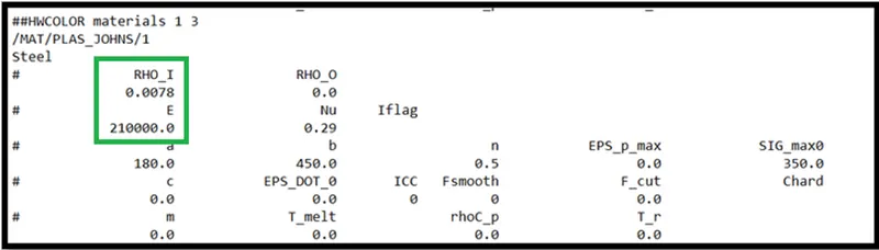
From the "FIRST_RUN_0000" we can get the values of steel material is ,
Young's modulus of material is 210000.0 = 210GPa
Density is 0.0078 which is equal to 7800 kg/m3
we know that, Speed of sound in the material is (c)
`root`(E/D) = `root`(210GPa/7800) = 5188.74m/s or 5188.74mm/ms
2.The length of the rail is about 1000mm .Calculate the time takes for a shock wave to travel from one end of the rail to the other.
Time takes to shock wave to travel 1000mm = L / c
Where, L is length of rail
C is speed of sound in material
= 1000/5188.74
t = 0.192725ms
3.Time for sound to travel the length of the rail.
Time taken by the sound in the material medium = 0.192725ms
4.Edit the engine file so that the stress wave can be monitored, moving from one end of the rail to the other during impact -this will require a termination time equal to the time it takes for the sound to travel the length of the rail(set on/RUN card).
First, I have imported the FIRST_RUN_0000.rad by import solver deck option. Engine file is FIRST_RUN_0001.rad.
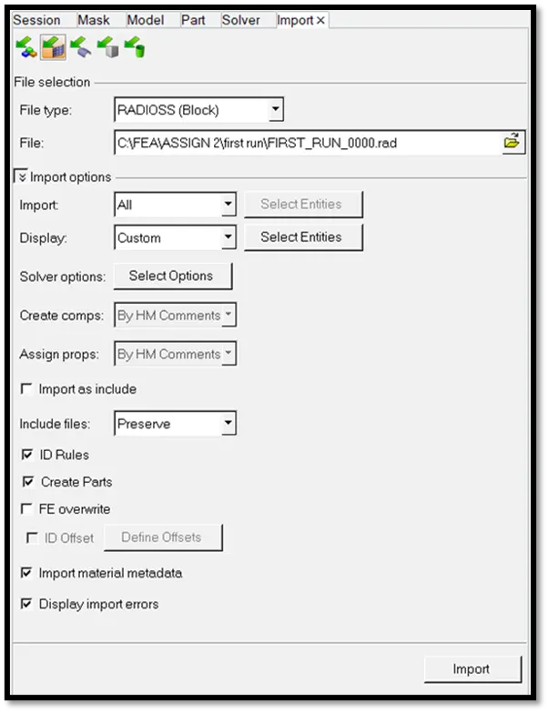
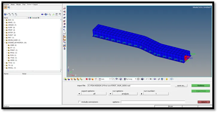
Now, in the solver we can edit the values of the Engine run time by clicking on the ENG_RUN and changing the value to 0.1927.
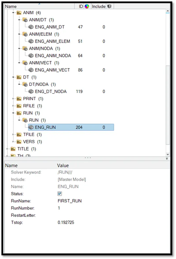
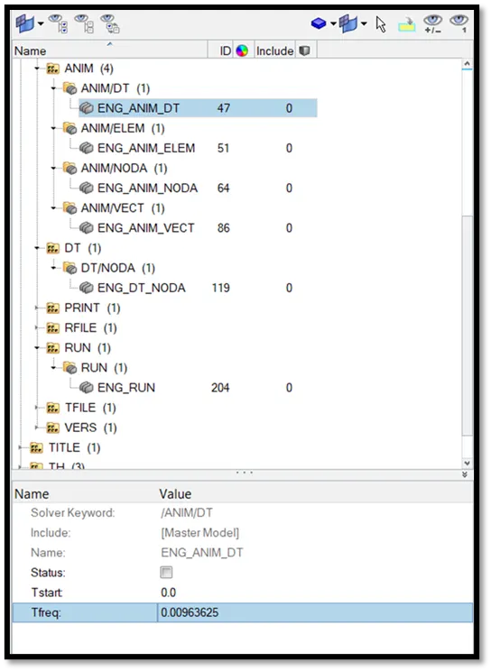
5.Set the frequency of animation output to a time that will give 20 animation steps(/ANIM/DT)
To get the 20 animation frames we have to change the Tfreq in ENG_ANIM_DT as,
Animation steps = 20
Run Time = 0.1927
= 0.192725ms/20
=0.00963625
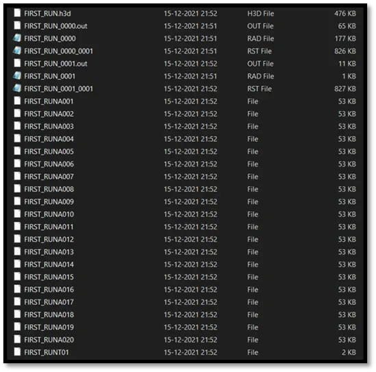
In the out folder we can observe the number animation file are reduced to the 20. Animation files are with the name “FIRST_RUNA000”.
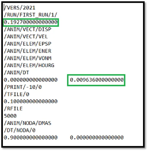
The final edited Engine rad file is,
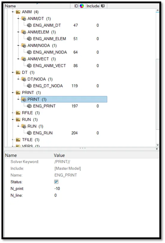
6.Change /print -10.
We can change the Print value to -10. It means it will print the values for every 10 values while the solver is running.
7.3d meshing tetra mesh and hex mesh.
- Repeat class examples and, maintain the quality.
- Target tet size=5mm,hex size=10mm,tet collapse=0.15.
Procedure –
Step 1 : importing the given STEP file into the hypermesh.
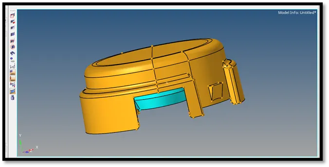
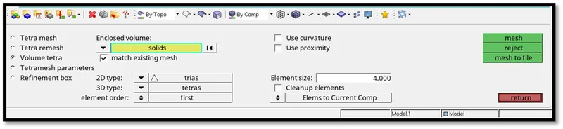
Step 2 : After checking the geometry and doing the edits. Go to 3d panel and choose the Tetra mesh > Volume tetra > select the 2 solids in the model. Set the element size as 5 and click on mesh.
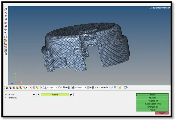
Step 3 :- We can get the tetrahedral mesh as shown in the image. We can observe the mesh flow by using the mask feature.
- Arm Bracket Model.
Step 1: Importing the given STEP file into the hyper mesh.
Step 2: meshing of base component
- First 2d mesh on the top surface by using the automesh.
- Next by using the element offset method we can mesh it in 3d.
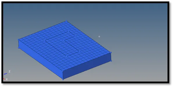
- By this we can create the hexa elements mesh for base.
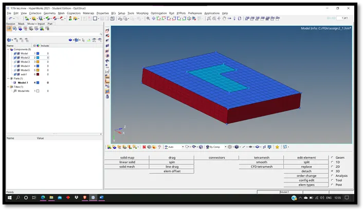
Step 3: meshing the middle components
- We can use the spin option in 3d meshing for that create a base node by using the circle centre option for the arc.
- Set angle to 90 and on spin to 25.
- Click on Spin-, Hexa mesh is created.
- For, meshing of other part we can use Linear solid in 3d panel.
- We need to have the same number of elements on both the surfaces for that.
- Select the from and to elements. Alignment of nodes on both surfaces.
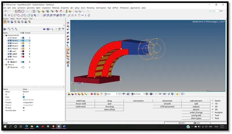
Step 4: meshing of bose component.
- First mesh the top surface by using the automesh. Edit it for good mesh flow.
- Now use the solid map tool for 3d hexa mesh. Before project the nodes on the on the components to maintain the connectivity of two components.
- delet the all the 2d meshing faces that we have created while meshing by using the delet faces option.
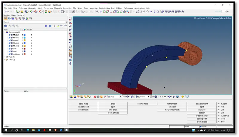
Final CAD Model image.
Objectives of learning from the Assignment :
- Learnt using different options in 3d panel of hyper mesh for 3d meshing.
- Editing of Engine file of Radiosis solver.
- Equations of shock wave traveling in the materail medium.