Assignment 6-Frontal Crash Simulation Challenge
Aim:
Frontal crash-BIW
- Check unit system and either follow[Mg mm s] or [Kg mm ms].
- Create an appropriate interface, friction 0.2 and recommended parameters.
- Make sure of no penetrations and intersections.
- Correct rigid bodies if any issues.
- Create a rigid wall with friction 0.1.
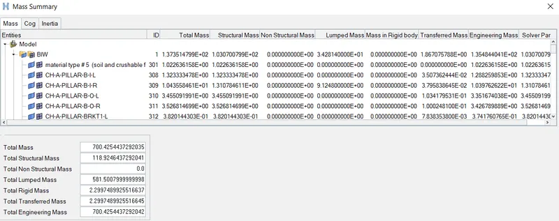
- Compare the model weight with the full-scale 300k nodes model and use added masses to reach the target weight of 700kg while getting CG about the required range.
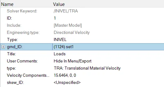
- Initial velocity 35 mph.
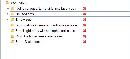
- Use a model checker to ensure good quality.
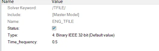
- Time-step :0.5 to 0.1 microseconds.
- Run 80 ms.
Case 1: Check unit system and either follow[Mg mm s] or [Kg mm ms]
The unit system is determined using the Radioss Starter file.

Case 2: Create an appropriate interface, friction 0.2 and recommended parameters.
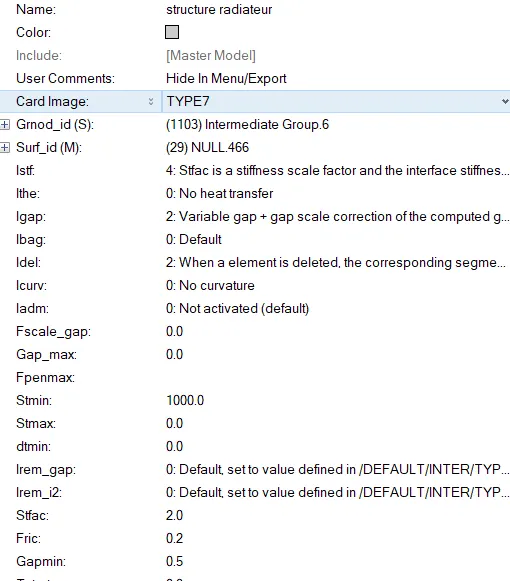
All the given contacts were modified and the recommended values were defined in the contact with Fric =0.2
Case 3: Make sure of no penetrations and intersections.
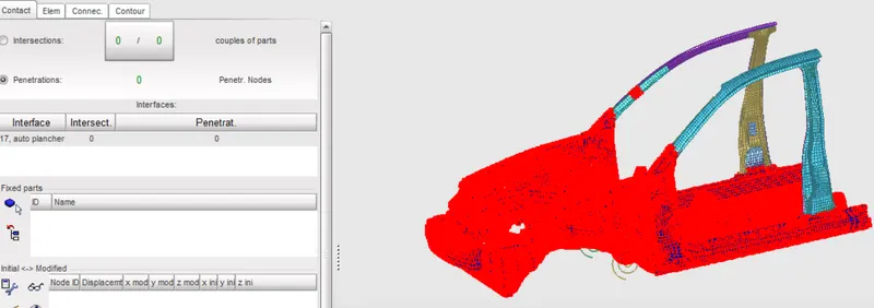
Using the Contact Interface option under the LoadCase option, the complete body was selected and the penetration check was established. No Penetration and Intersection was determined in the model.
Case 4: Correct rigid bodies if any issues.
Case 5:Create a rigid wall with friction 0.1.
Case 6:Compare the model weight with the full-scale 300k nodes model and use added masses to reach the target weight of 700kg while getting CG about the required range.
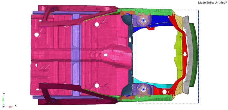
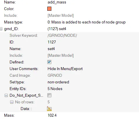
Add Mass option was utilised and 102.4kg of mass was added to 5 nodes across the region to bring the cg location close to the driver location.
Case 7: Initial velocity 35 mph - on converting mph to mm/ms it was found that the obtained velocity was about 15.64mm/ms.
Case 8:Use a model checker to ensure good quality.
Case 9:Time-step :0.5 to 0.1 microseconds.
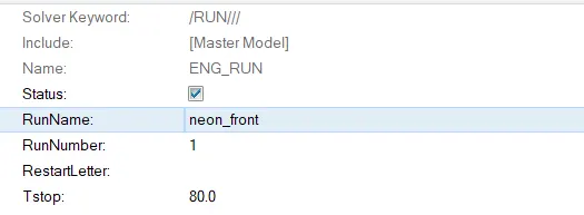
Case 10:Run 80 ms.
RESULT:
Output requests:
- Sectional force in the rails at the location of indicated node 174247.
- The axial force received on the rails from the bumper.
- Shotgun cross-sectional forces.
- A pillar cross-section.
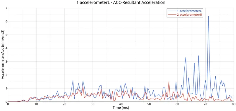
- Acceleration curve received on the accelerometer at base of B pillar (on B pillar rocker).
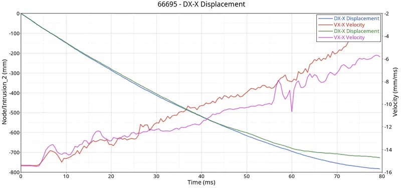
- Intrusions on the dash wall 66695,66244.
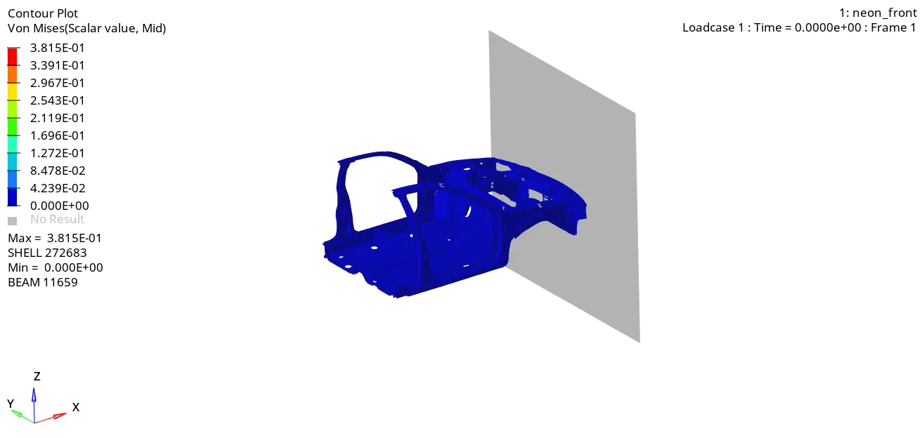
Fig: Von Mises Stresses distribution
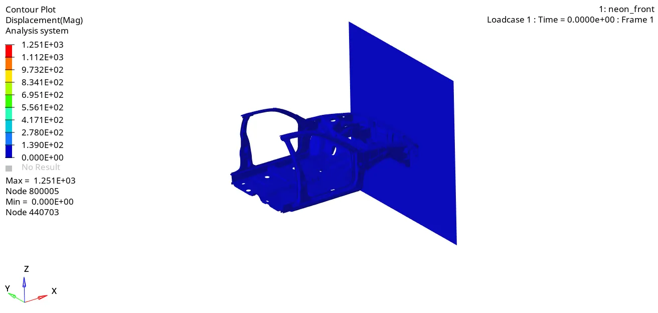
Fig: Displacement Contour
Shotgun cross-sectional forces
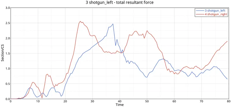
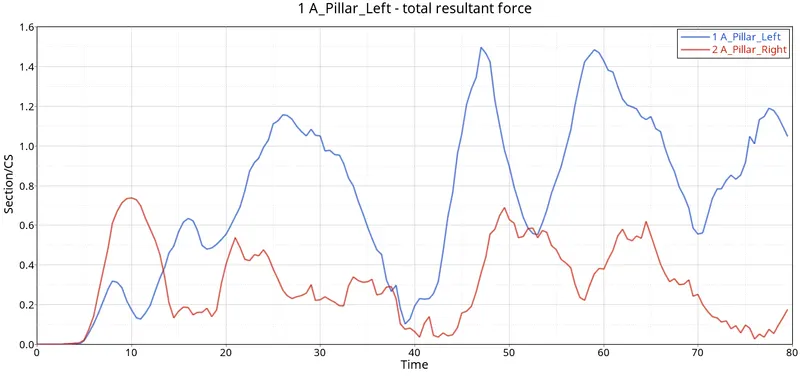
A pillar cross-section
Max Force on A Piller Left = 1.496kN at 47ms
Max Force on A Piller Right = 0.739kN at 9.5ms
Acceleration curve received on the accelerometer at base of B pillar (on B pillar rocker) - maximum acceleration of 6.387`(mm)/(ms^2)` was observed in the left side of the specimen.
Intrusions on the dash wall 66695,66244
Conclusion
According to the given condition, the simulation is carried out and the required results were obtained. From the obtained results, the following observations were made:
- Due to the impact, the maximum stress of 381 MPa was generated on the structure.
- Results from the A-pillar (right) cross-section represented that a total resultant force of 739N was obtained at 9.5ms whereas a higher maximum force was obtained in the A-pillar (left).
- The resultant force, maximum acceleration was obtained in the left section of the B-pillar.