Assignment 5-RADIOSS Interfaces & Study of Effect of Notches Challenge
Aim : Create the mesh for bumper assembly,mesh size should be 6mm.
- Run the crash tube model as it is.
- Change the Inacti=6 and run.
- Create the type 11 contact and run.
- Remove both notches and remove boundary condition on rigid body node then run.
- Create a new notch in the middle ,select the whole section and run.
- Create a new notch with nodes only from opposing 2 faces and run.
Note:
- Plot RWALL forces ,contact forces,internal energy and Create TH/PART for all parts and compare results for all cases.
- Comment your thought on why there is a change in the internal energies.
- How does the notch affect the results?
- Plot energies and note any difference
Solution : Meshing of Bumper Assembly.
For this .hm file is provided so no need to import geometry.
Clean the geometry and join the flanges as the flanges were open.
Meshing : Goto 2Dmesh - Automesh - select the element size as 6 - mesh.
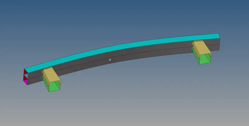
Now connecting these part with proper connector.
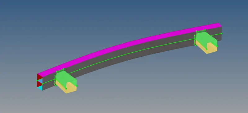
I have used spot weld for connecting crash box upper and lower and rest Seam weld.
Goto Connector - Seam Weld - provide the appropriate values.

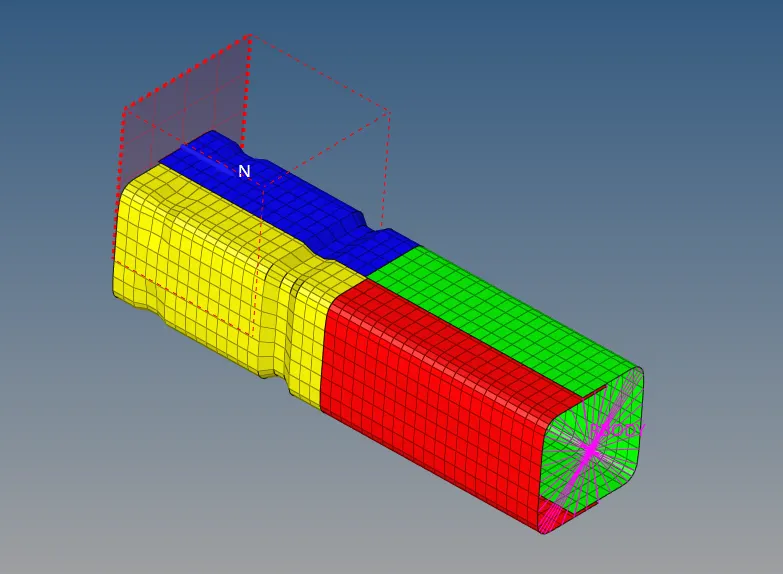
Import the Crash Tube model by import solver deck.
Run the crash tube model as it is.
Iteration:1
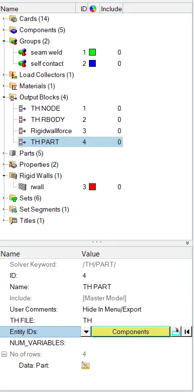
Create a THPART - Goto Outlook - right click create. In Enitity ID select component and select all the components.
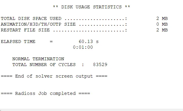
Now to simulate the Model Goto Analysis - Radioss.

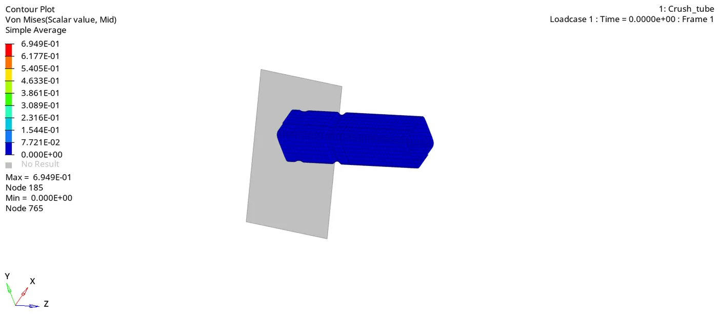
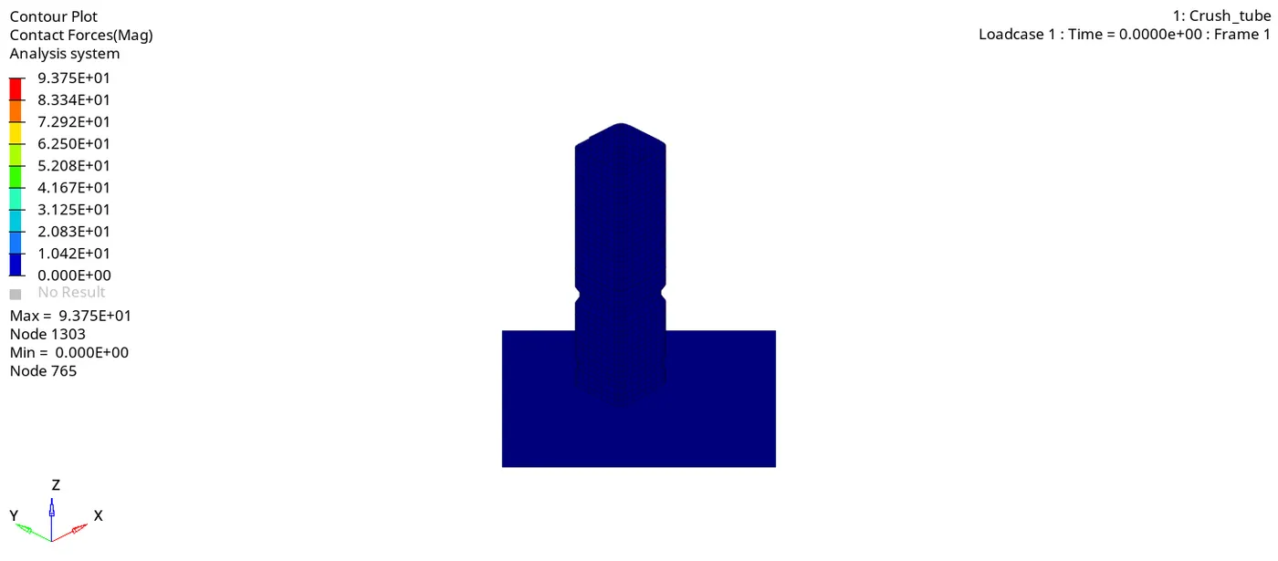
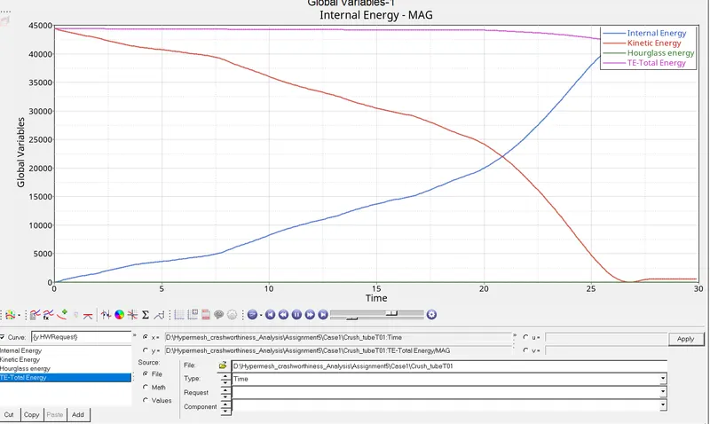
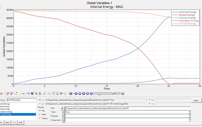
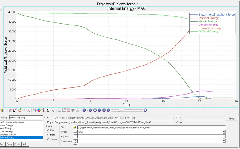
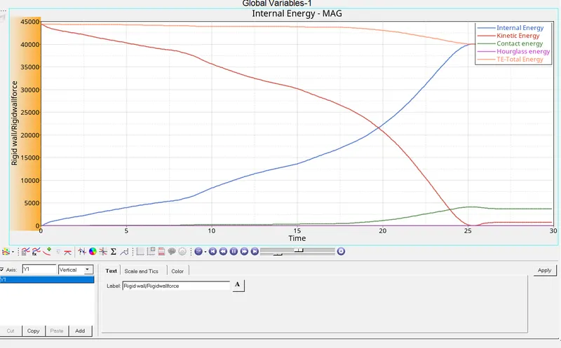
Internal Energy is gradually increasing and Kinetic energy is dropping to zero after 25ms. Hourglass is zero and total energy is constant until 20ms and then drops slightly.
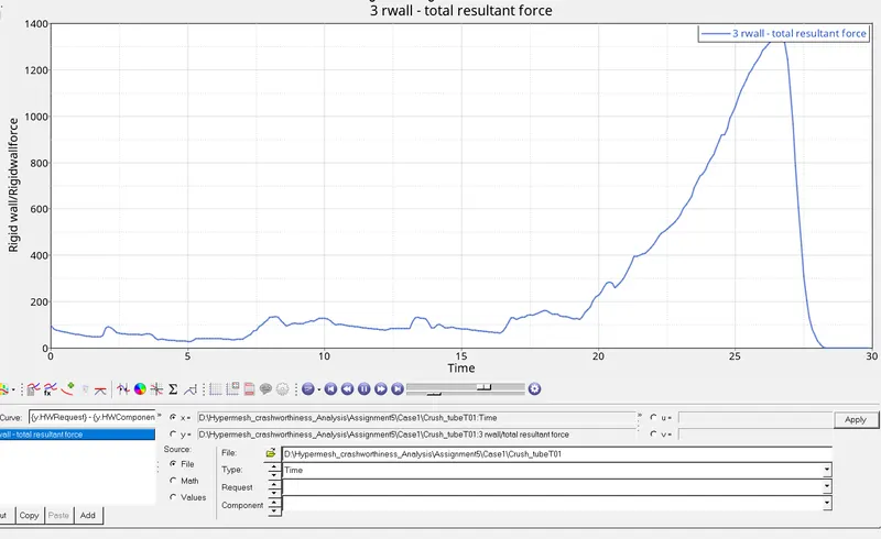
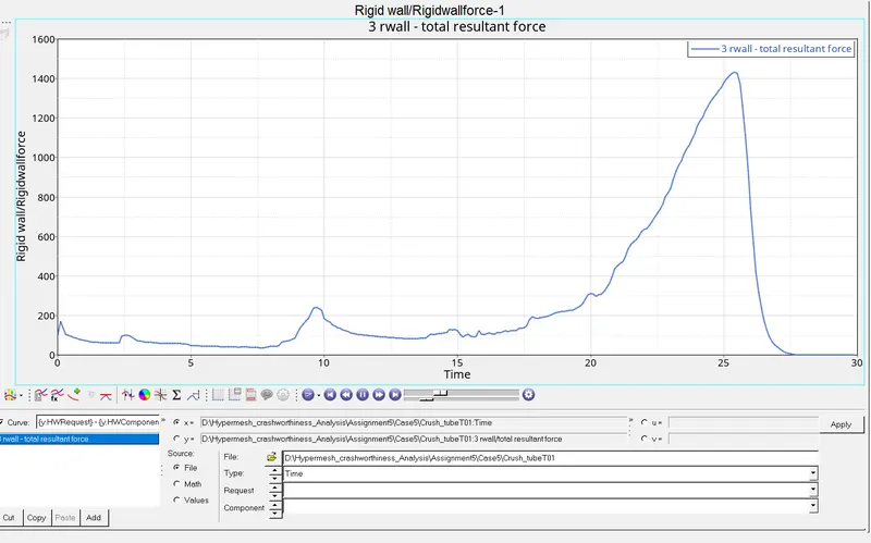
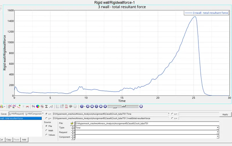
The Rigid wall force starts to increase at 20ms. Rigid wall force range between 0 to 200N after 20ms it increase upto 1400N at the end.
Iteration :2
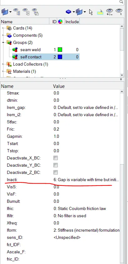
Change the Inacti=6 and run.
Inacti - 6 Gap is variable with time but inital gap is adjusted as (the node is slightly depenerated)
Fric - Friction value is taken as 0.2 we can take between 0 to 1.
Istif - Taking Istif 4 as master is rigid wall so it has mininmum stiffness.
Gapmin - Gap min is set as 1
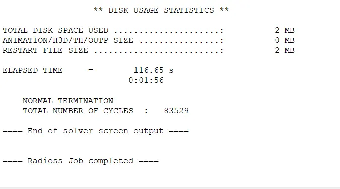
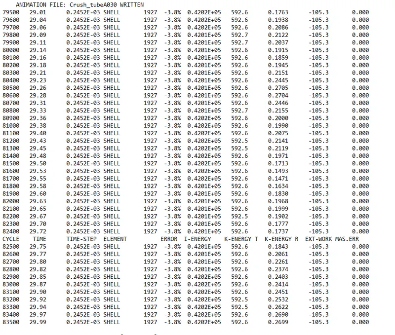
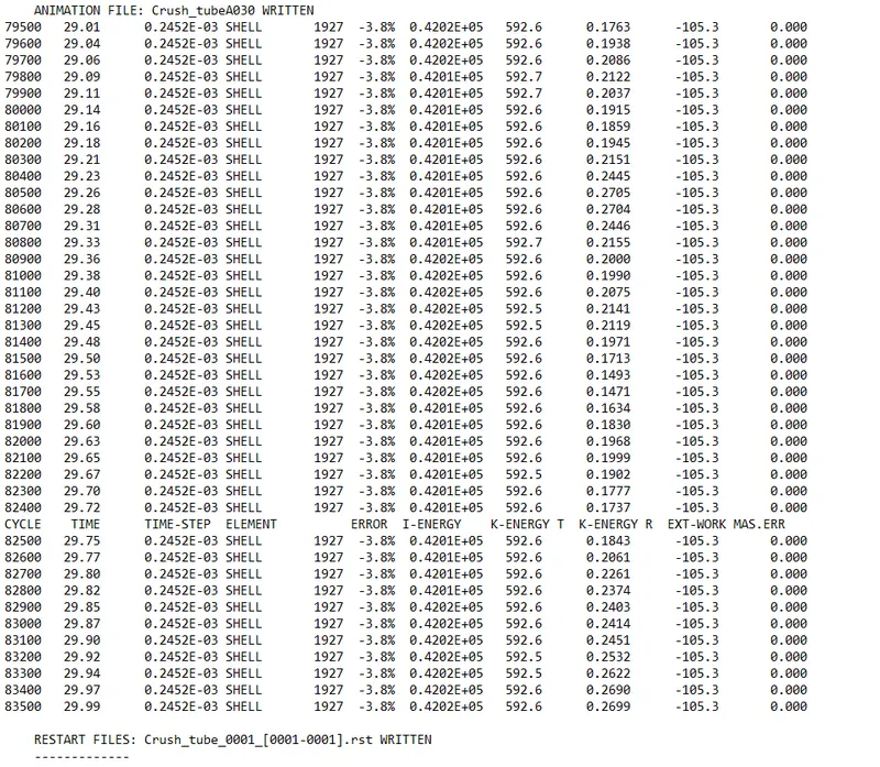
The energy error is 3.8% which is acceptable and mass error is 0
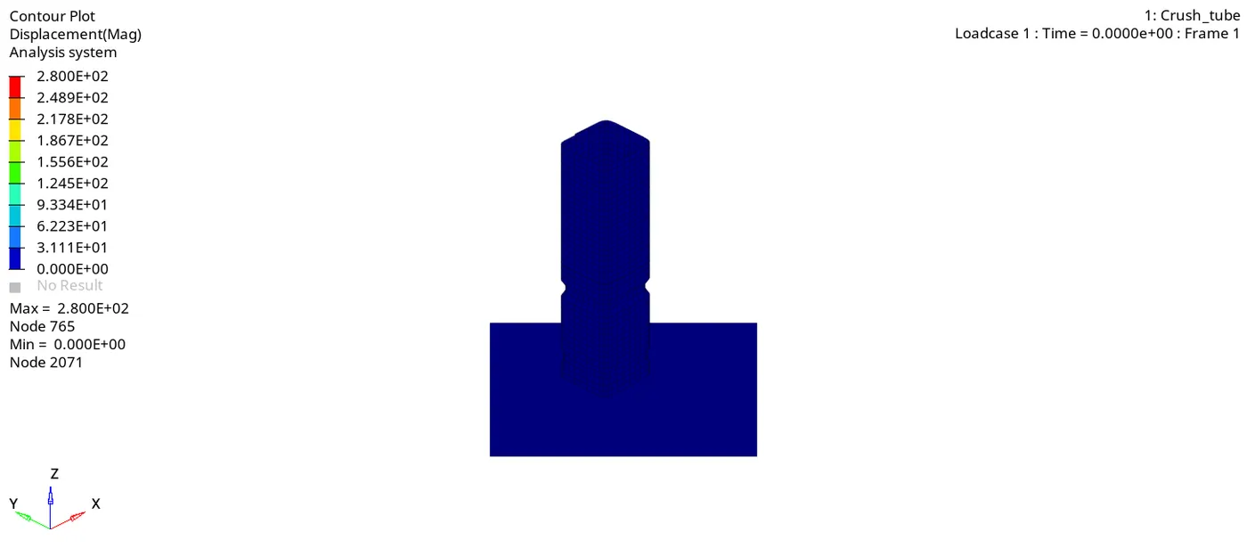
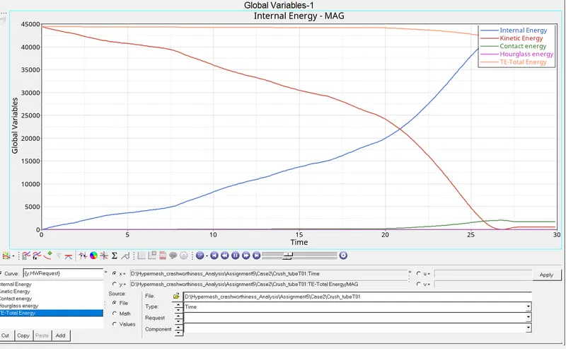
The internal energy is gradually increasing and kinetic energy is decreasing. Contact energy remains zero until 15ms and then increases slightly.Hourglass energy remains zero. Total energy is constant until 20ms and decreases slightly.
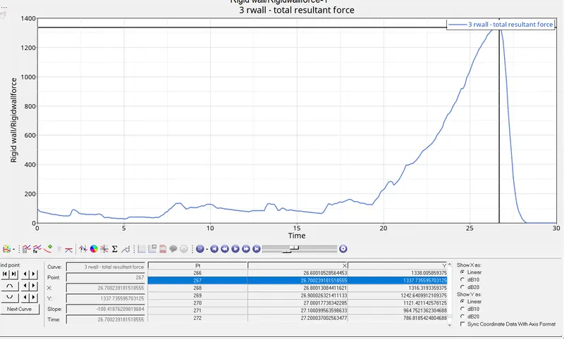
The max rigid wall force 1337 at 26.7ms.The crush tube contact the rigid wall at the end therefore the maximum force is acting at the end of simulation.
Iteration :3
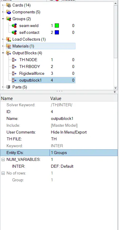
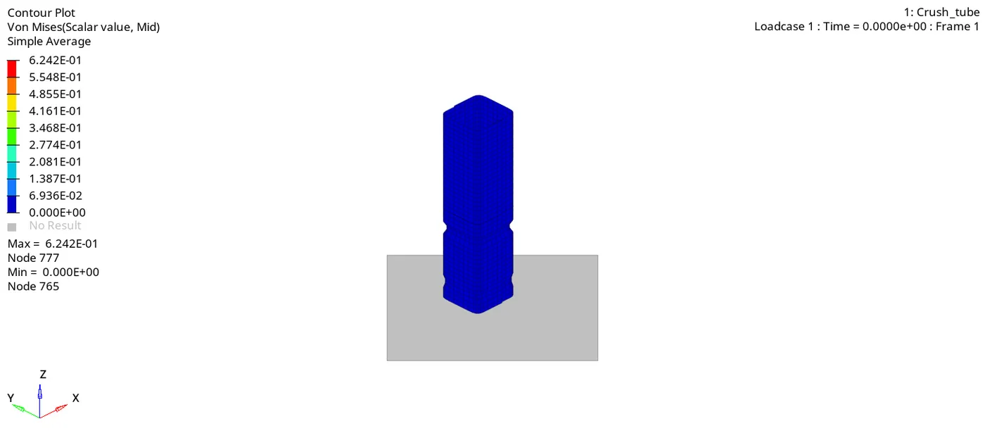
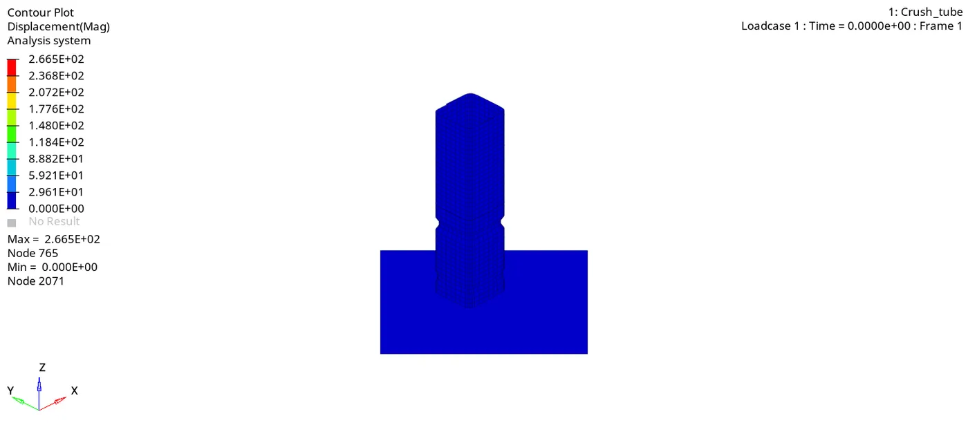
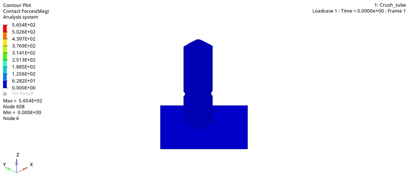
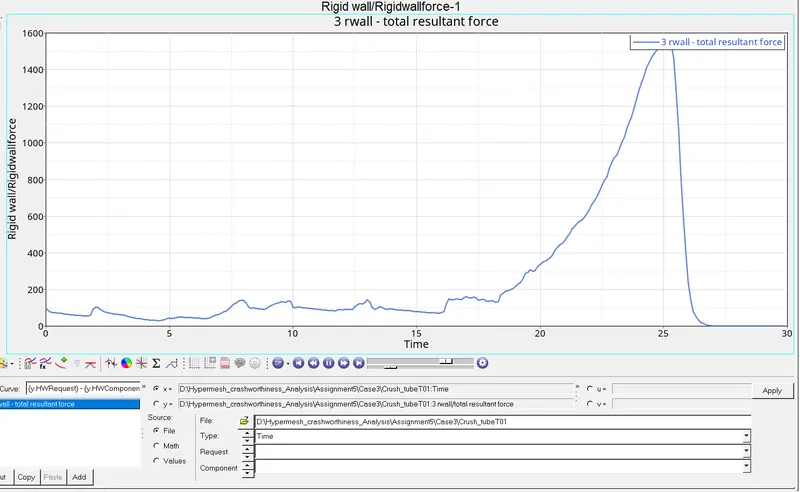
Create the type 11 contact and run.
/INTER/TYPE11
This interface simulates between edge to edge or line.A line can be a beam or truss element or a shell edge or spring elelment.
The interface properties are -
Impact occurs between a master and a slave line.
A slave line can impact on one or more master lines.
A line can belong to master or slave side. This allows self impact.
This impact can be use in addition to /INTER/TYPE7 to solve the edge to edge limitation of interface TYPE7
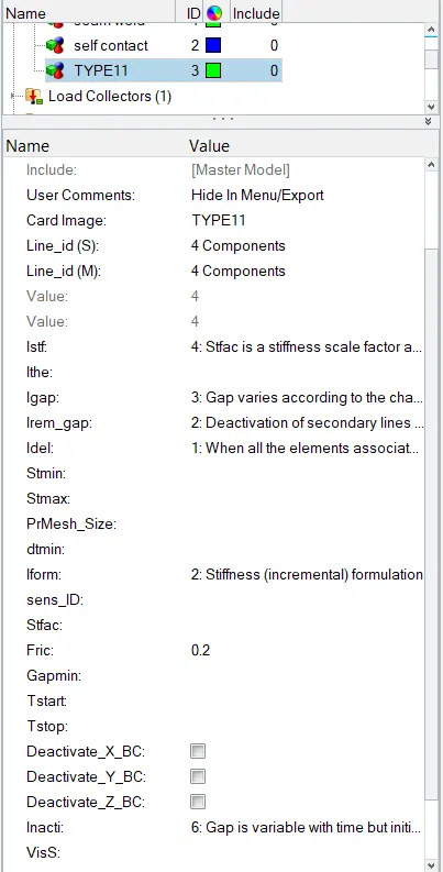
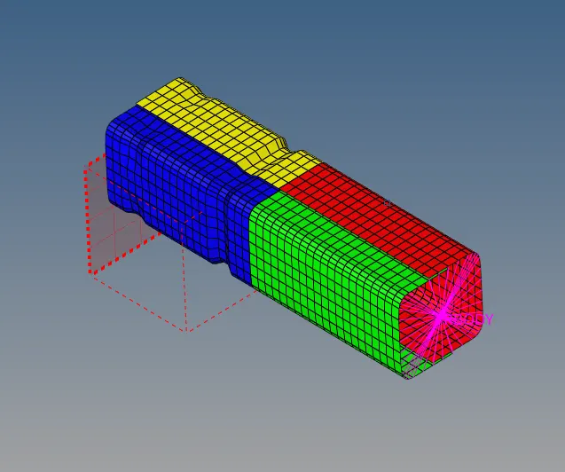
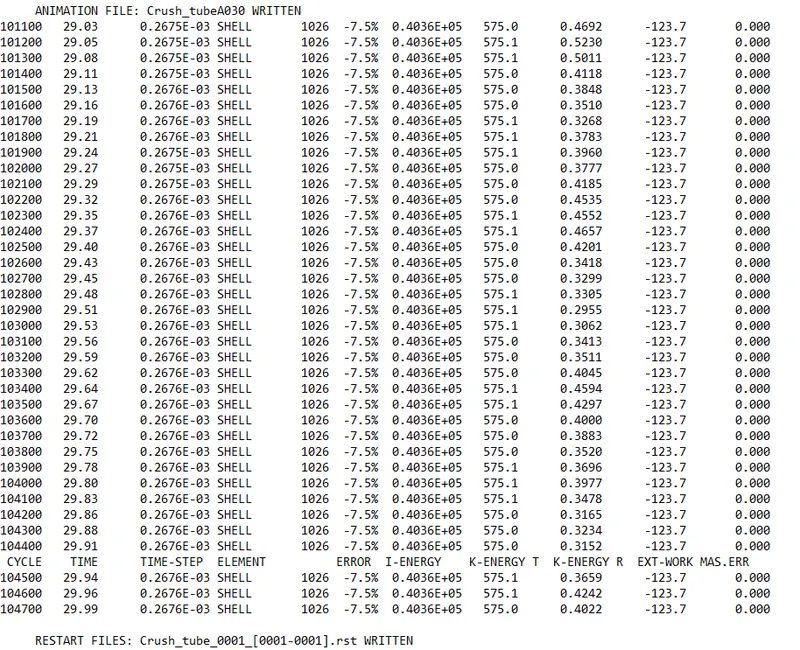
The Energy error is 7.5 and mass error is 0.
Iteration : 4
Remove both notches and remove boundary condition on rigid body node then run.
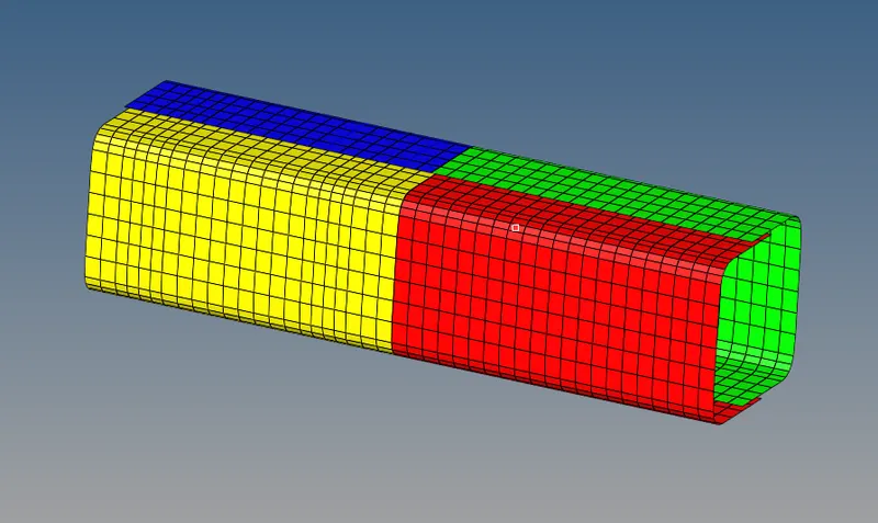
To rermove notches - Delete the element where the notches are and then create the new mesh by 2D -ruled surf - select the node list and mesh with keep surf option. Both nothes were removed and resmeshed the geometry.
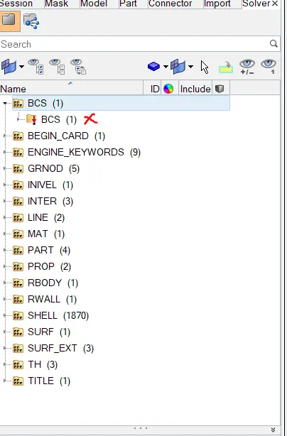
To delete the Boundary condition goto View - Browser - Hypermesh - Solver this will show the boundary condition.
Delete the BCS i.e Boundary conditions.
Now Run the analysis. Goto - Analysis -Radioss.
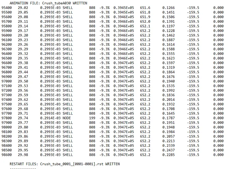
The energy error is observed as 9.3% out of 15% which is acceptable and can be proceed to analysis.
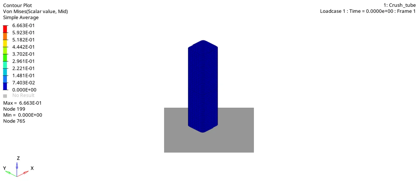
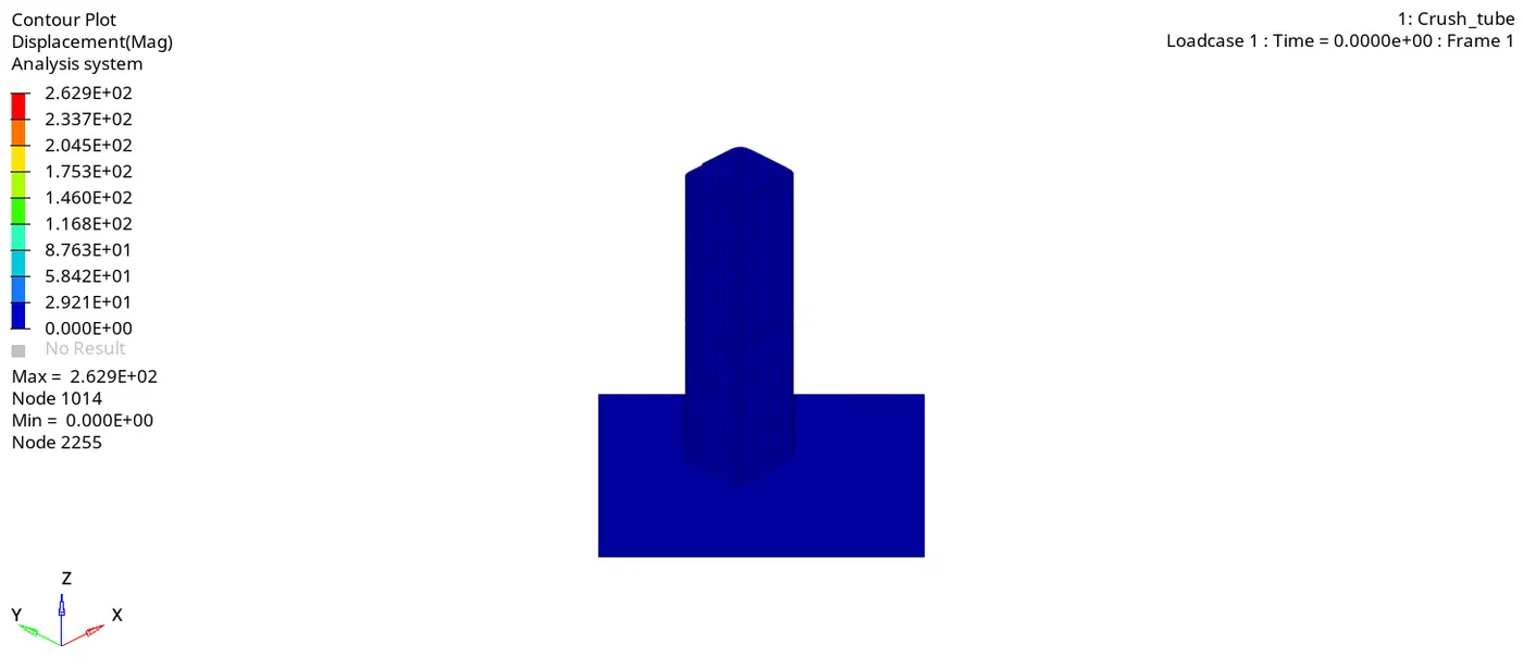
Due to removal of notches the deformation is occuring at the end.
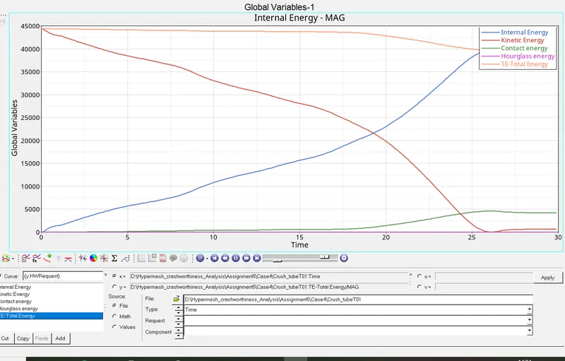
We can observe that the conversion of kinetic energy is depenedent on notches in the tube.due to this it will take time to convert into internal energy. But if notches are removed it will directly convert internal energy.
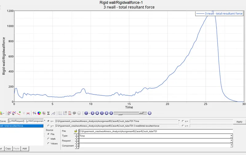
The Rigid wall force is nearly 1200N in about 26 ms. We have observed that maximum rigid wall force due to change in TYPE11.The force is decreased due to notches not present in the model.
Iteration : 5
Create a new notch in the middle ,select the whole section and run.
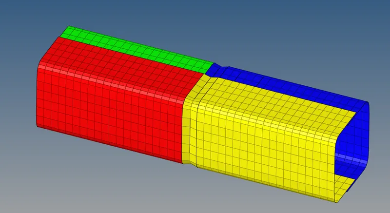
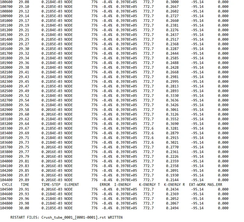
The energy Error is 8.4% and it satisfied with the ideal condition of 15% Mass error is 0%
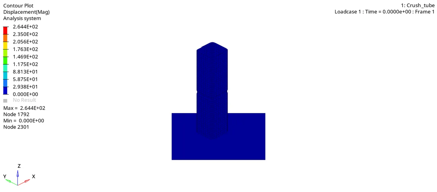
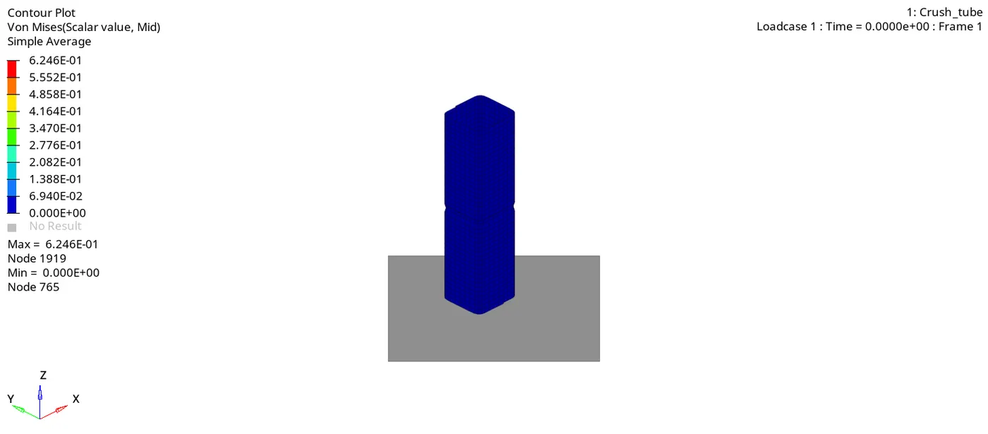
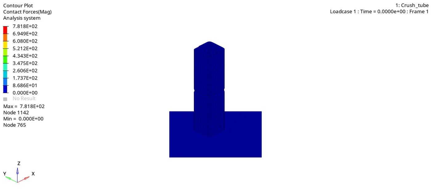
The maximum rigid wall force is observed just above 1400N at 26ms.
The kinetic energy is converted into internal energy just before 20ms.
Iteration : 6
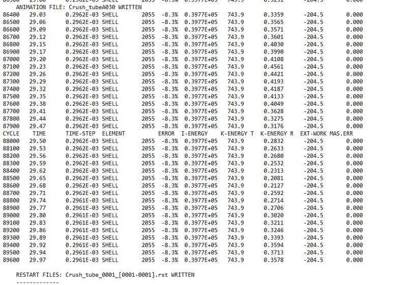
Create a new notch with nodes only from opposing 2 faces and run.
Notch has been created by using translate node.
Goto Tools - translate - select the node to translate - provide magnitude and direction move.
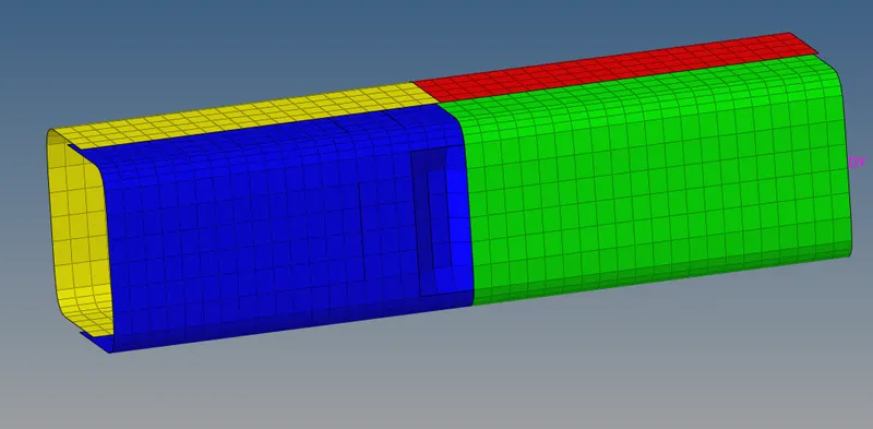
Now Run the Analysis.
Results :
Comparison between the all cases are given below - Energy error, Mass Error, Rigiwall force.
| No. | Details | Energy error | Mass Error | Rigid wall force |
| Iteration1 | Running the model as given | 3.8% | 0 | 1340 |
| Iteration2 | Change Inacti - 6 | 3.8% | 0 | 1337 |
| Iteration3 | TYPE 11 Interface | 7.5% | 0 | 1510 |
| Iteration4 | Removing Notches & BCS | 9.3% | 0 | 1200 |
| Iteration5 | Creating a Notch in center | 8.4% | 0 | 1410 |
| Iteration6 | Creating notch on opposite sides | 8.3% | 0 | 1440 |