RADIOSS Interfaces & Study of Effect of Notches
Objective: 1. Meshing of bumper assembly with six mm element size.
2. Radioss interfaces (type 7 and type 11) and study the effect of notches with a crash tube example.
Procedure:
Meshing of bumper assembly:
1. Import the bumper assembly into hypermesh.
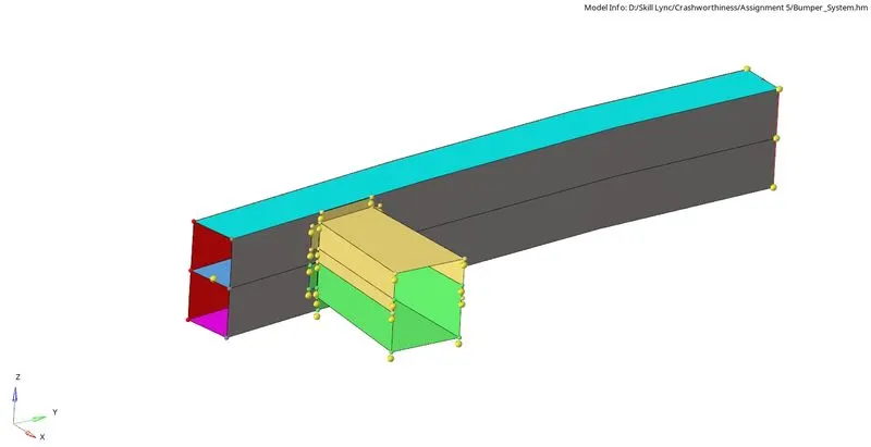
Fig 1: Bumper assembly.
2. Remove the unnecessary nodes in the geometry, which might disturb the mesh flow. Navigate to the temp nodes option in the geometry tab and clear all the nodes.

Fig 2: Options for adding or removing nodes.
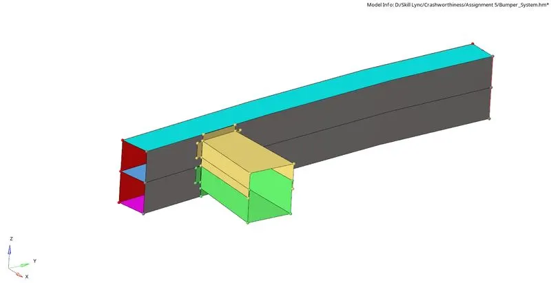
Fig 3: Unwanted nodes are removed from the geometry.
3. In the automesh option in the 2D tab, enter an element size of six units, choose all the surfaces, and hit mesh.

Fig 4: 2D meshing options.
4. Few 1D connectors are created between the crash beam and the bumper.

Fig 5: Options for creating 1D elements.

Fig 6: 1D elements are created in between the crash beam and the bumper.
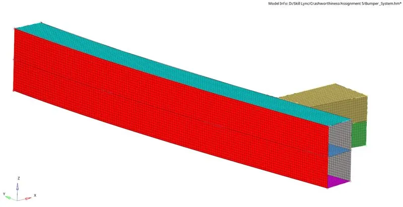
Fig 7: 2D elements generated on the bumper assembly.
Interfaces Study:
- Import the given 0000.rad file into hypermesh.
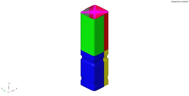
Fig 8: Geometry of crush tube.
Case 1: Type 7 Contact.
- The file is run as it is without any change in the values of contacts.
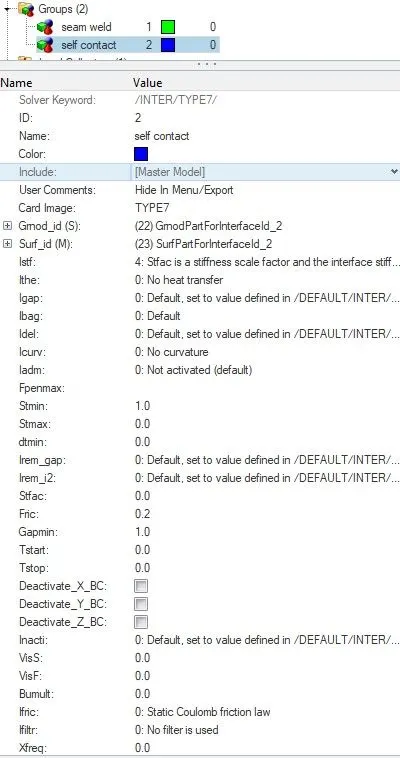
Fig 9: Interface card values.
- Now we can proceed to run our simulation. Navigate to the analysis tab and choose the radioss option.
- Input file option will be available to save the starter and engine file in the desired location.
- In the options bar, "-nt 6" is entered, which denotes parallel processing for the simulation.

Fig 10: Saving the file with an appropriate name.
- Once all the options are selected correctly, click on the radioss button to run the simulation.
- A separate window pops up and shows the calculation going on, and it might take up to few seconds to minutes based on the complexity of the solution.
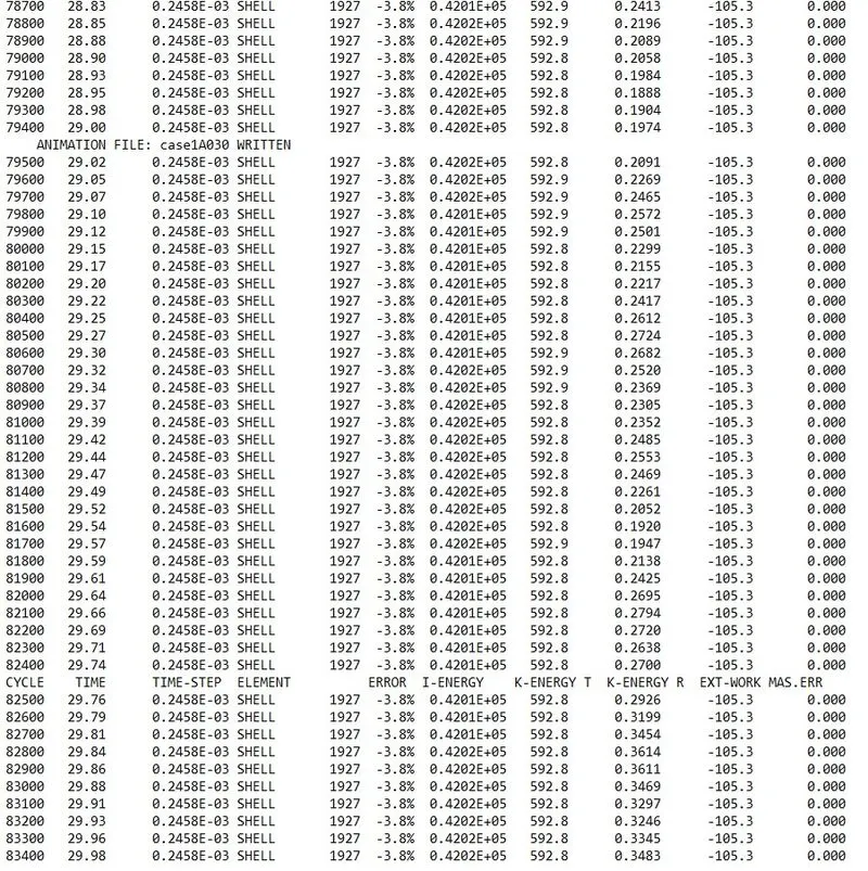
Fig 11: 0001.out files contains the solution information.
- We can check for the energy and mass error from the engine output file whether it lies within the permissible limit or not.
- The energy error starts from -0.0 to 3.8%, and the mass error is 0. Both are in the acceptable range, and we can proceed with the post-processing of our results.
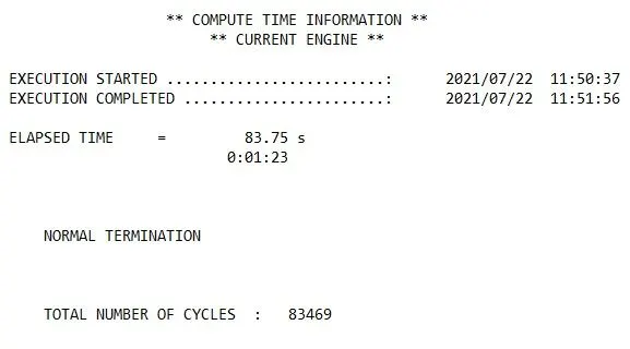
Fig 12: Compute time information.
- ELAPSED TIME = 83.75 s
- TOTAL NUMBER OF CYCLES: 83469
Results:
- For post-processing the results Hyperview and hypergraph are used.
- When hyperview is open, we need to load the model and results file of our simulation.

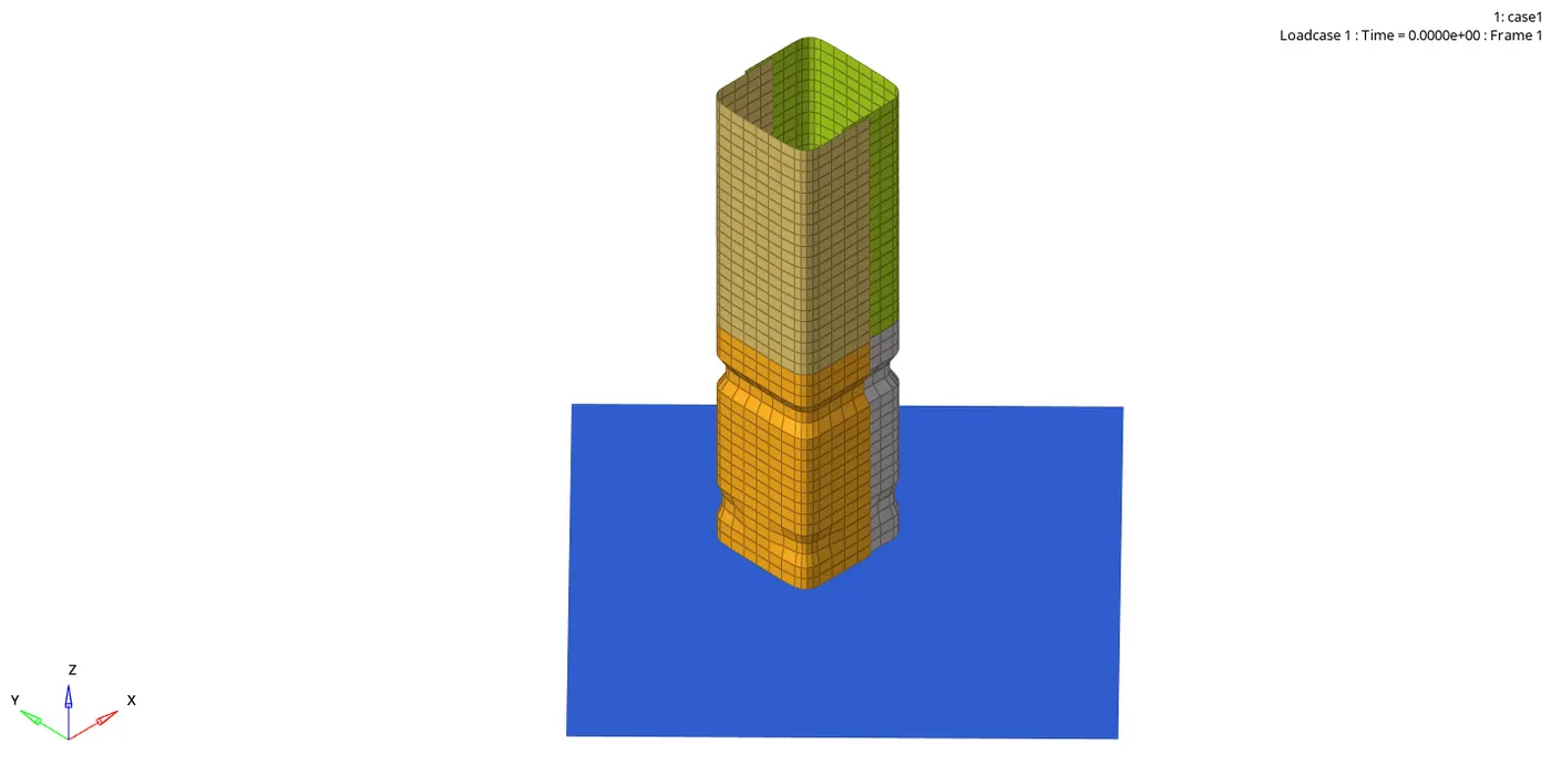
- The above animation represents the crush tube pressed onto the rigid wall.
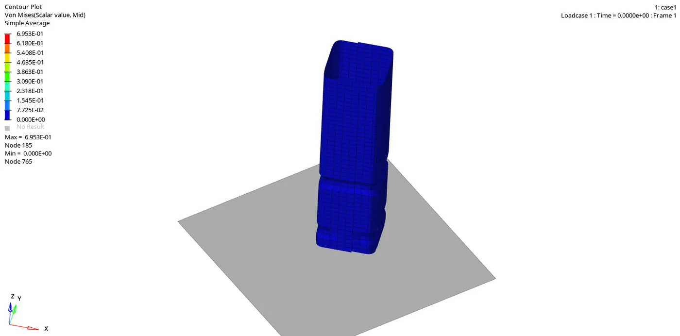
- The above animation represents the von mises stresses generated in the tube, and the maximum value is 6.953E-01.
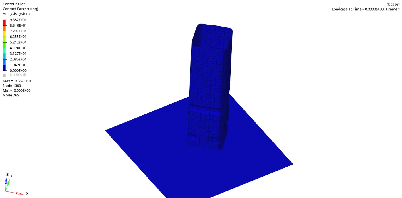
- The above animation represents the contact forces generated in the tube, and the maximum value is 9.382E+01.
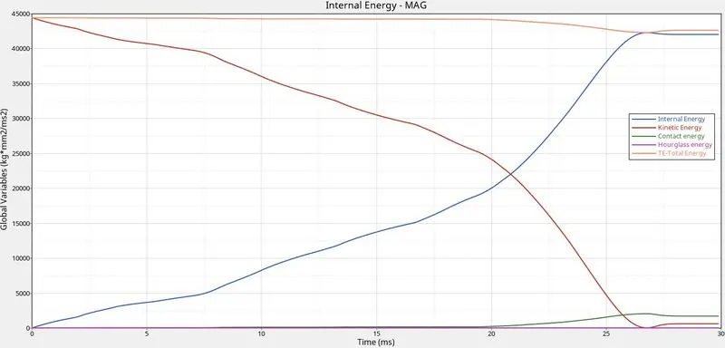
- The above plot shows the Total energy, Kinetic energy, Internal energy, hourglass energy, and contact energy.
- The total energy is the summation of an internal, kinetic, hourglass, and contact energy.
- Internal energy is the sum of kinetic and potential energy in a system.
- The hourglass energy is controlled because of the element formulation.
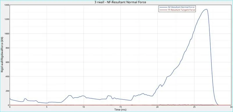
- The above plot shows the resultant normal force and resultant tangent force.
Case 2: Type 7 Contact with Inacti value set to 6.
- In this case, the Inacti value in the interface card is set to 6.
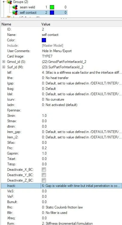
Fig 13: Interface card values.
- Rest all values are unaltered.
- Now we can proceed to run our simulation. Navigate to the analysis tab and choose the radioss option.
- Input file option will be available to save the starter and engine file in the desired location.
- In the options bar, "-nt 6" is entered, which denotes parallel processing for the simulation.
- Once all the options are selected correctly, click on the radioss button to run the simulation.
- A separate window pops up and shows the calculation going on, and it might take up to few seconds to minutes based on the complexity of the solution.
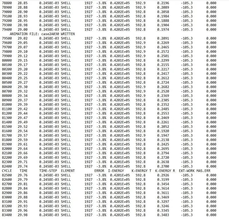
Fig 14: 0001.out files contains the solution information.
- We can check for the energy and mass error from the engine output file whether it lies within the permissible limit or not.
- The energy error starts from -0.0 to 3.8%, and the mass error is 0. Both are in the acceptable range, and we can proceed with the post-processing of our results.
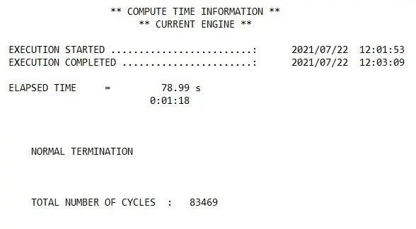
Fig 15: Compute time information.
- ELAPSED TIME = 78.99 s
- TOTAL NUMBER OF CYCLES: 83469
Results:
- For post-processing the results Hyperview and hypergraph are used.
- When hyperview is open, we need to load the model and results file of our simulation.
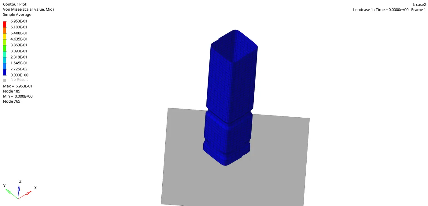
- The above animation represents the von mises stresses generated in the tube, and the maximum value is 6.953E-01.
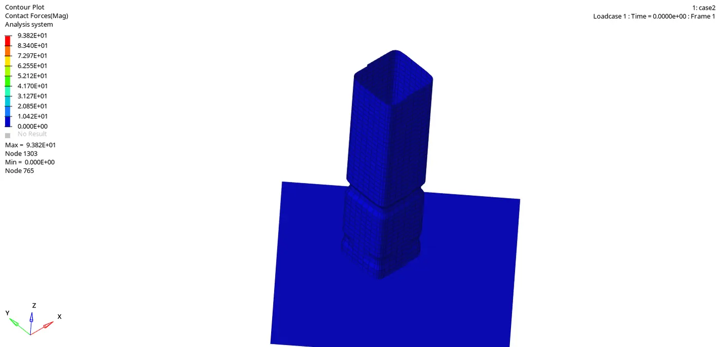
- The above animation represents the contact forces generated in the tube, and the maximum value is 9.382E+01.
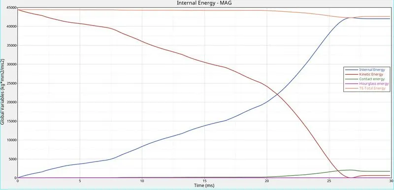
- The above plot shows the Total energy, Kinetic energy, Internal energy, hourglass energy, and contact energy.
- The total energy is the summation of an internal, kinetic, hourglass, and contact energy.
- Internal energy is the sum of kinetic and potential energy in a system.
- The hourglass energy is controlled because of the element formulation.
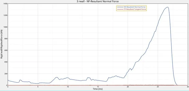
- The above plot shows the resultant normal force and resultant tangent force.
Case 3: Type 11 Contact.
- In this case, a new contact card is created with a type 11 card image.
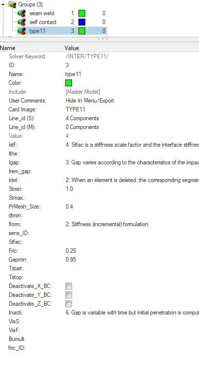
Fig 16: Interface card values.
- Rest all values are unaltered.
- Now we can proceed to run our simulation. Navigate to the analysis tab and choose the radioss option.
- Input file option will be available to save the starter and engine file in the desired location.
- In the options bar, "-nt 6" is entered, which denotes parallel processing for the simulation.
- Once all the options are selected correctly, click on the radioss button to run the simulation.
- A separate window pops up and shows the calculation going on, and it might take up to few seconds to minutes based on the complexity of the solution.
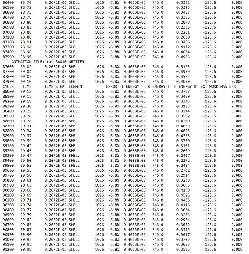
Fig 17: 0001.out files contains the solution information.
- We can check for the energy and mass error from the engine output file whether it lies within the permissible limit or not.
- The energy error starts from -0.0 to -6.8%, and the mass error is 0. Both are in the acceptable range, and we can proceed with the post-processing of our results.
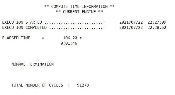
Fig 18: Compute time information.
- ELAPSED TIME = 106.20 s
- TOTAL NUMBER OF CYCLES: 91278
Results:
- For post-processing the results Hyperview and hypergraph are used.
- When hyperview is open, we need to load the model and results file of our simulation.
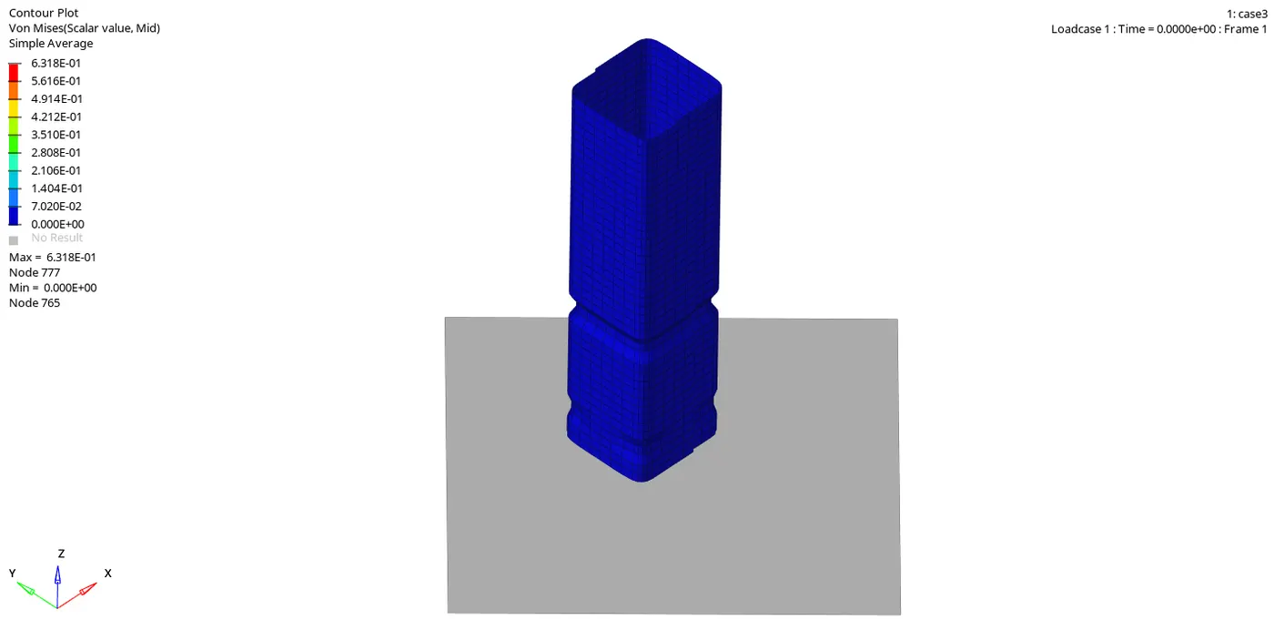
- The above animation represents the von mises stresses generated in the tube, and the maximum value is 6.318E-01.
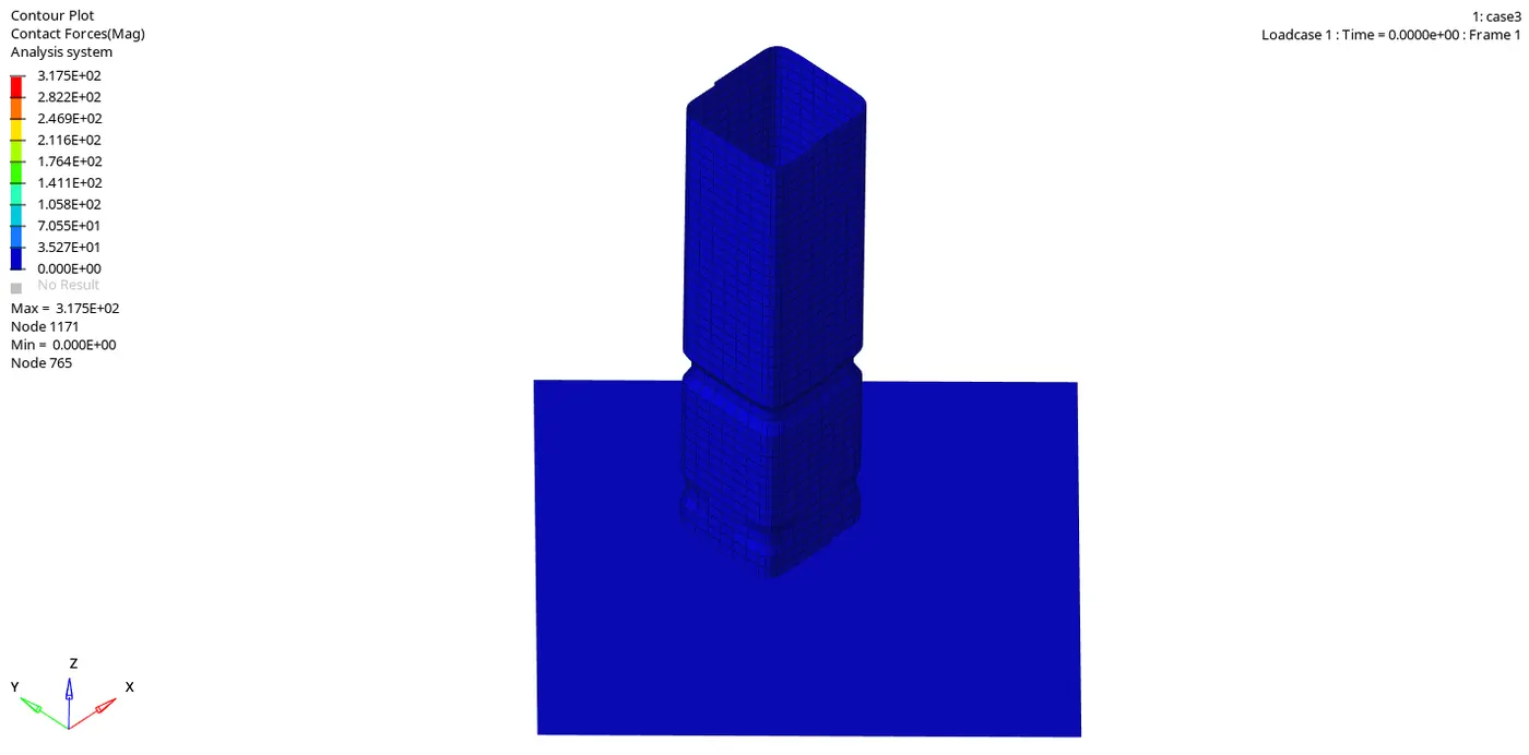
- The above animation illustrates the contact forces generated in the tube, and the maximum value is 3.175E+02.
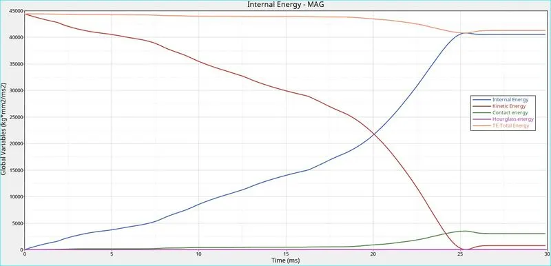
- The above plot shows the Total energy, Kinetic energy, Internal energy, hourglass energy, and contact energy.
- The total energy is the summation of an internal, kinetic, hourglass, and contact energy.
- Internal energy is the sum of kinetic and potential energy in a system.
- The hourglass energy is controlled because of the element formulation.
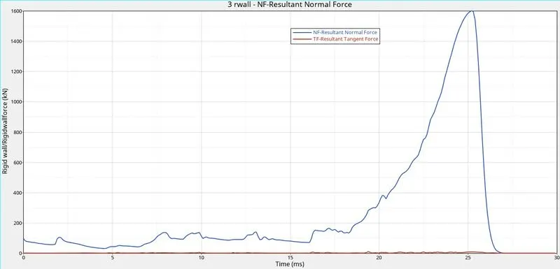
- The above plot shows the resultant normal force and resultant tangent force.
Discussion of Results of Cases 1, 2, and 3.
| Case | Type of Interface | Simulation time (sec) | Number of cycles | Energy Error % | Stress (MPa) | Contact Forces (N) |
| 1 | Type 7 | 83.75 | 83469 | -3.8 | 6.953E-01 | 9.382E+01 |
| 2 | Type 7 | 78.99 | 83469 | -3.8 | 6.953E-01 | 9.382E+01 |
| 3 | Type 11 | 106.20 | 91278 | -6.8 | 6.318E-01 | 3.175E+02 |
- Interpreting from the table, there is no change in the values of cases 1 and 2. We can notice identical stress and contact forces values because there are no initial penetrations in the model. Even though the Inacti is set to 6, no difference is produced.
- The addition of type 11 interface, i.e., edge-to-edge contact, produced slightly different values than other cases. In case 3, the node to the surface and the edge-to-edge contacts are considered, so the simulation time and the number of cycles also increased quite a bit.
- Contact forces are higher in case 3 due to other interface detection.
Effect of Notches:
Case 1: No notches.
- The notches in the geometry are removed using the align node option in the node edit command in the geometry tab.

Fig 19: Options for aligning nodes.
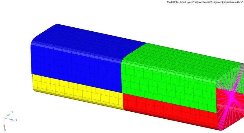
Fig 20: Notches are removed from the geometry.
- The boundary condition on the rigid body is removed. In the solver browser, under the BCS card, allow the translational and rotational motion for the rigid body.
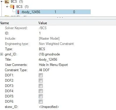
Fig 21: Boundary conditions are removed on the rigid body.
- Rest all values are unaltered.
- Now we can proceed to run our simulation. Navigate to the analysis tab and choose the radioss option.
- Input file option will be available to save the starter and engine file in the desired location.
- In the options bar, "-nt 6" is entered, which denotes parallel processing for the simulation.
- Once all the options are selected correctly, click on the radioss button to run the simulation.
- A separate window pops up and shows the calculation going on, and it might take up to few seconds to minutes based on the complexity of the solution.
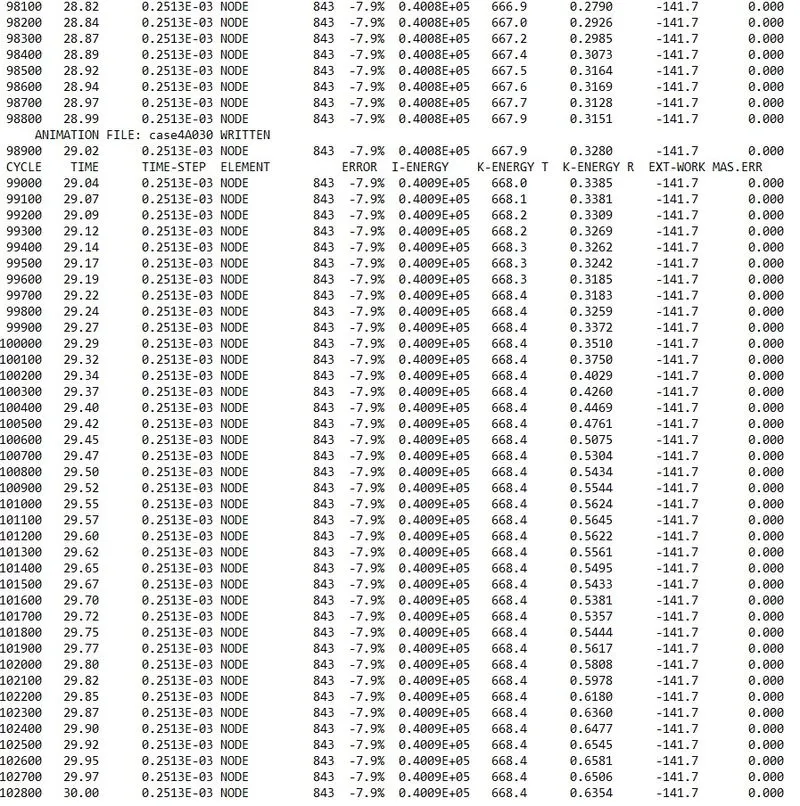
Fig 22: 0001.out files contains the solution information.
- We can check for the energy and mass error from the engine output file whether it lies within the permissible limit or not.
- The energy error starts from -0.0 to -7.9%, and the mass error is 0. Both are in the acceptable range, and we can proceed with the post-processing of our results.
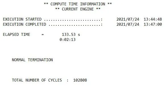
Fig 23: Compute time information.
- ELAPSED TIME = 133.53 s
- TOTAL NUMBER OF CYCLES: 102808
Results:
- For post-processing the results Hyperview and hypergraph are used.
- When hyperview is open, we need to load the model and results file of our simulation.
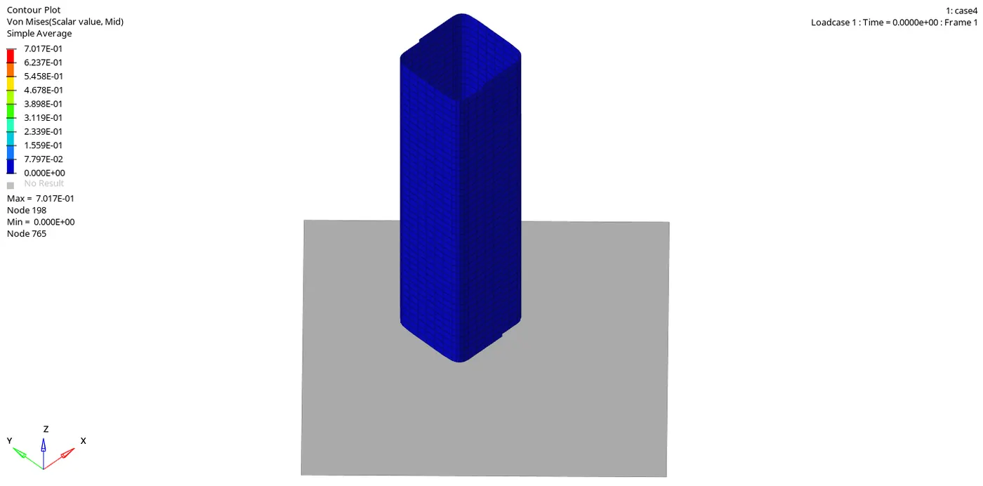
- The above animation represents the von mises stresses generated in the tube, and the maximum value is 7.017E-01.
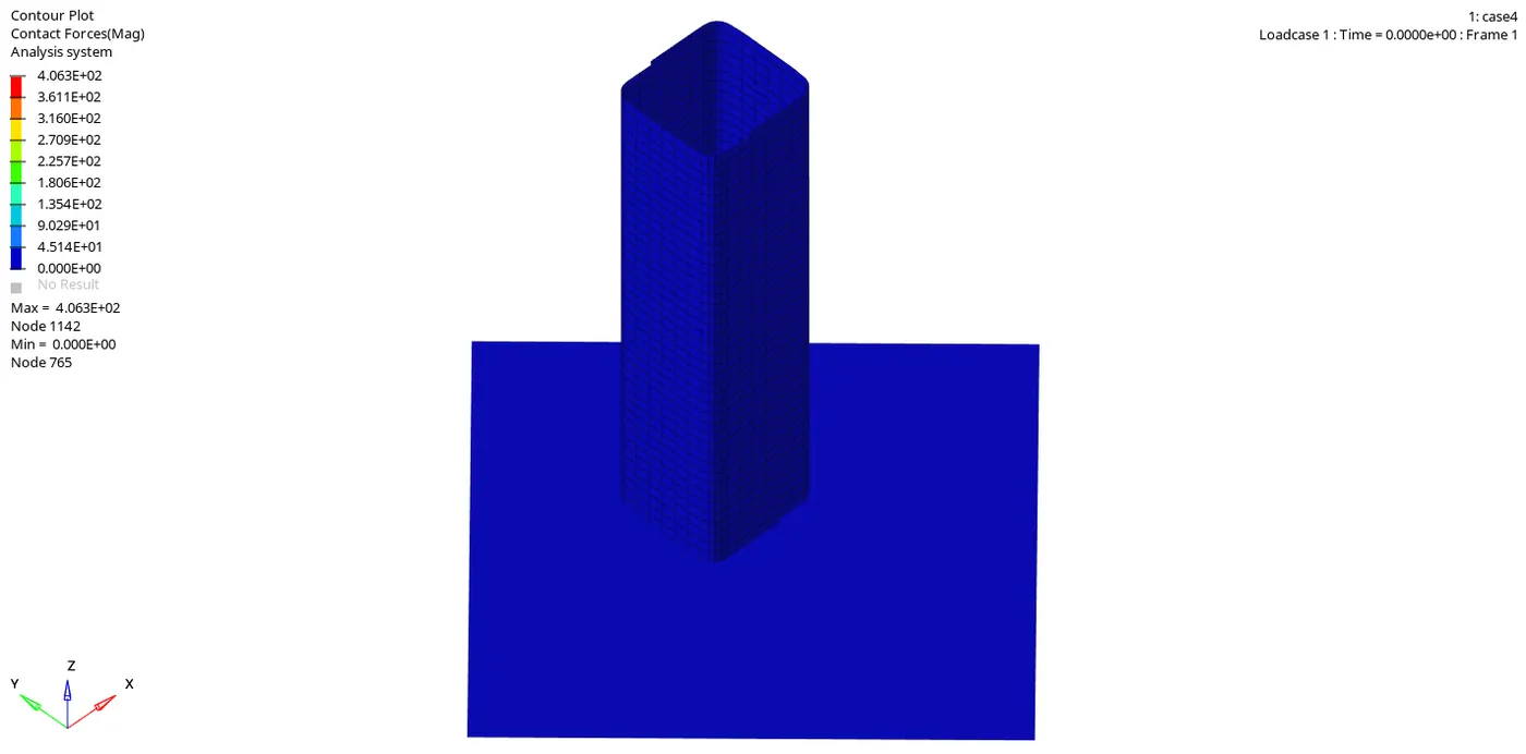
- The above animation illustrates the contact forces generated in the tube, and the maximum value is 4.063E+02.

- The above plot shows the Total energy, Kinetic energy, Internal energy, hourglass energy, and contact energy.
- The total energy is the summation of an internal, kinetic, hourglass, and contact energy.
- Internal energy is the sum of kinetic and potential energy in a system.
- The hourglass energy is controlled because of the element formulation.
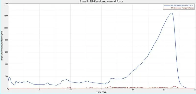
- The above plot shows the resultant normal force and resultant tangent force.
Case 2: Notch at the middle of the geometry.
- A notch is created at the mid of the geometry.
- Using the translate option, nodes can be translated in a particular direction with some magnitude value.

Fig 24: Node translation options.
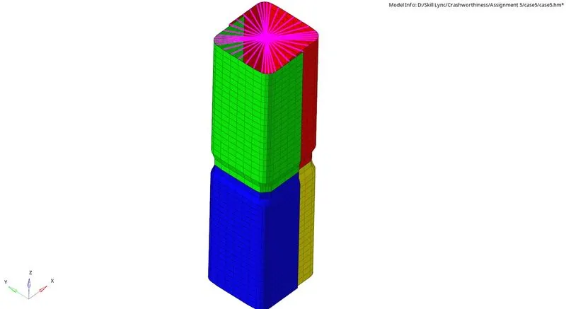
Fig 25: Notch is created at the middle of the geometry.
- Rest all values are unaltered.
- Now we can proceed to run our simulation. Navigate to the analysis tab and choose the radioss option.
- Input file option will be available to save the starter and engine file in the desired location.
- In the options bar, "-nt 6" is entered, which denotes parallel processing for the simulation.
- Once all the options are selected correctly, click on the radioss button to run the simulation.
- A separate window pops up and shows the calculation going on, and it might take up to few seconds to minutes based on the complexity of the solution.
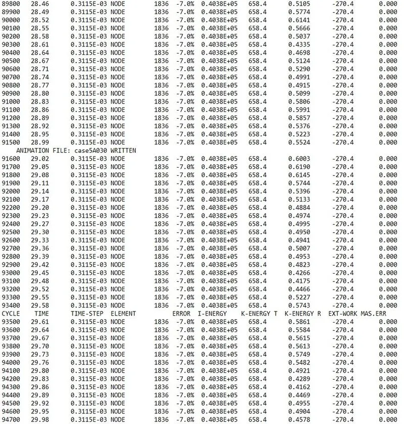
Fig 26: 0001.out files contains the solution information.
- We can check for the energy and mass error from the engine output file whether it lies within the permissible limit or not.
- The energy error starts from 0.0 to -7.0%, and the mass error is 0. Both are in the acceptable range, and we can proceed with the post-processing of our results.
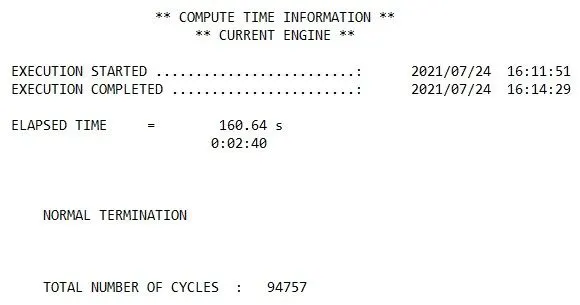
Fig 27: Compute time information.
- ELAPSED TIME = 160.64 s
- TOTAL NUMBER OF CYCLES: 94757
Results:
- For post-processing the results Hyperview and hypergraph are used.
- When hyperview is open, we need to load the model and results file of our simulation.
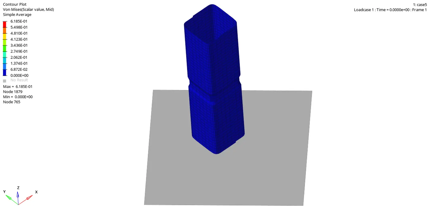
- The above animation represents the von mises stresses generated in the tube, and the maximum value is 6.185E-01.
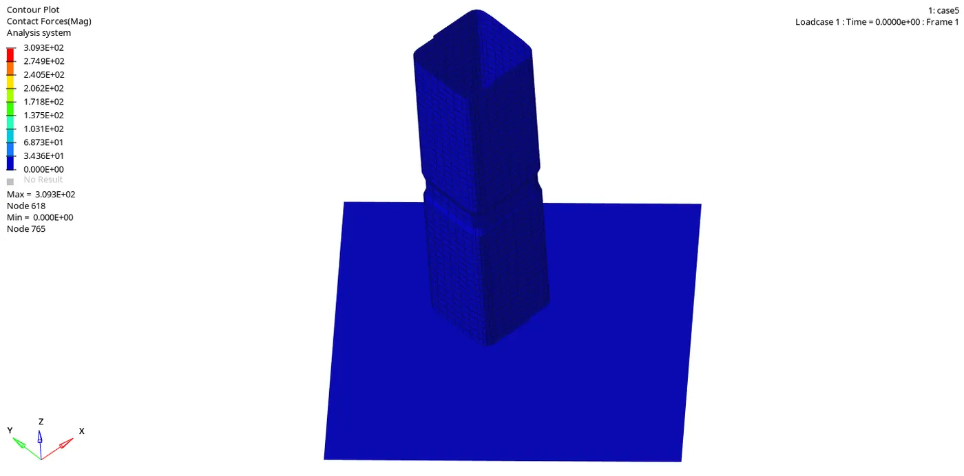
- The above animation illustrates the contact forces generated in the tube, and the maximum value is 3.093E+02.
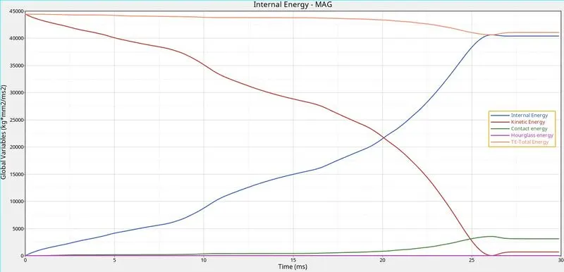
- The above plot shows the Total energy, Kinetic energy, Internal energy, hourglass energy, and contact energy.
- The total energy is the summation of an internal, kinetic, hourglass, and contact energy.
- Internal energy is the sum of kinetic and potential energy in a system.
- The hourglass energy is controlled because of the element formulation.
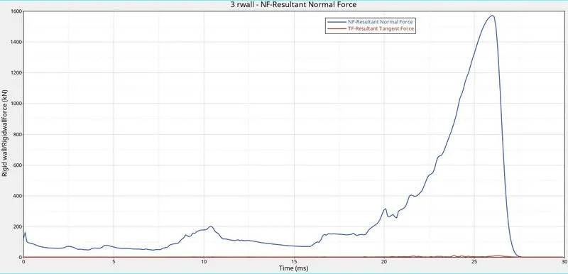
- The above plot shows the resultant normal force and resultant tangent force.
Case 3: Notch on the opposite faces of the geometry.
- Notches are made on the opposite faces of the geometry with the help of translate node options.
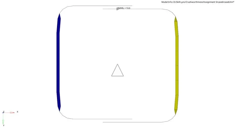
Fig 28: Notches on the opposite faces.
- Rest all values are unaltered.
- Now we can proceed to run our simulation. Navigate to the analysis tab and choose the radioss option.
- Input file option will be available to save the starter and engine file in the desired location.
- In the options bar, "-nt 6" is entered, which denotes parallel processing for the simulation.
- Once all the options are selected correctly, click on the radioss button to run the simulation.
- A separate window pops up and shows the calculation going on, and it might take up to few seconds to minutes based on the complexity of the solution.
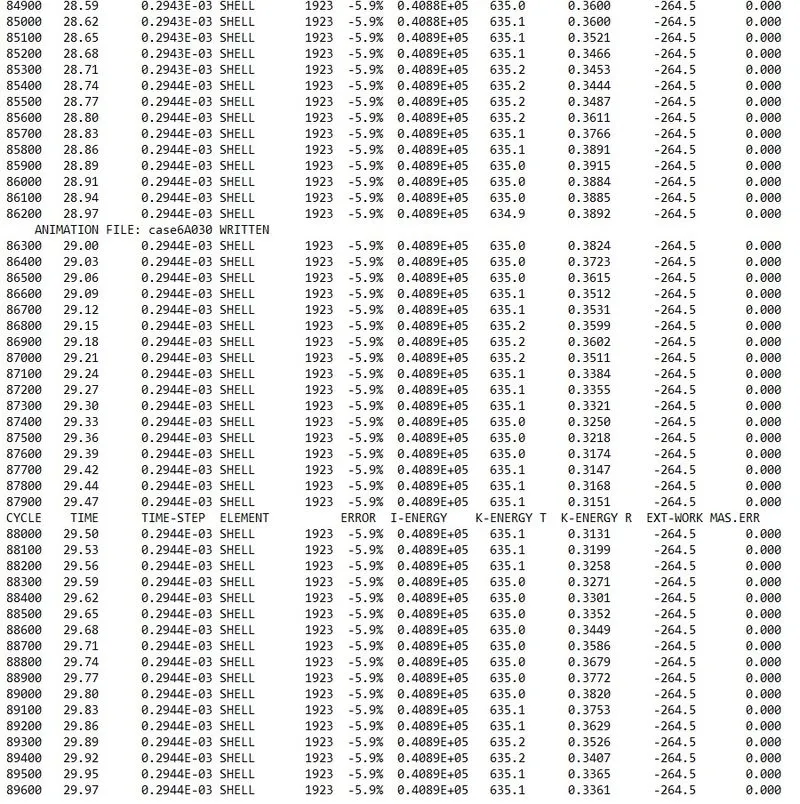
Fig 29: 0001.out files contains the solution information.
- We can check for the energy and mass error from the engine output file whether it lies within the permissible limit or not.
- The energy error starts from -0.0 to -5.9%, and the mass error is 0. Both are in the acceptable range, and we can proceed with the post-processing of our results.
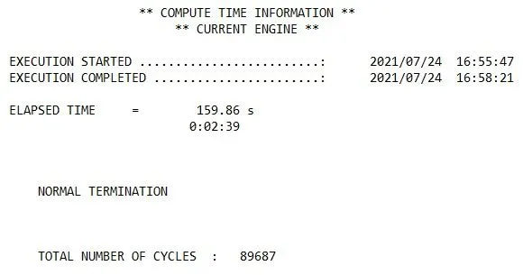
Fig 30: Compute time information.
- ELAPSED TIME = 159.86 s
- TOTAL NUMBER OF CYCLES: 89687
Results:
- For post-processing the results Hyperview and hypergraph are used.
- When hyperview is open, we need to load the model and results file of our simulation.
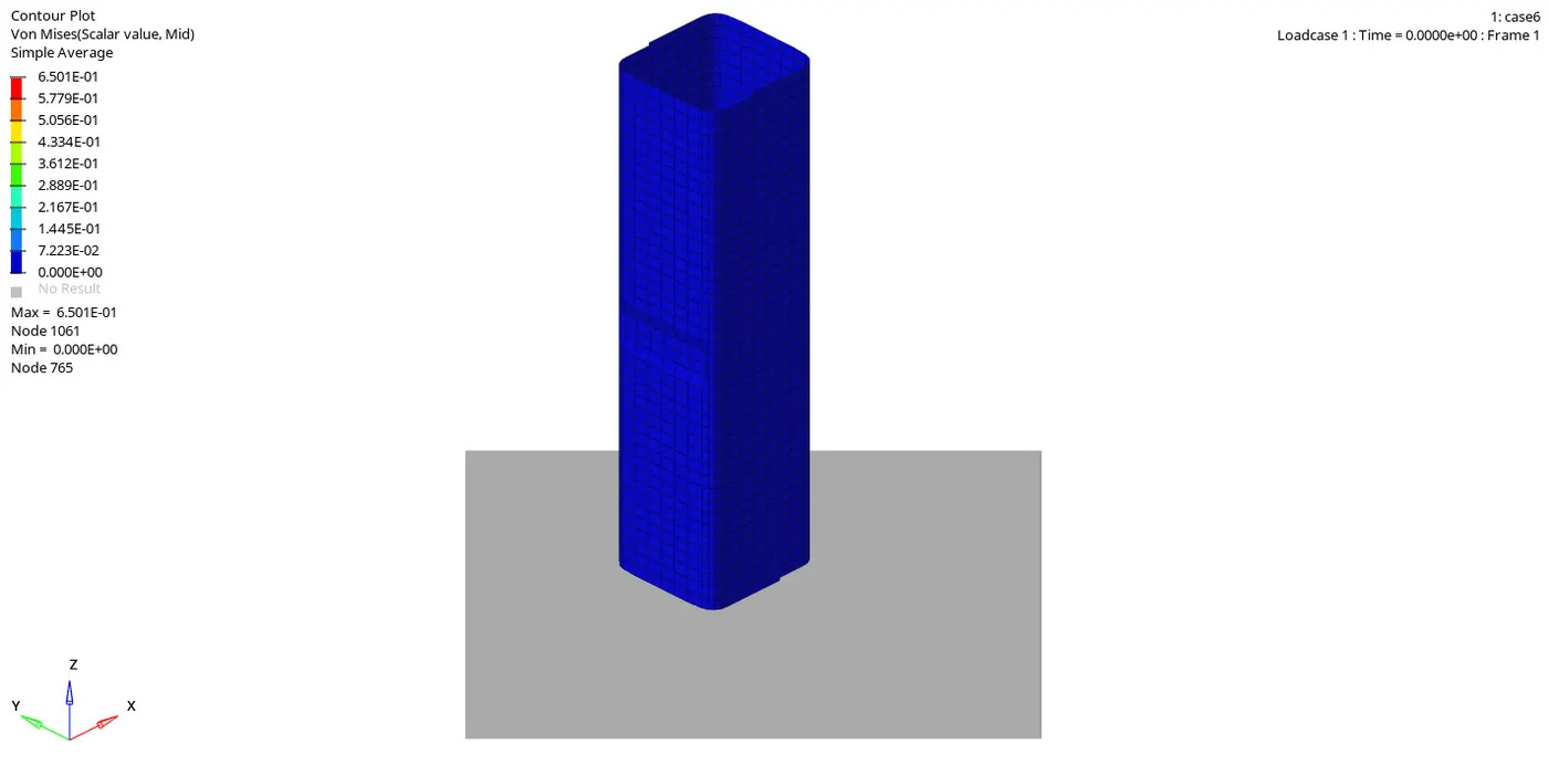
- The above animation represents the von mises stresses generated in the tube, and the maximum value is 6.501E-01.
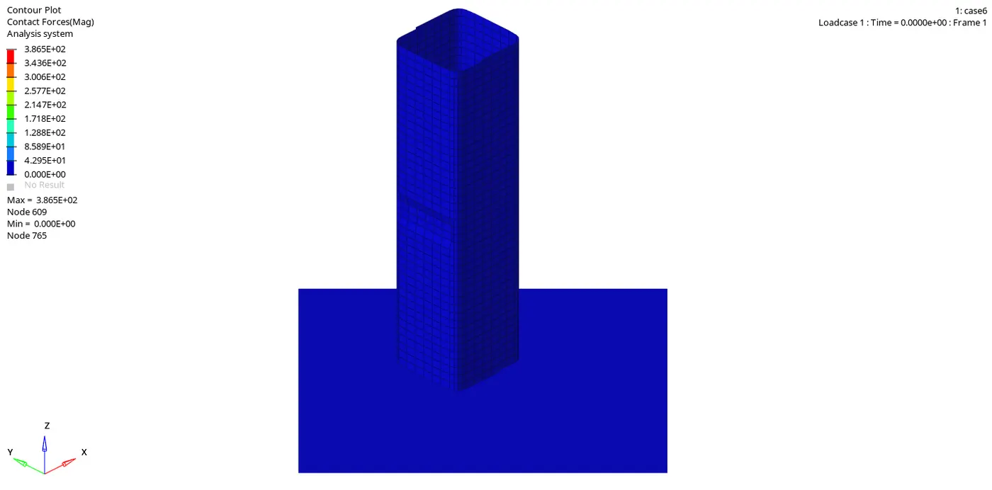
- The above animation illustrates the contact forces generated in the tube, and the maximum value is 6.865E+02.
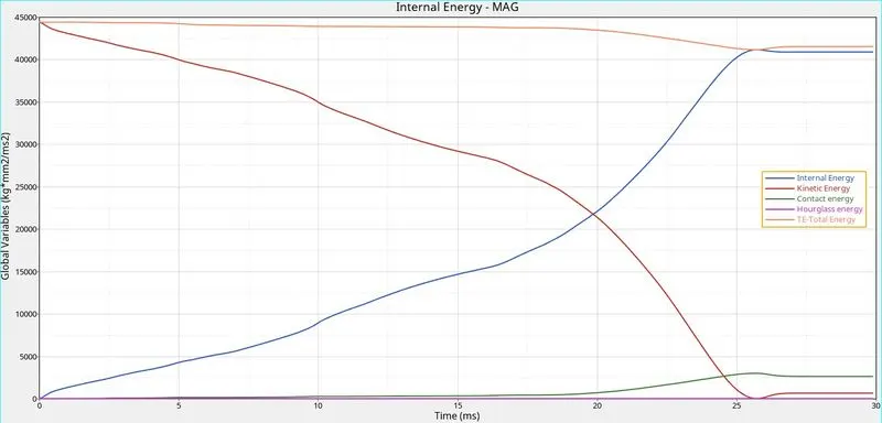
- The above plot shows the Total energy, Kinetic energy, Internal energy, hourglass energy, and contact energy.
- The total energy is the summation of an internal, kinetic, hourglass, and contact energy.
- Internal energy is the sum of kinetic and potential energy in a system.
- The hourglass energy is controlled because of the element formulation.
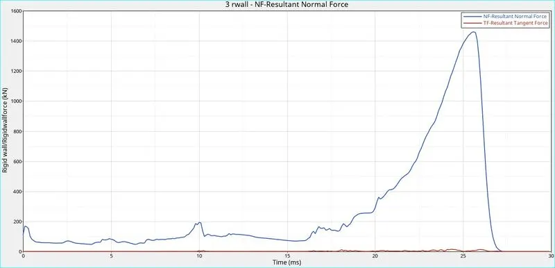
- The above plot shows the resultant normal force and resultant tangent force.
Discussion of Results of Cases 1, 2, and 3.
| Case | Notch location | Simulation time (sec) | Number of Cycles | Energy Error% | Stress (MPa) | Contact Forces (N) |
| 1 | No Notches | 133.53 | 102808 | -7.9 | 7.017E-01 | 4.063E+02 |
| 2 | Middle | 160.64 | 94757 | -7.0 | 6.185E-01 | 3.093E+02 |
| 3 | Opposite faces only | 159.86 | 89687 | -5.9 | 6.501E-01 | 3.865E+02 |
- The presence of notches increases the solution time. Adversely the stresses produced in the model with notches are less than the model without notches.
- Notches are provided in the crash beam to give the location of crushing. These are very much needed because, in a crash scenario, the crash beam must absorb the energy and at the same time crush so that less shockwave is sent to the occupants.
- In case 1, where there're no notches in the beam, we can observe higher stresses which are good, but again, the internal energy absorbed is slightly lower than in the other two cases.
- Here case 3 is an ideal choice because it has adequate stiffness and has higher internal energy compared to other cases.
Conclusions: 1. Two types of interfaces, i.e., type 7 and type 11, are studies with a crash tube example.
2. Also, the effect of notches is studied with a crash tube example.