Assignment 5-RADIOSS Interfaces & Study of Effect of Notches Challenge
ASSIGNMENT 5 : RADIOSS INTERFACE AND STUDY OF EFFECT OF NOTCHES
AIM:
- To mesh the given bumper model with target element length 6
- To run the crash tube simulation for various cases.
PROCEDURE:
A] Meshing the bumper assembly model.
Importing the given model
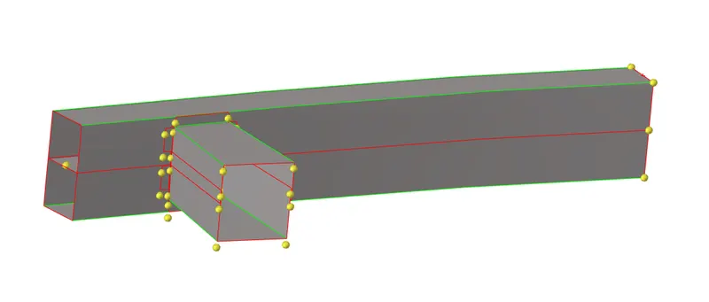
Switching the view to topo mode to see the free edges of the model assembly.
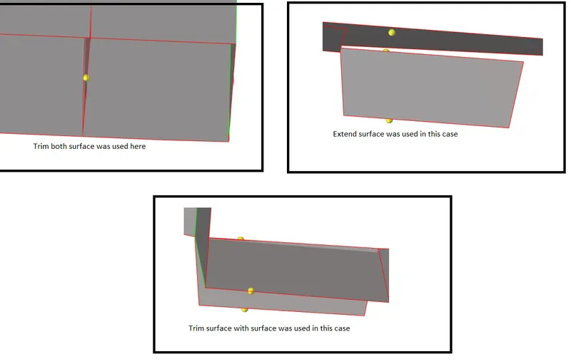
Trimming and extending surfaces for geometry cleanup.
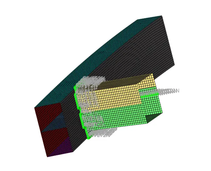
After performing geometry cleanup, we mesh the component. Automesh panel from the 2D section is used for performing the meshing operation. We select the target element length of 6 mm and do the meshing.
We then proceed to create connectors between crash box and bumper beams.
Connectors can be created by using connectors panel from either 1D or 2D section.
Below is the final product.
2] Radioss Interface and Study of effect of notches
CASE 1
Importing the given crush_tube_0000.rad file.
Running the analysis as it is without changing any parameter.
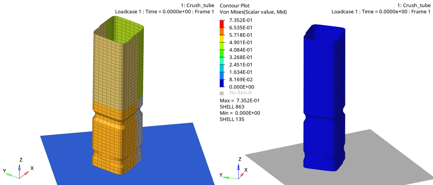
From the simulation shown above we see that the elements below the notch start failing first.
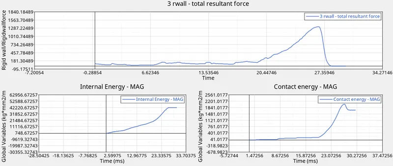
From the graphs we see that rigid wall forces spike when the tube is crushed completely.
Internal energy rises continuously until the tube gets crushed completely.
CASE 2
We import the given crush_tube_0000.rad file.
Changing the value of inacti=6 in type 7 contact group. Inact is used to auto correct the initial penetrations happening due to the defined contact.
Running the analysis and saving it as case2_0000.rad
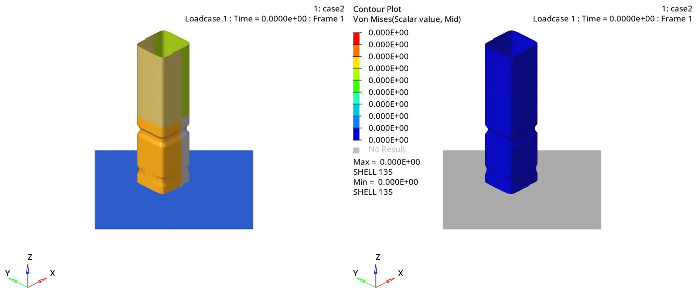
From the above simulation we see that the crushing pattern is similar to the case 1.
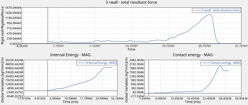
By observing the graphs, we see that the graphs are similar to case 1 graphs. This means that there was no initial penetration occurring.
CASE 3
We import the case2_0000.rad file.
We now add type 11 contact with the recommended parameters. Type 11 simulates edge to edge contact. This helps in analysing the problem in which the edges interfere with surface without the nodes touching the surface.
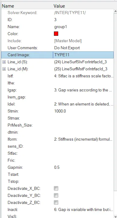
Running the analysis and saving it as case3_0000.rad.
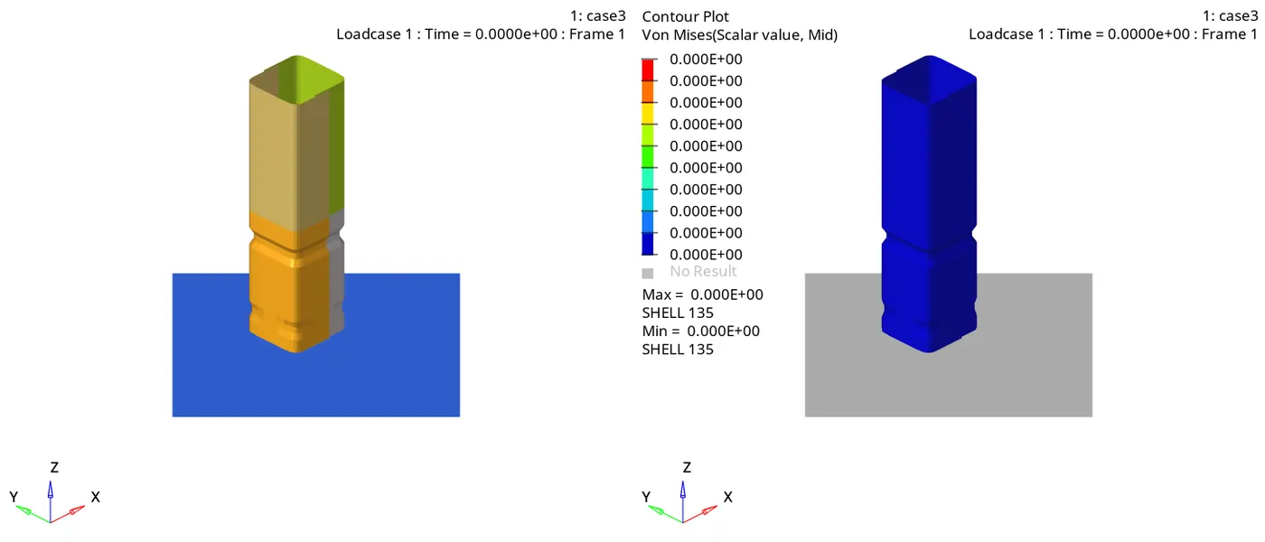
From the above gif we observe that the crushing pattern is similar to the previous cases.
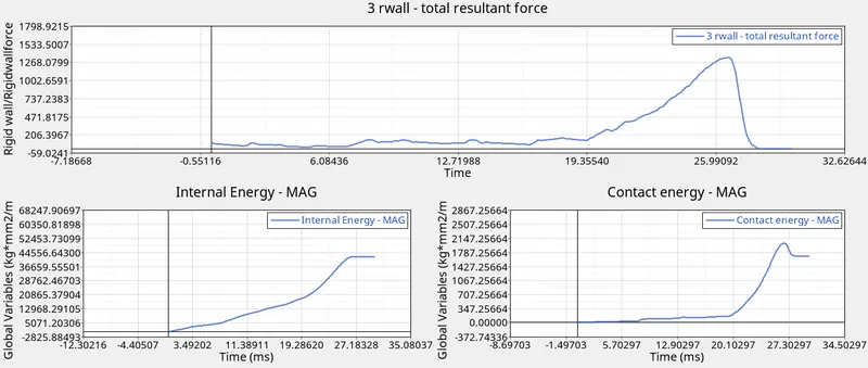
Also graphs, shown above are also similar to the previous cases. So the type 11 contact isn’t helpful in this simulation as there is no edge to surface contact.
CASE 4
In this case we import the case3_0000.rad.
We remove the notches which are present in the model using node edit panel.

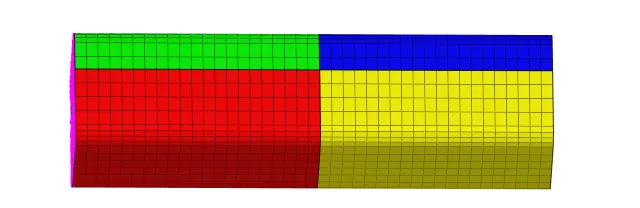
Also delete the boundary conditions.
Now running the simulation and saving it as case4_0000.rad.
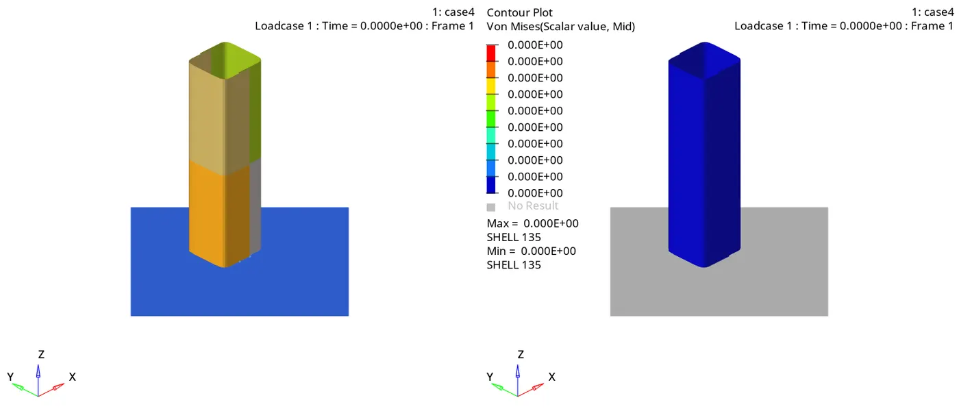
From the above simulation we see that the crushing starts from the bottom layer. The crushing occurs from bottom to top section.
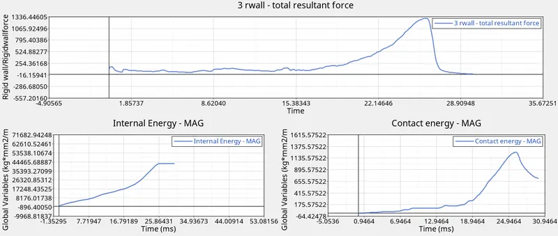
We see that rwall forces rise when the crushing starts and then drops down and stays constant for a while and then again starts rising until the whole tube gets crushed. The rwall forces are comparatively cases as in this case.
We also observe that towards the end of simulation there is a slight rise in contact which can suggest that after the contact takes place between all the layers, the middle layers and lower layers rebound.
CASE 5
We now import the case4_0000.rad file.
We create a notch exactly at the middle of the structure using translate panel. We translate the nodes by 2.5 mm.
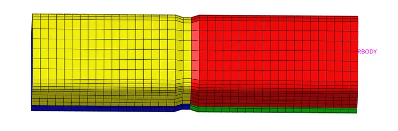
We save the file as case5_0000.rad and the run the simulation.
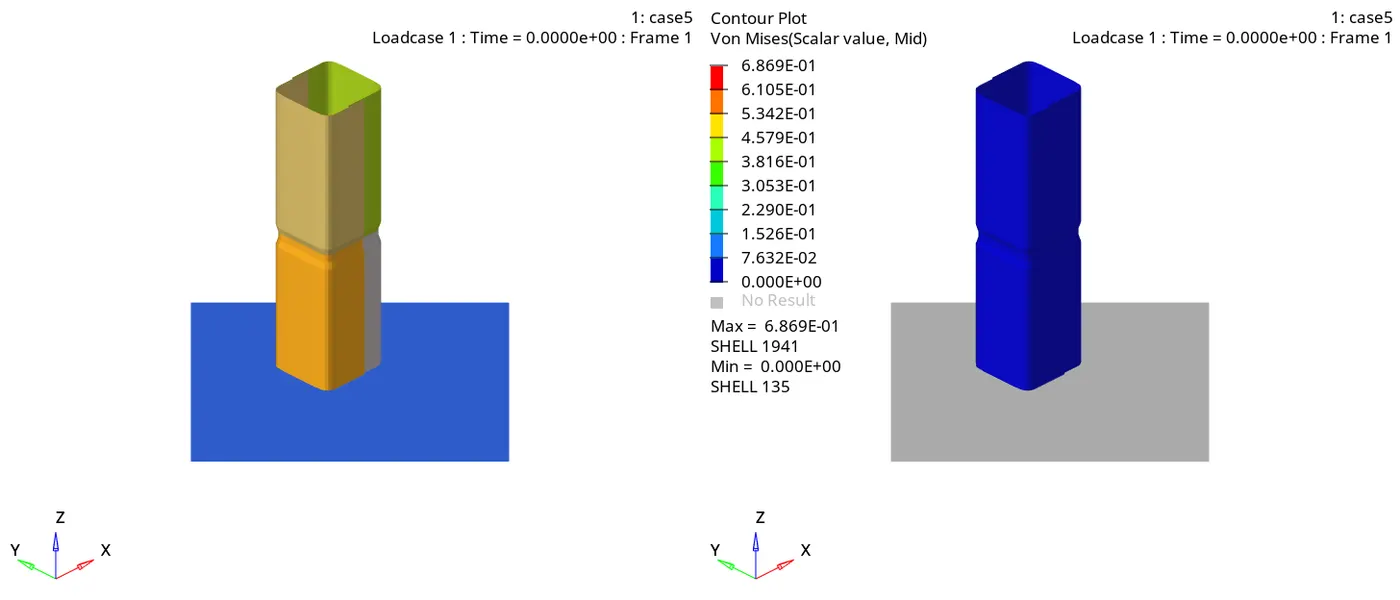
From the above simulation we observe that the crushing starts just below the notch.
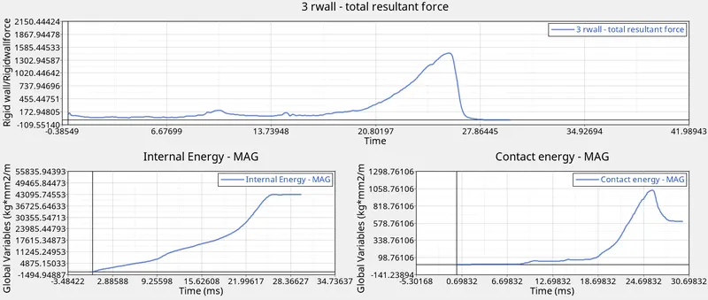
The rwall forces have a peak at 26ms and then drop down as the tube is crushed completely.
CASE 6
We again import the case case4_0000.rad.
We create a notch on opposite faces using translate panel.
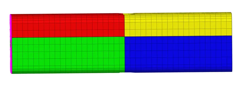
Saving the file as case6_0000.rad and running the analysis.
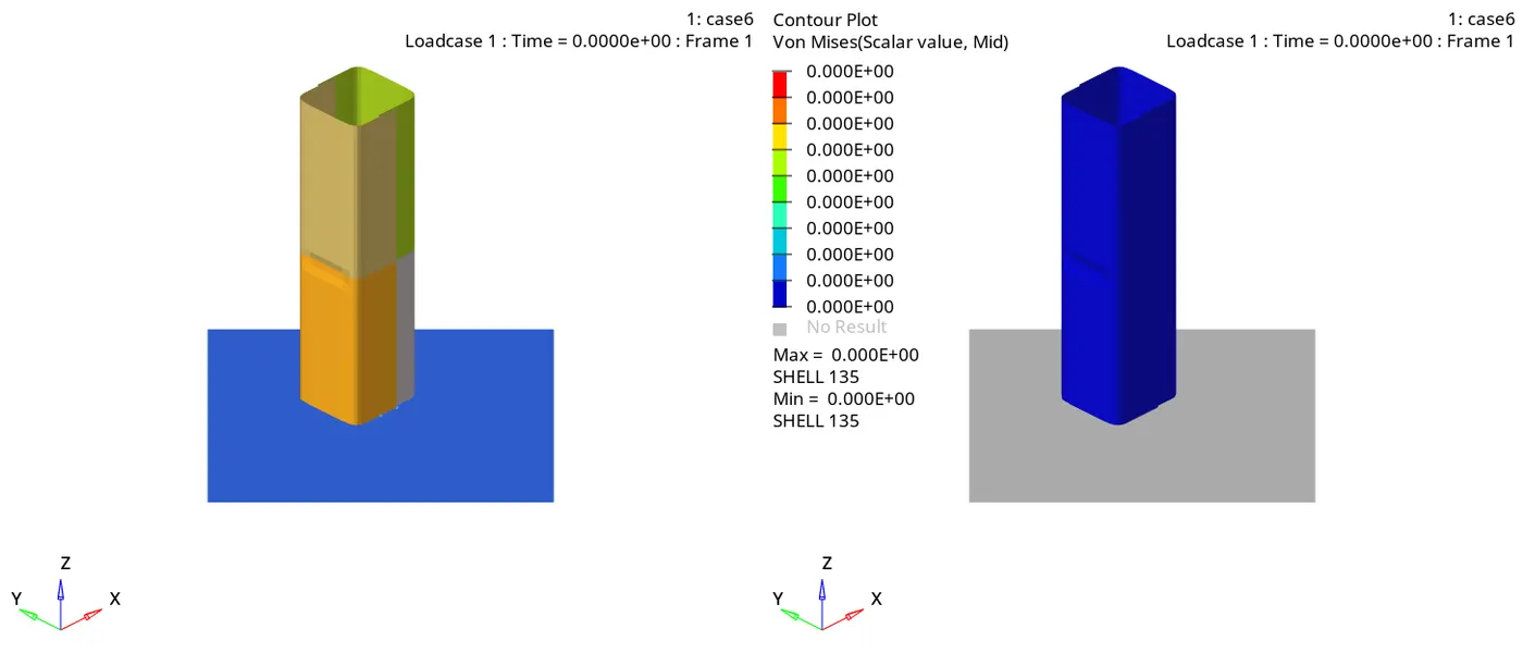
As observed from the simulation, the failure occurs just below the notch. The section below the notch gets deformed first and then the section above the notch deforms.
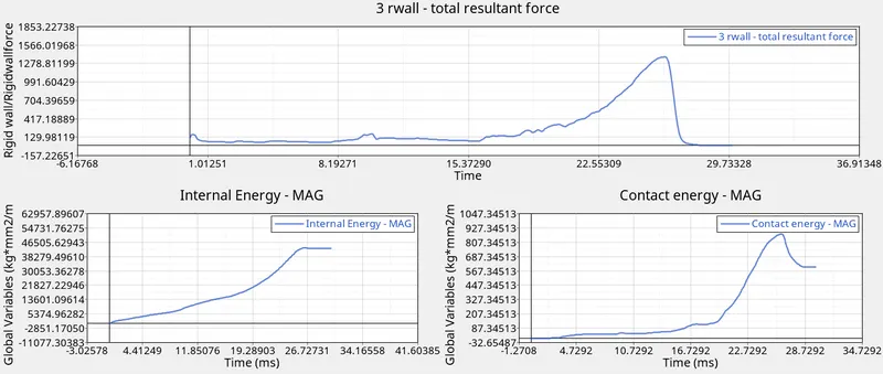
We observe that the rwall forces spike as soon as the contact occurs. The rwall forces peak at about 27ms. Then it drops down as the structure is completely deformed.
TABLE:
|
Case Number |
Cycles |
Time taken |
Energy error |
Mass error |
|
CASE 1 |
83469 |
121.25 s |
-3.8% |
0% |
|
CASE 2 |
83469 |
116.08 s |
-3.8% |
0% |
|
CASE 3 |
128088 |
724.36 s |
-1.6% |
0% |
|
CASE 4 |
152263 |
532.21 s |
-1.6% |
0% |
|
CASE 5 |
134077 |
658.09 s |
-1.3% |
0% |
|
CASE 6 |
128939 |
711.07 s |
-1.3% |
0% |
CONCLUSION:
All the analysis runs had error under-15% and mass error 0%. So the analysis was accepted.
I learned what is function of Inacti in interface types.
I also learned about type 7 and type 11 interfaces.
The notch in structure absorb less forces than the structure without notch. So it is preferable to have no notch in the structure.