Assignment 5-RADIOSS Interfaces & Study of Effect of Notches Challenge
Objective:
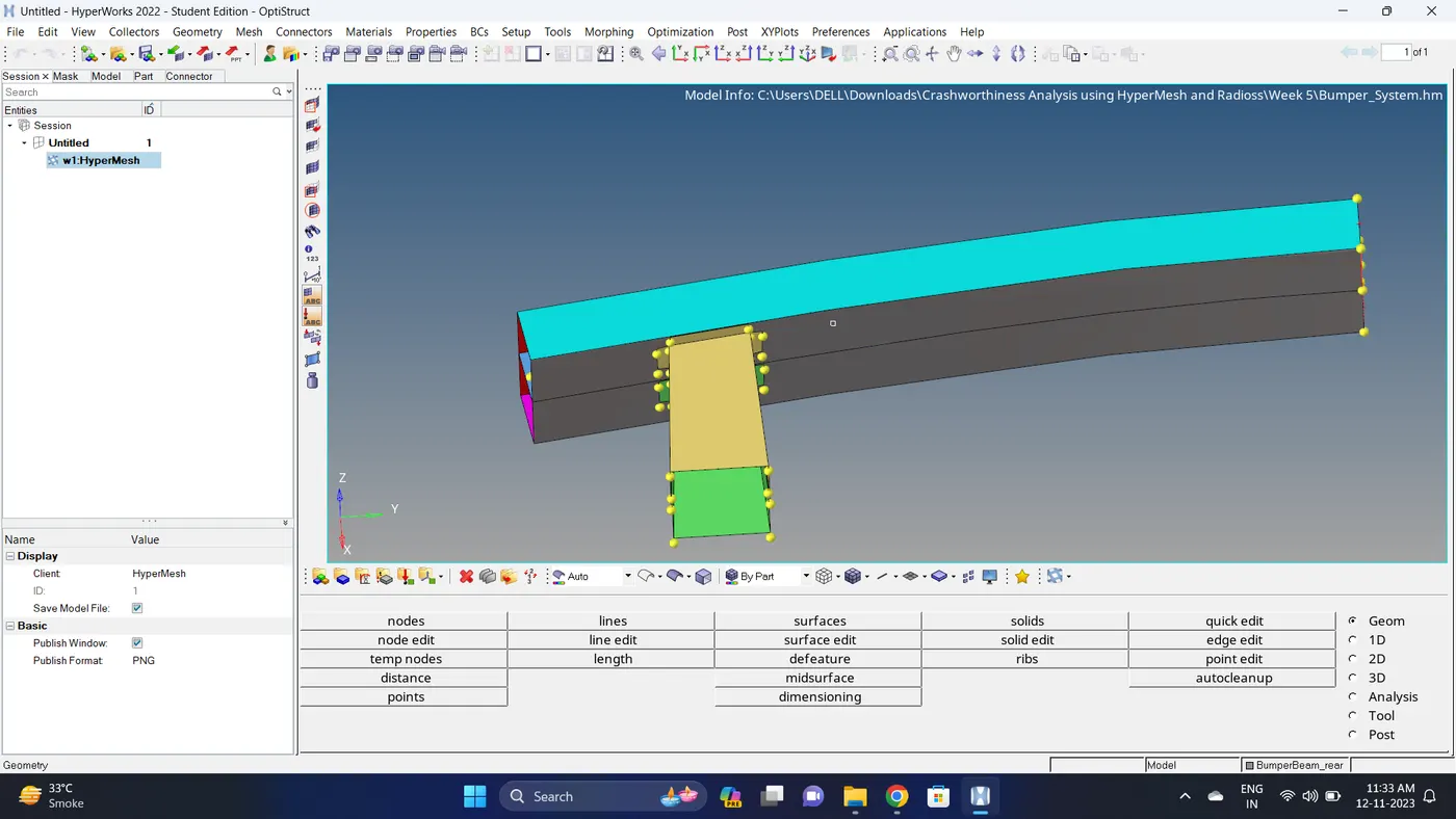
- Create the mesh for bumper assembly,mesh size should be 6mm.
- Run the crash tube model as it is.
- Change the Inacti=6 and run.
- Create the type 11 contact and run.
- Remove both notches and remove boundary condition on rigid body node then run.
- Create a new notch in the middle ,select the whole section and run.
- Create a new notch with nodes only from opposing 2 faces and run.
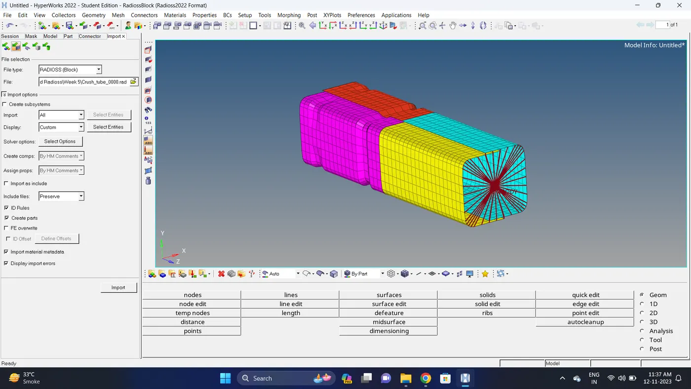
Initial Model Image:
Model 1
Model 2
Procedure:
Model 1
1. Open the Model in Hypermesh.
2. Check for geometry.
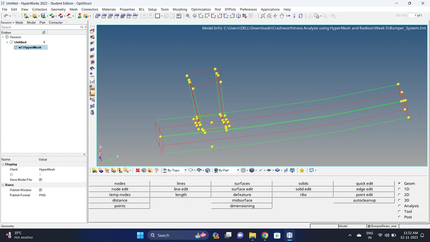
3. Do geometry cleanup.
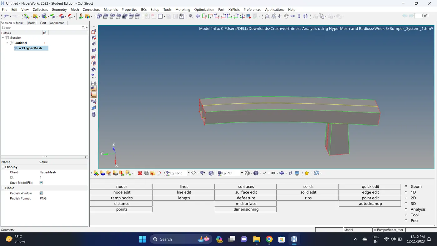
4. Go to 2D - Automesh - give mesh size 6 - and mesh the model.
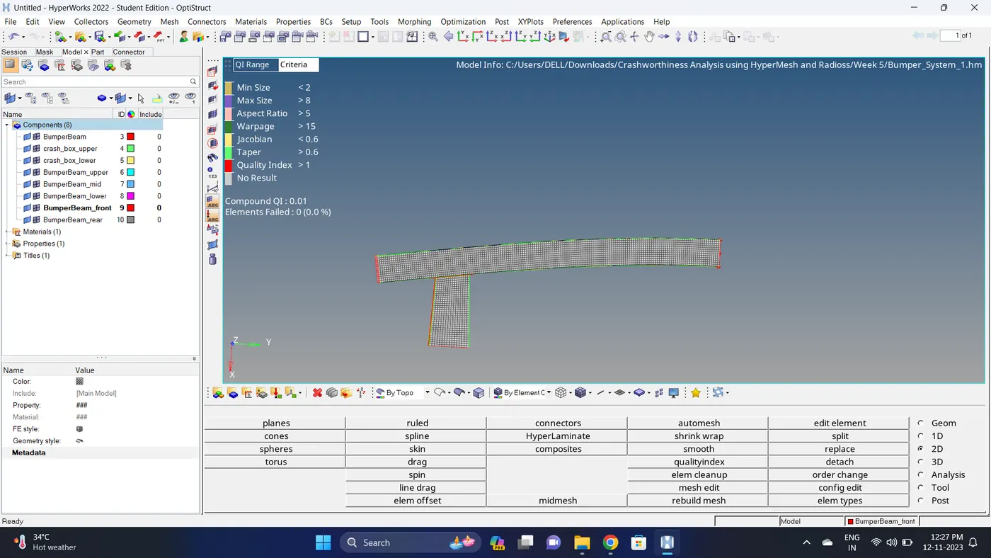
5. Do the final checks - Free edges - Duplicate element and Normals.
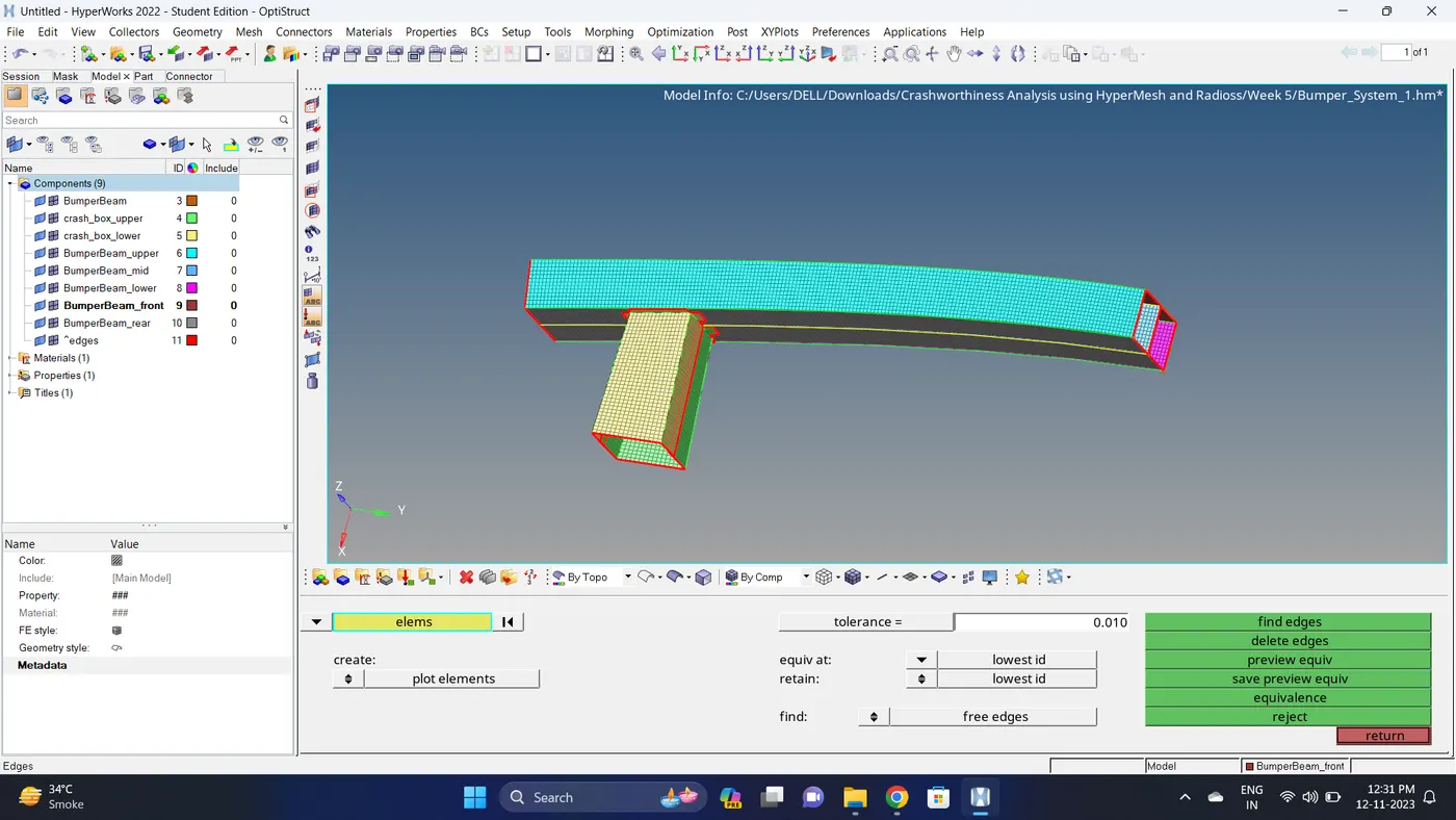
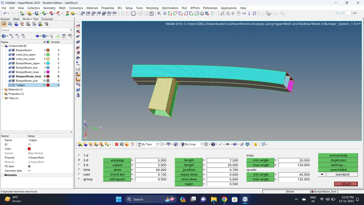
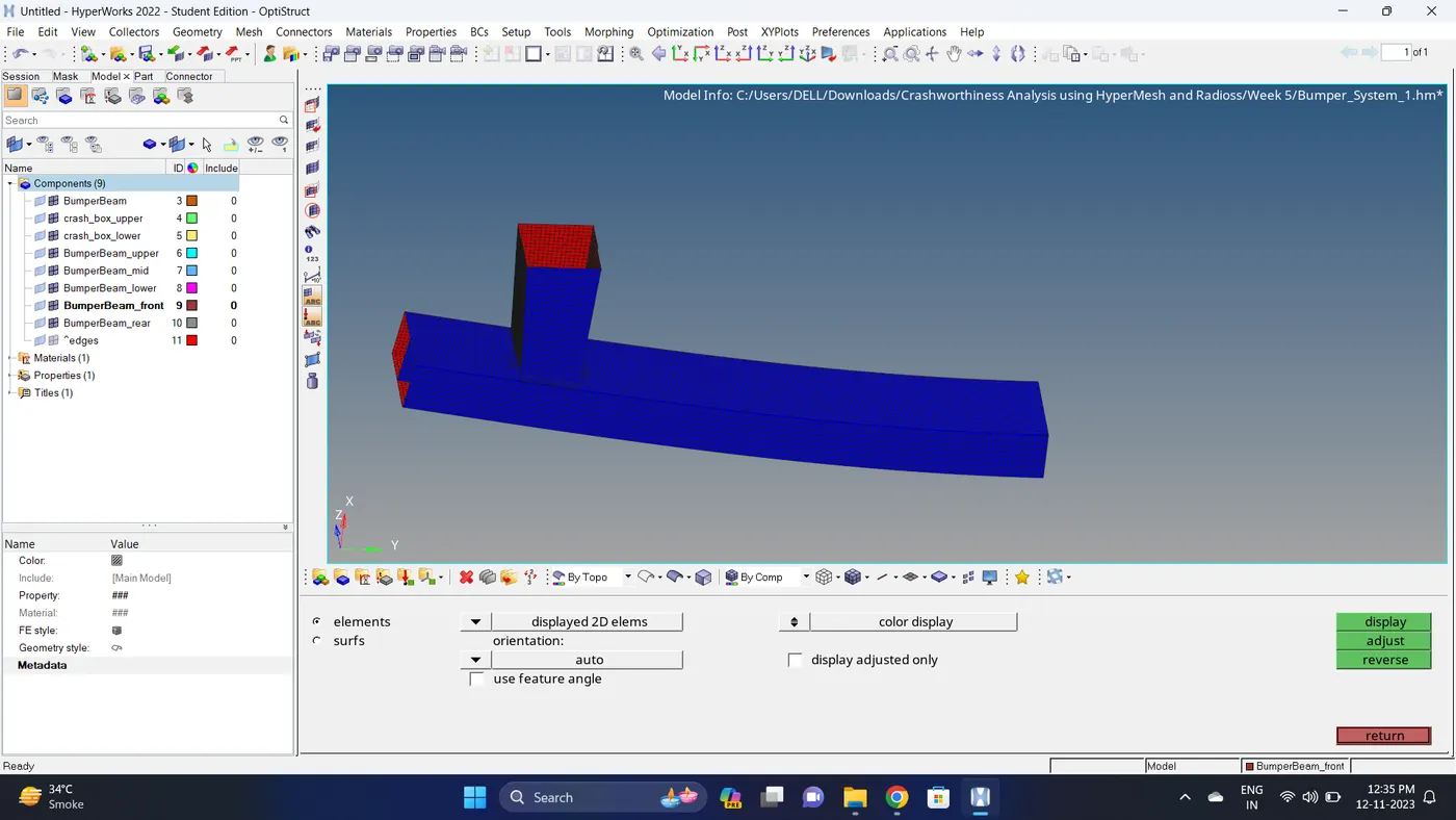
6. Model 1 is Complete.
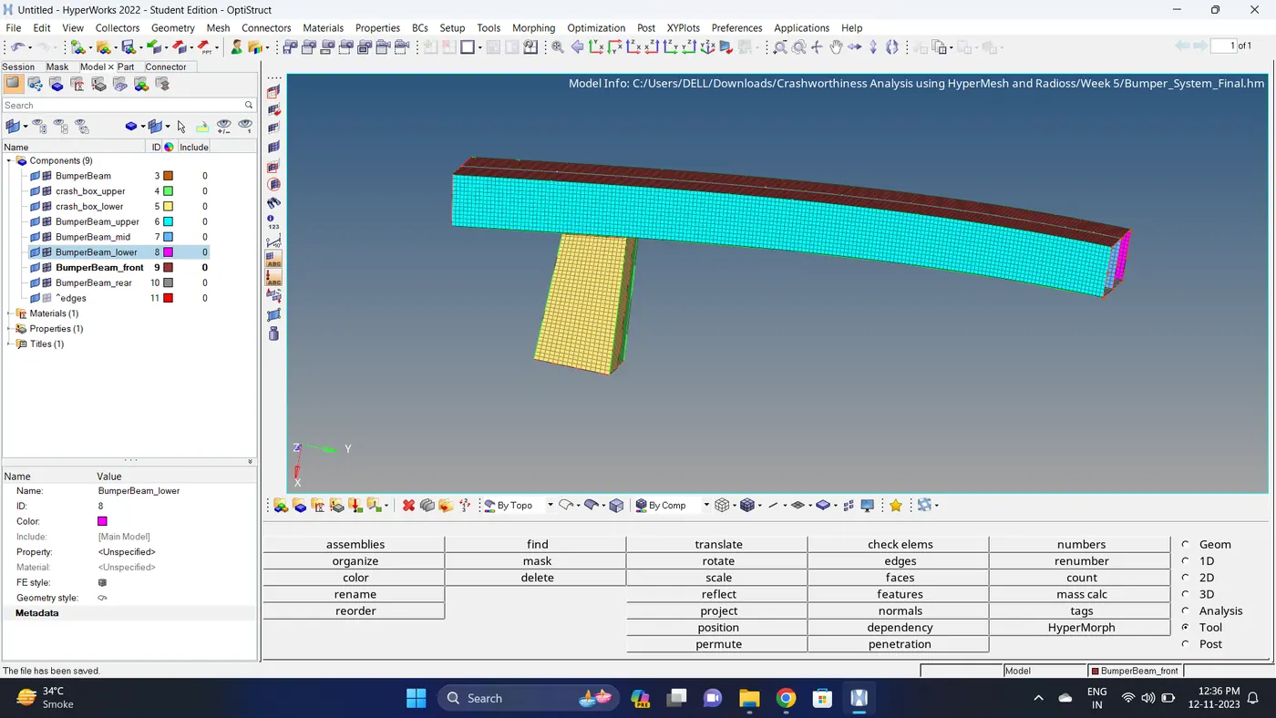
Model 2
Case 1:
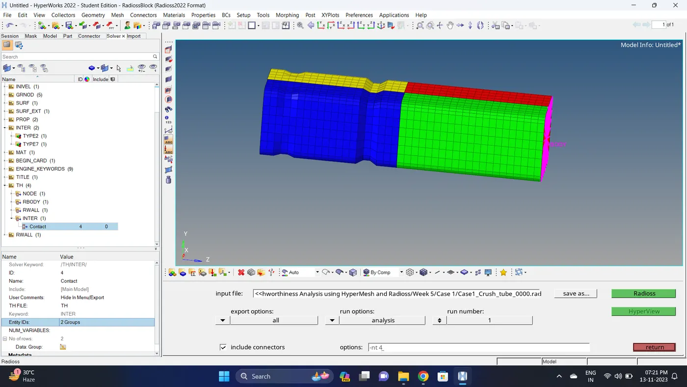
1. Import the Crush_tube_0000.rad file.
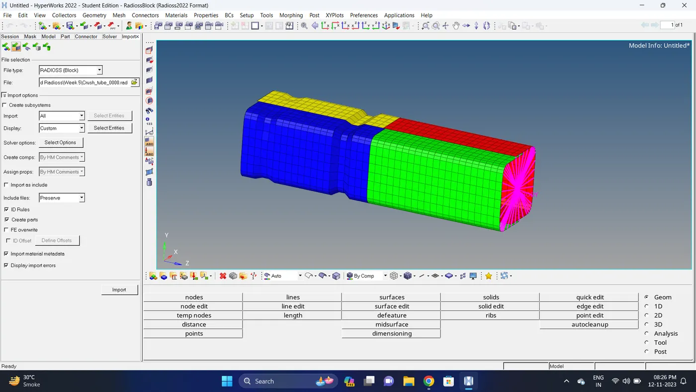
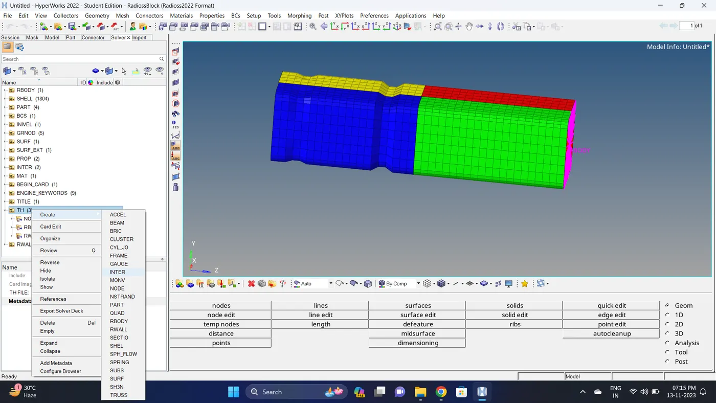
2. Go to the Solver deck - Create a new TH file for INTER and Select the TYPE2 & TYPE7 Contact Interface.
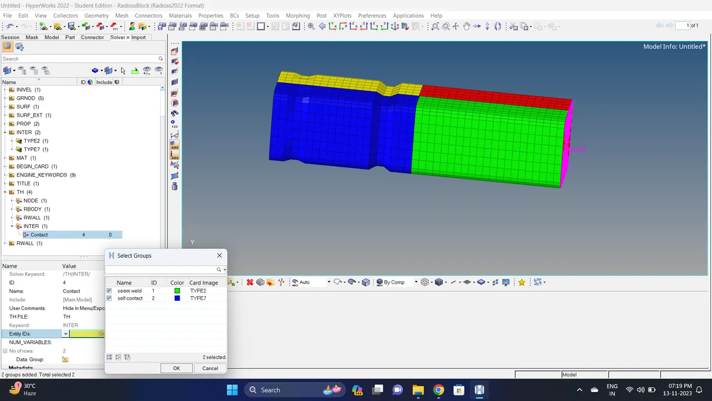
3. Run the simulation.
Go to Analysis - Radioss - click on save as, Rename the file to Case1_Crush_tube and at the end type .rad - Ensure that export option is set to all and Include connectors is tick - Click Radioss to run the simulation.
Note: If the stimulation is not running it taking time then copy the given input 0000.rad and 0001.rad file to folder, Rename both the file to Case1_Crush_tube, click on the 0000.rad file click save and overwrite it.
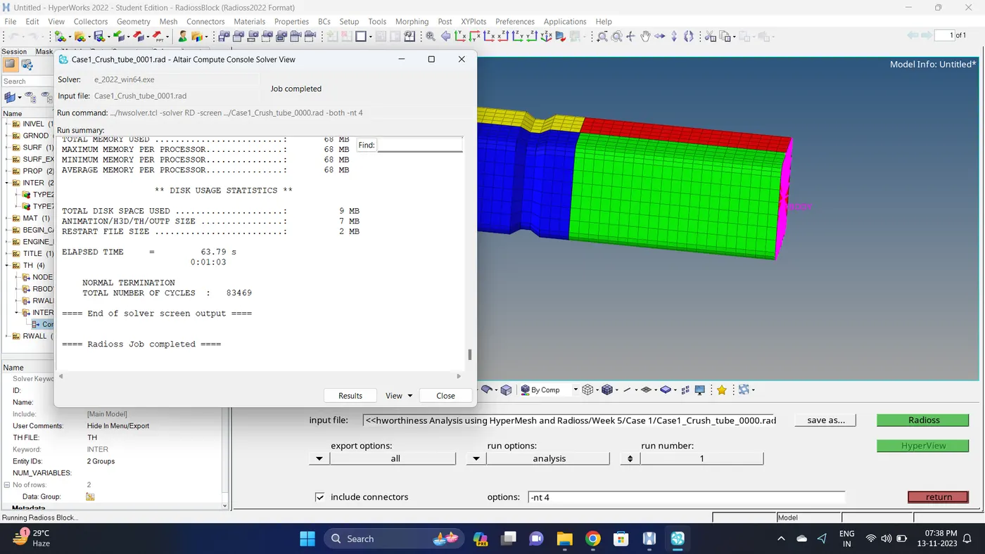
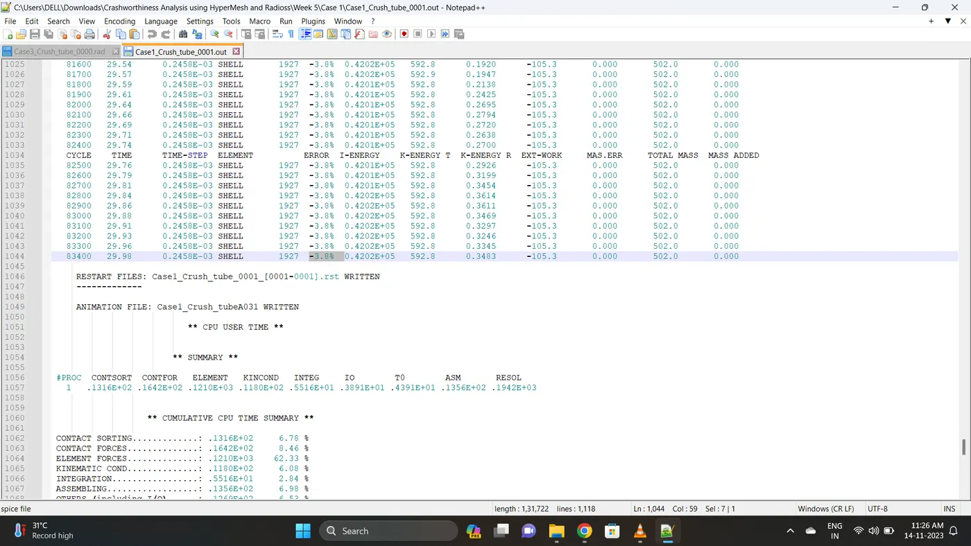
4. Open 0001.out file in notepad ++ and check the maximum total energy error and mass error.
The torelance for the energy error is -15 to +5 % and mass error is upto 2 %.
Energy error is -3.8% & Mass error is 0%.
5. Open the Hyperwork in Hypergraph 2D view.
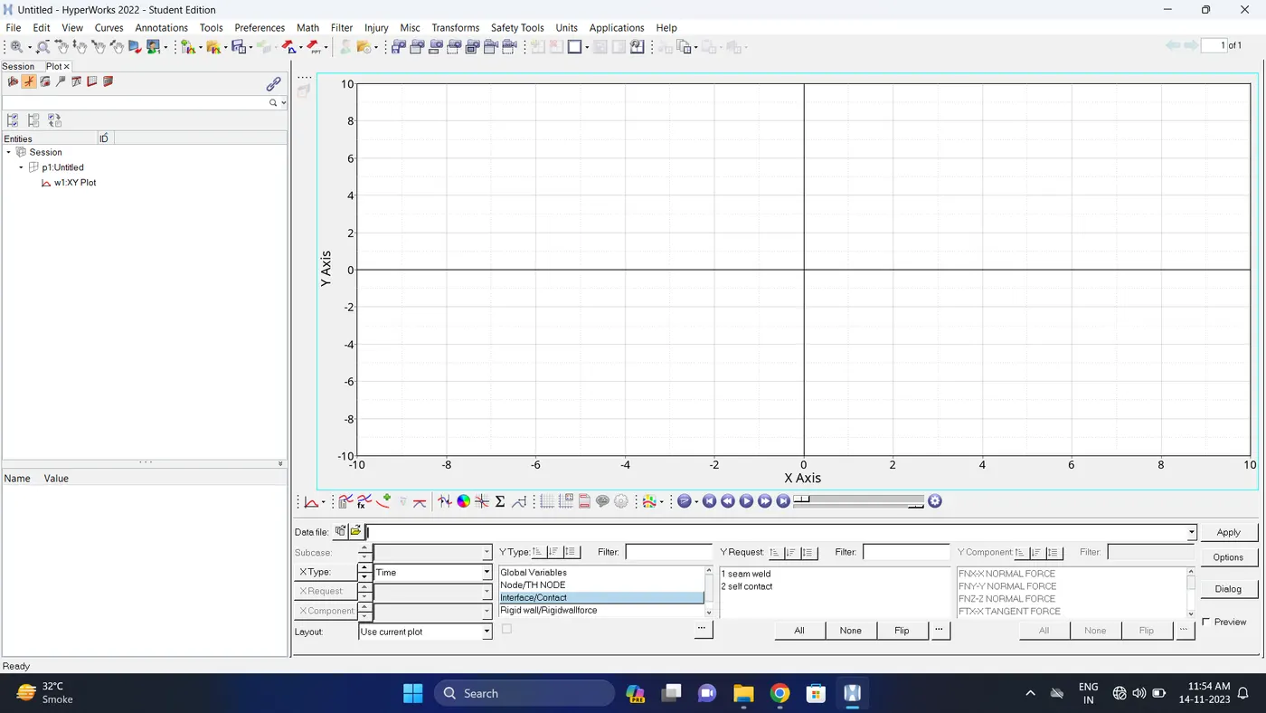
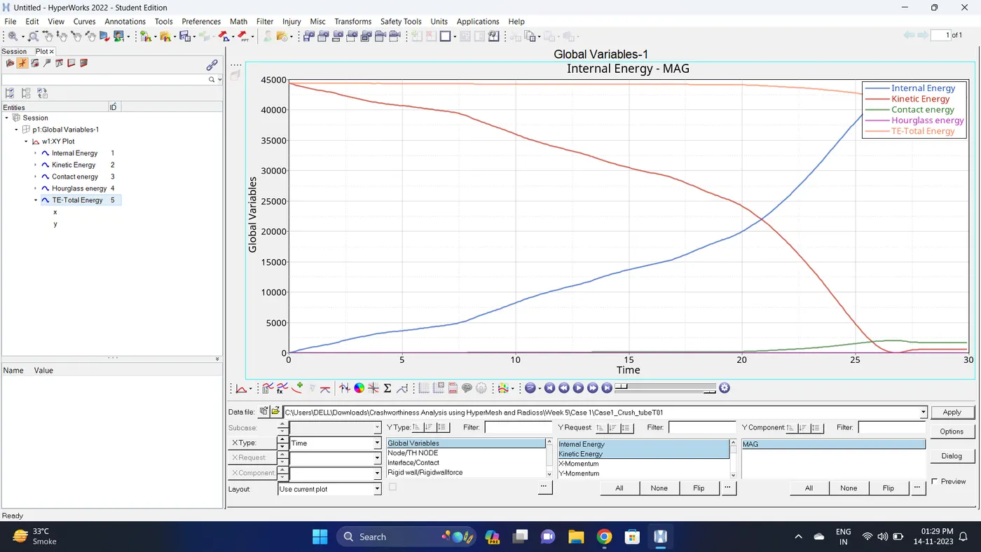
6. Open the T01 file from case_1 and select the Global Variable - Internal energy, Kinetic energy, Contact Energy, Hourglass Energy and Total Energy - Click apply to plot the graph.
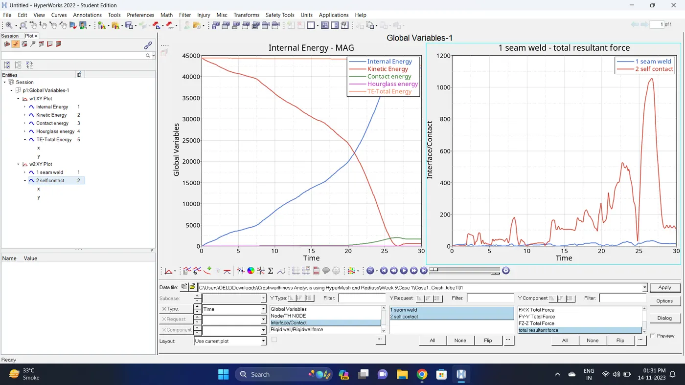
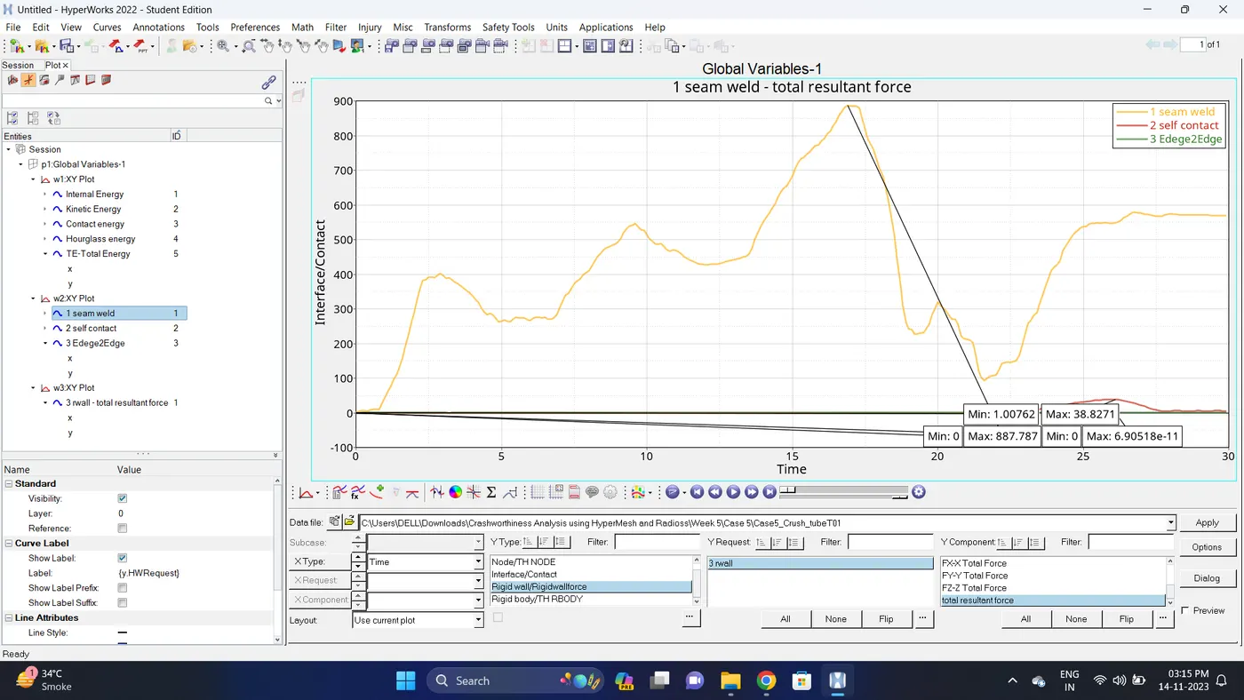
7. Change the windows page layout to 2 and in second window plot the Interface/Contact forces graph.
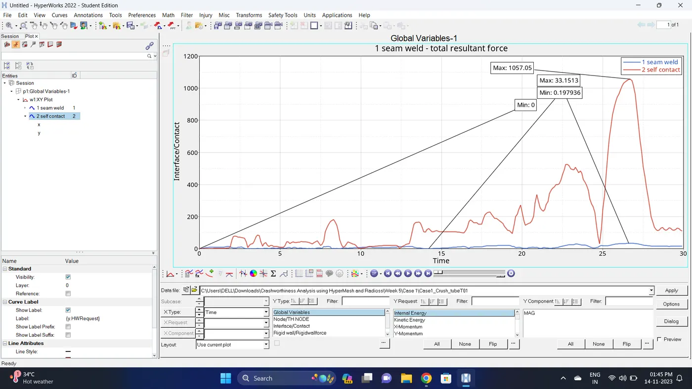
To plot the graph select Interface/Contact - Select all the contact types - total resultant force - click apply.
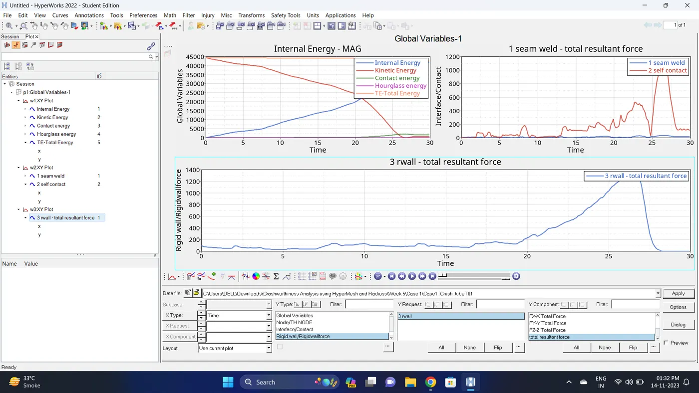
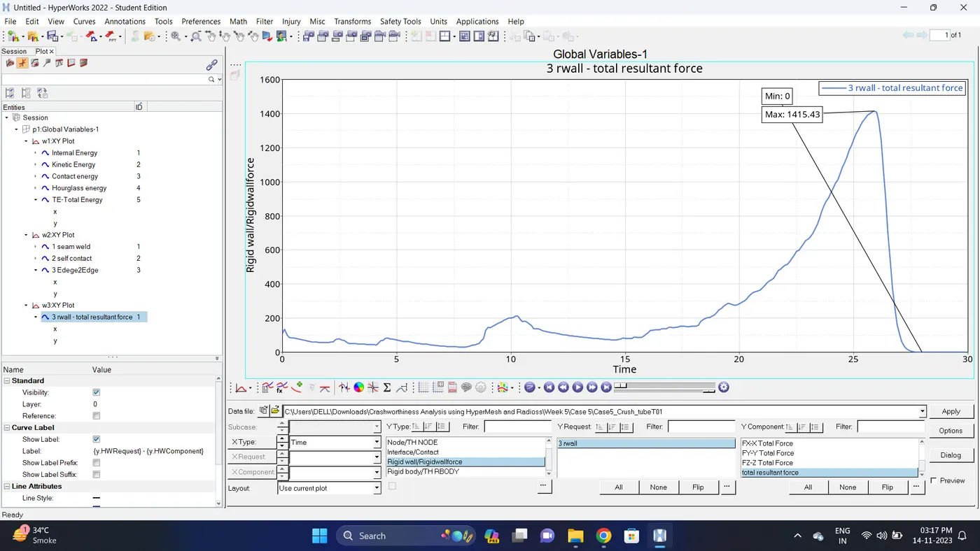
8. Change the windows page layout to 3 and in Third window plot the rigid wall forces graph.
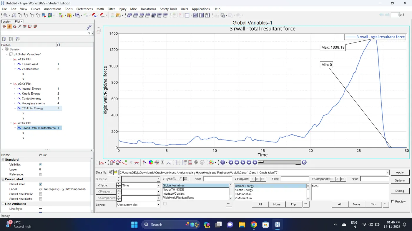
To plot graph select Rigid wall/Rwall-forces - 3 rwall - total resultant force - click apply
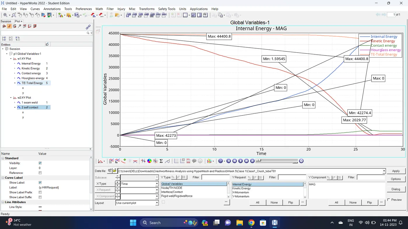
9. Note down the minimum and maximum value of various Energy by right click on any energy - Single curve math - Min Note. similarly do for maximum
Note: after getting graph reading turn off that graph and do next reading.
| Sr. no | Name | Minimum | Maximum |
| 1 | Internal energy | 0 | 42273 |
| 2 | Kinetic energy | 1.59545 | 44400.8 |
| 3 | Contact Energy | 0 | 2029.77 |
| 4 | Hourglass Energy | 0 | 0 |
| 5 | Total Energy | 42274.4 | 44400.8 |
| 6 | Seam Weld (Type2 Contact) Total Resultant Force | 0.197936 | 33.1513 |
| 7 | Self Contact (Type7 Contact) Total Resultant Force | 0 | 1057.05 |
| 8 | Rigid Wall Forces (Total Resultant Force) | 0 | 1338.18 |
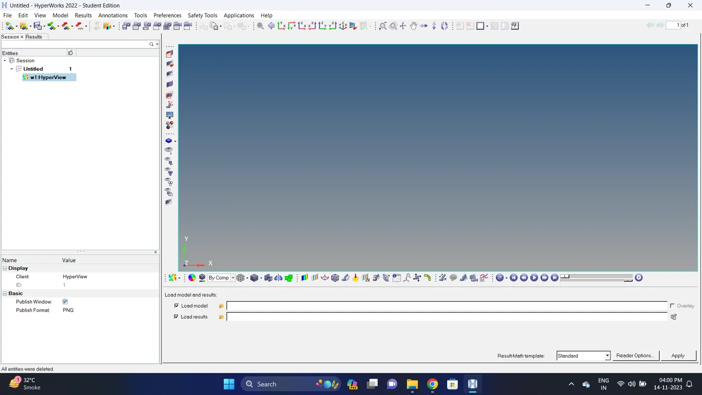
10. Open the Hyperwork in Hyperview view.
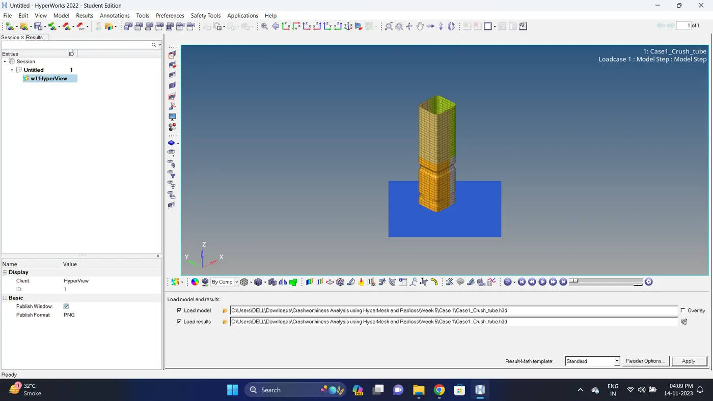
11. Import the .h3d file.
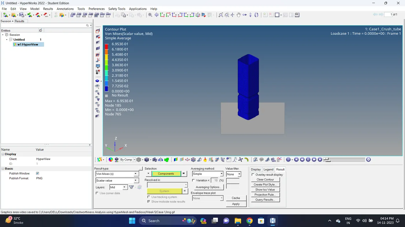
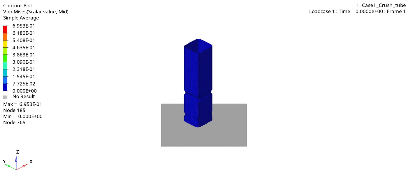
12. Go to the contour - change result type to Von mises (s), averaging method to simple, click on apply and play the animation.
Maximum stress = 0.6953 and Minimum stess is 0.
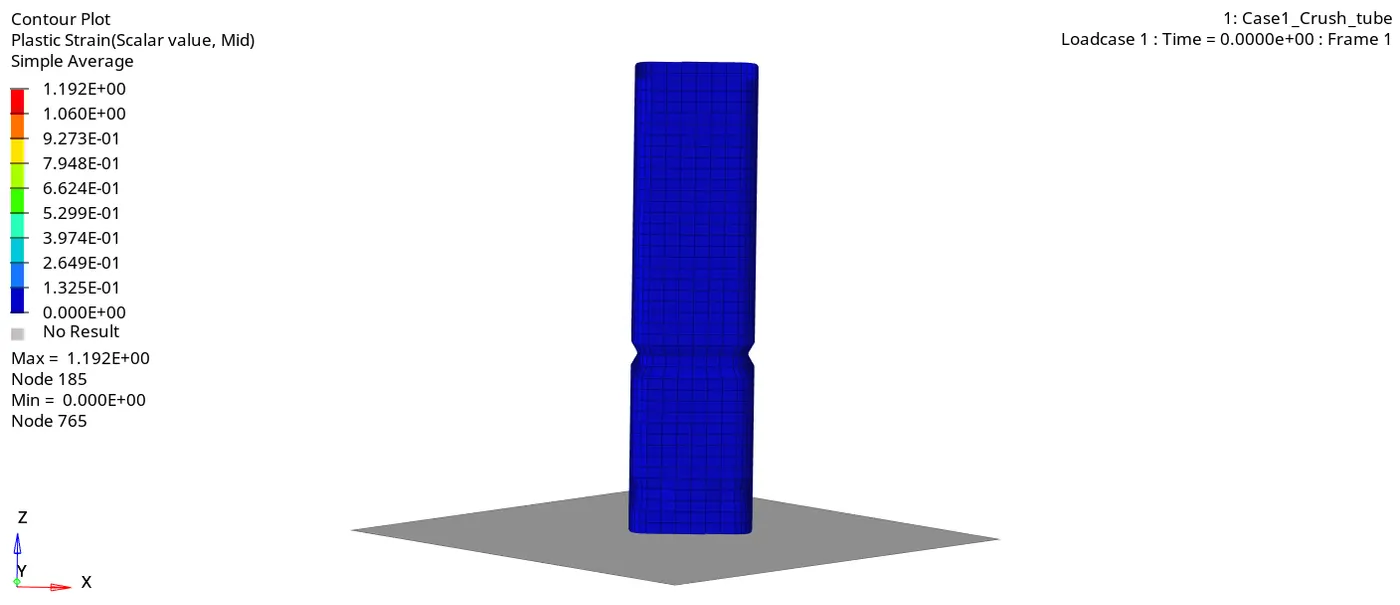
13. Change the windows page layout to 2 and in second window similarly plot plastic strain.
Maximum strain is 1.192 and Minimum strain is 0.
Case 2:
1. Import the Case1_Crush_tube_0000.rad file.
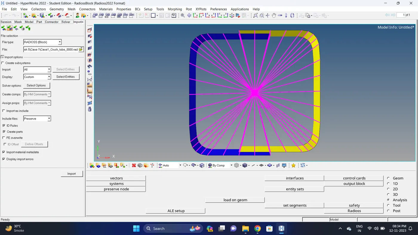
2. Go to the Solver Deck - INTER - TYPE 7 - Change Inactiv= 0 to Inactiv= 6.
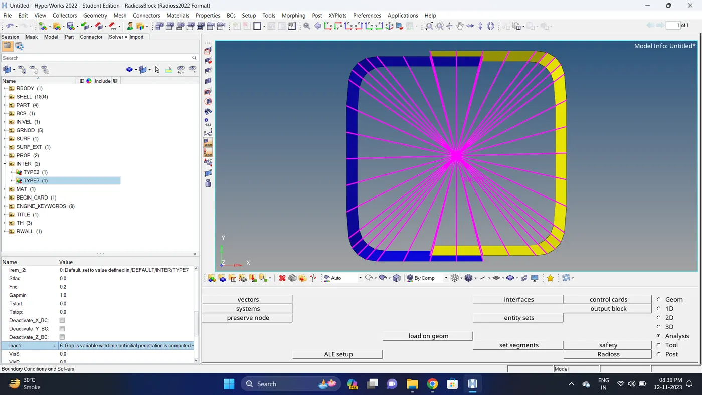
3. Run the simulation.
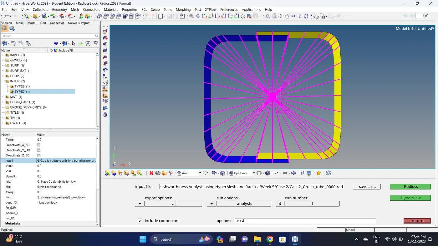
Go to Analysis - Radioss - click on save as, Rename the file to Case2_Crush_tube and at the end type .rad - Ensure that export option is set to all and Include connectors is tick - Click Radioss to run the simulation.
Note: If the stimulation is not running it taking time then copy the given input 0000.rad and 0001.rad file to folder, Rename both the file to Case2_Crush_tube, click on the 0000.rad file click save and overwrite it.
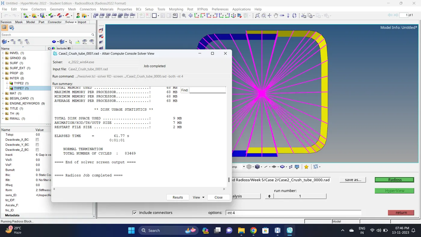
4. Open 0001.out file in notepad ++ and check the maximum total energy error and mass error.
The torelance for the energy error is -15 to +5 % and mass error is upto 2 %.
Energy error is -3.8% & Mass error is 0%.
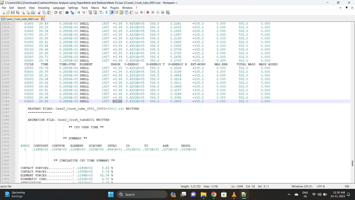
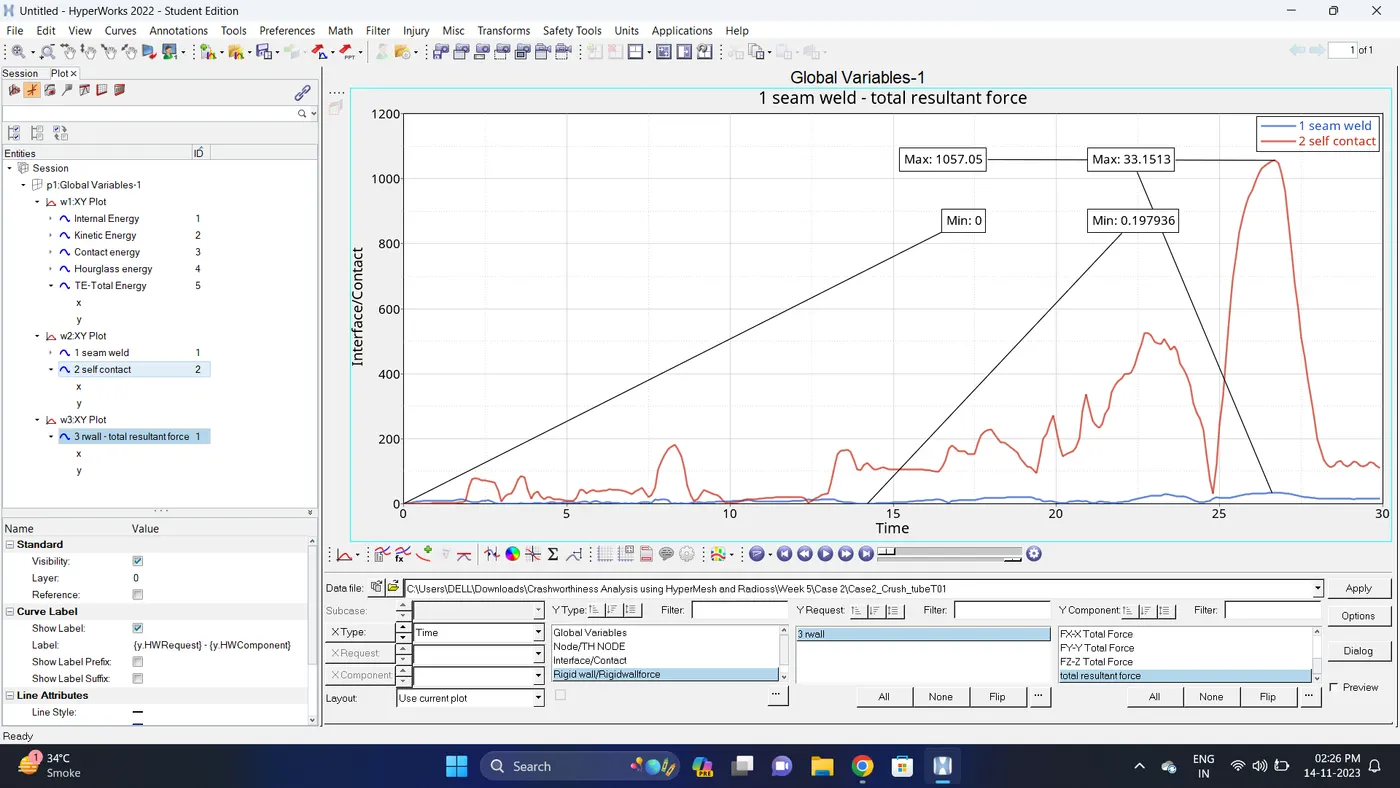
5. Open the Hyperwork in Hypergraph 2D view.
6. Open the T01 file from case_2 and select the Global Variable - Internal energy, Kinetic energy, Contact Energy, Hourglass Energy and Total Energy - Click apply to plot the graph.
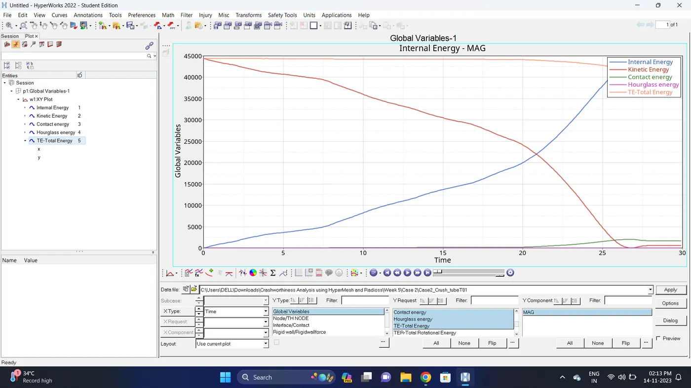
7. Change the windows page layout to 2 and in second window plot the Interface/Contact forces graph.
To plot the graph select Interface/Contact - Select all the contact types - total resultant force - click apply.
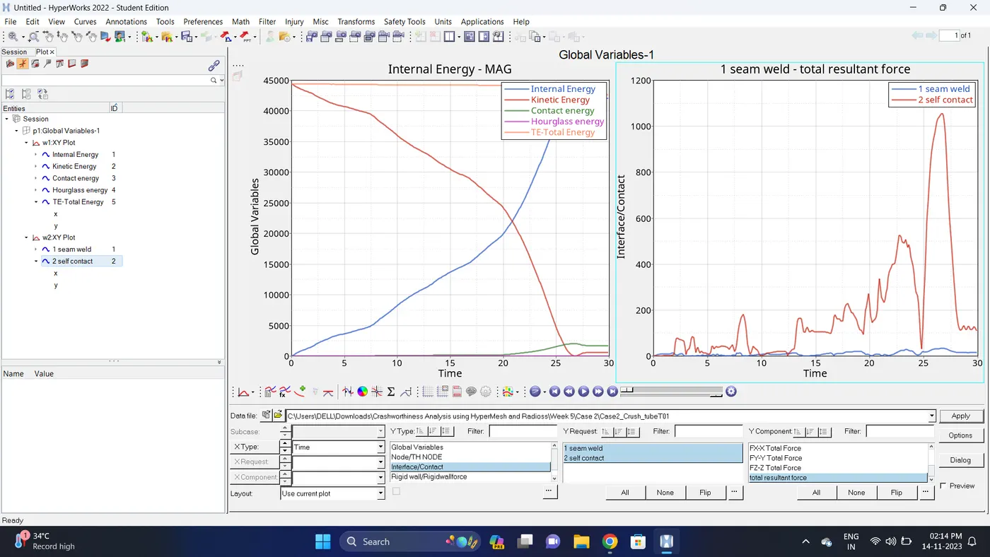
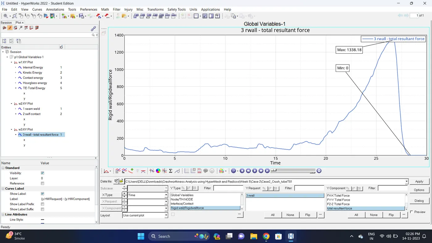
8. Change the windows page layout to 3 and in Third window plot the rigid wall forces graph.
To plot graph select Rigid wall/Rwall-forces - 3 rwall - total resultant force - click apply.
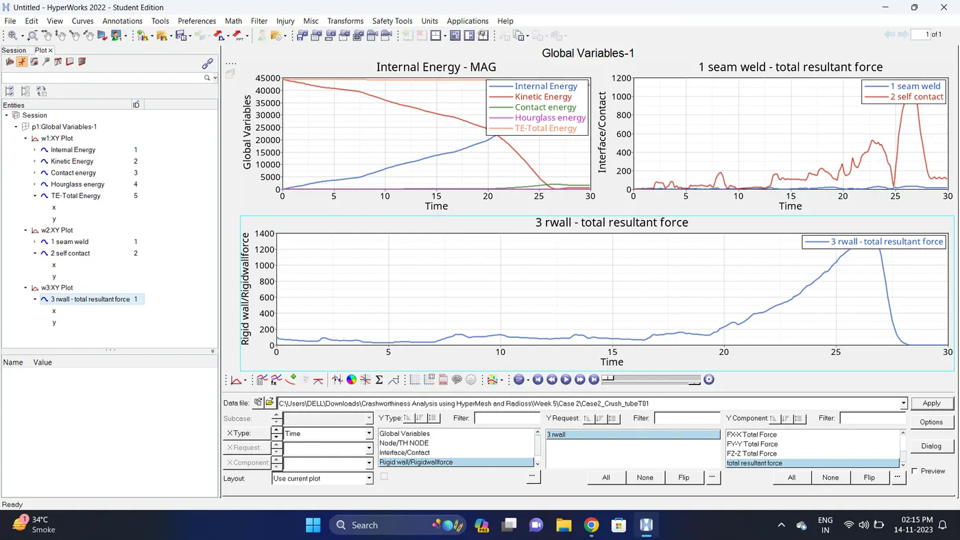
9. Note down the minimum and maximum value of various Energy by right click on any energy - Single curve math - Min Note. similarly do for maximum
Note: after getting graph reading turn off that graph and do next reading.
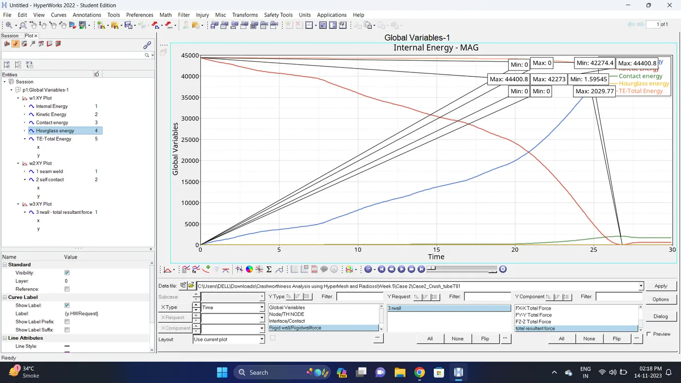
| Sr. no | Name | Minimum | Maximum |
| 1 | Internal energy | 0 | 42273 |
| 2 | Kinetic energy | 1.59545 | 44400.8 |
| 3 | Contact Energy | 0 | 2029.77 |
| 4 | Hourglass Energy | 0 | 0 |
| 5 | Total Energy | 42274.4 | 44400.8 |
| 6 | Seam Weld (Type2 Contact) | 0.197936 | 33.1513 |
| 7 | Self Contact (Type7 Contact) | 0 | 1057.05 |
| 8 | Rigid Wall Forces (Total Resultant Force) | 0 | 1338.18 |
10. Import the .h3d file.
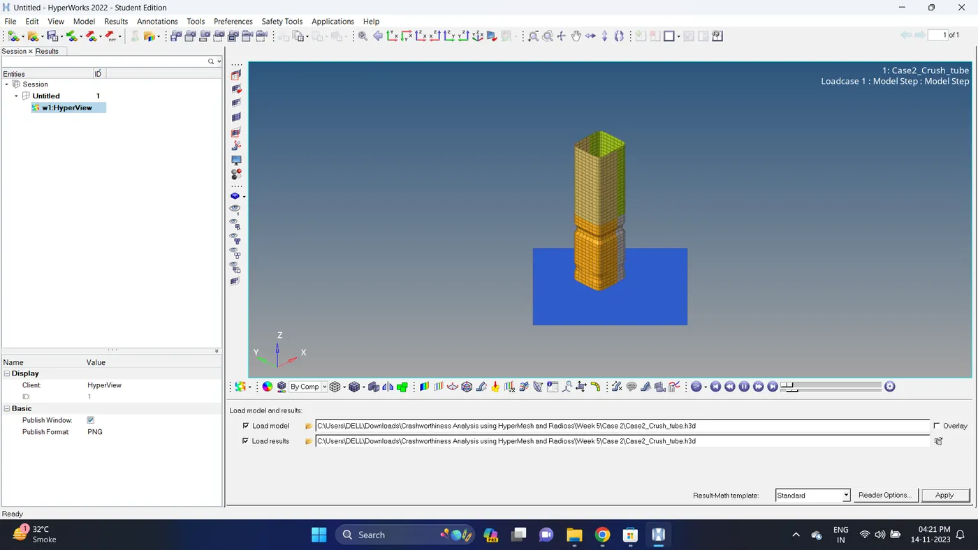
11. Go to the contour - change result type to Von mises (s), averaging method to simple, click on apply and play the animation.
Maximum stress = 0.6953 and Minimum stess is 0.
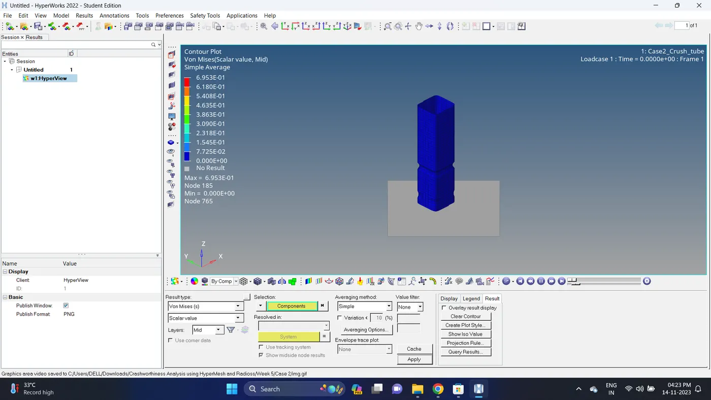
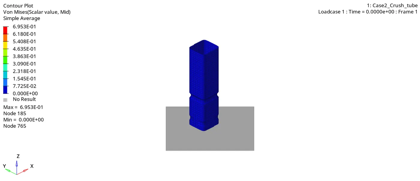
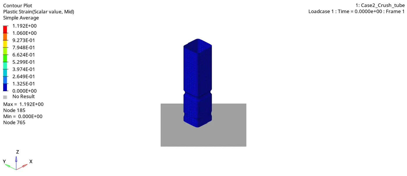
12. Similarly plot plastic strain.
Maximum strain is 1.192 and Minimum strain is 0.
Case 3:
1. Import the Case2_Crush_tube_0000.rad file.
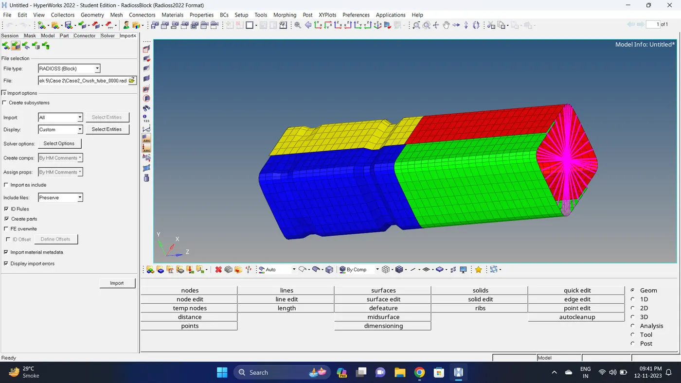
2. Go to the Solver deck - INTER - Right click on INTER and create TYPE 11 Contact.
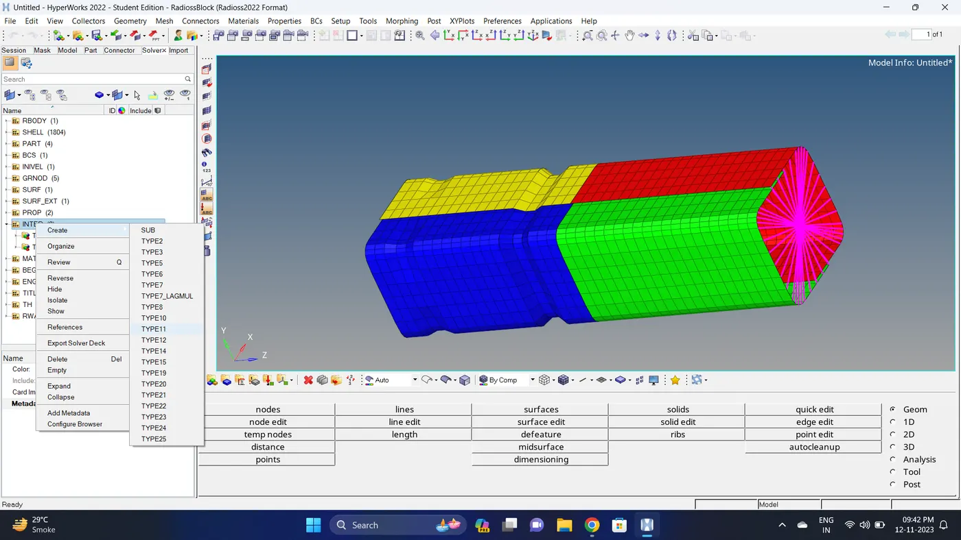
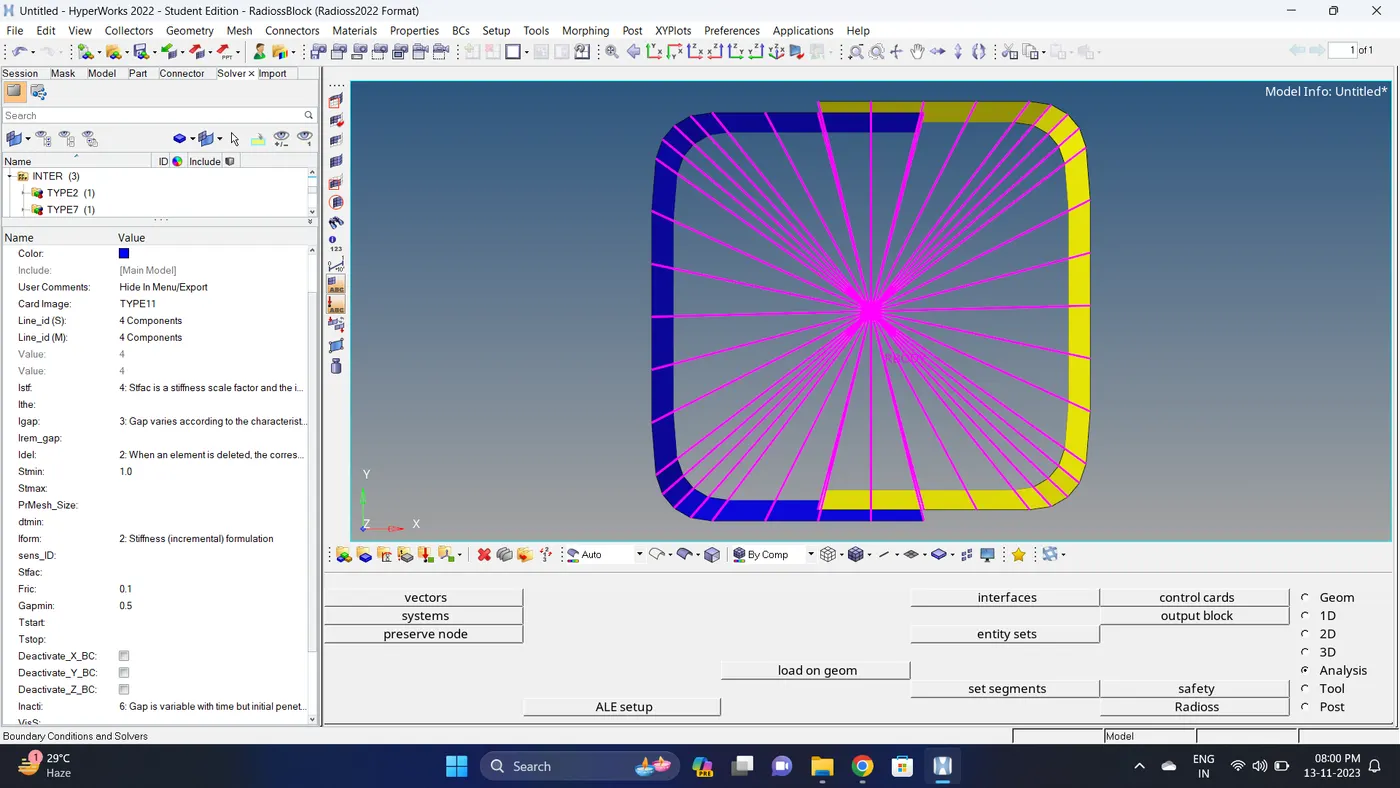
3. Go to Solver deck - TH - INTER. Add Edge2Edge contact in Entity IDs.
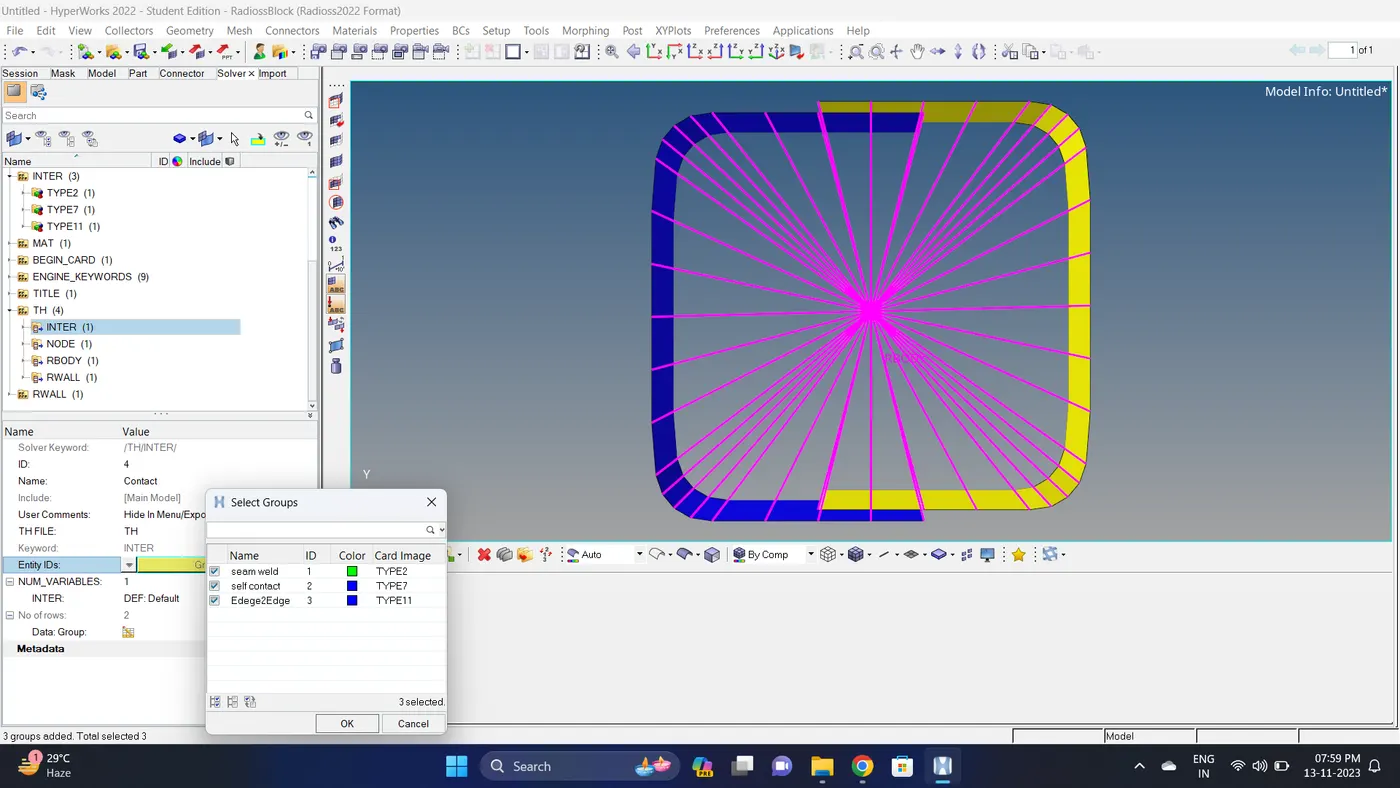
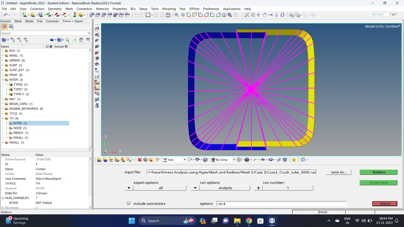
4. Run the simulation.
Go to Analysis - Radioss - click on save as, Rename the file to Case3_Crush_tube and at the end type .rad - Ensure that export option is set to all and Include connectors is tick - Click Radioss to run the simulation.
Note: If the stimulation is not running it taking time then copy the given input 0000.rad and 0001.rad file to folder, Rename both the file to Case3_Crush_tube, click on the 0000.rad file click save and overwrite it.
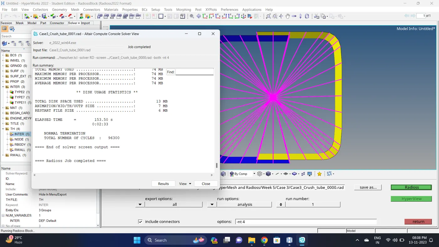
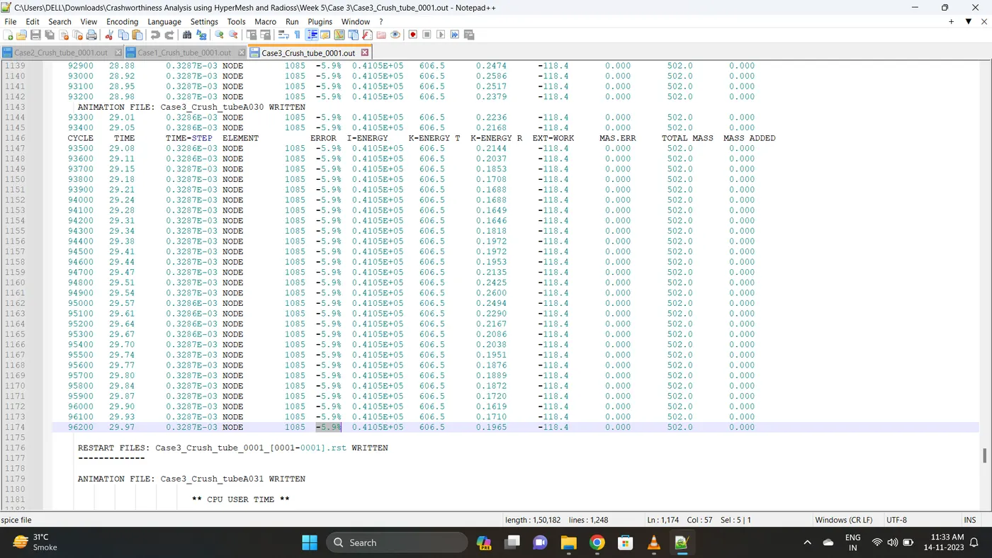
5. Open 0001.out file in notepad ++ and check the maximum total energy error and mass error.
The torelance for the energy error is -15 to +5 % and mass error is upto 2 %.
Energy error is -5.9% & Mass error is 0%.
6. Open the Hyperwork in Hypergraph 2D view.
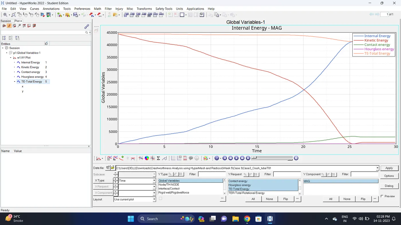
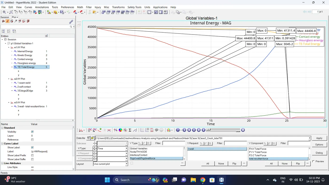
7. Open the T01 file from case_3 and select the Global Variable - Internal energy, Kinetic energy, Contact Energy, Hourglass Energy and Total Energy - Click apply to plot the graph.
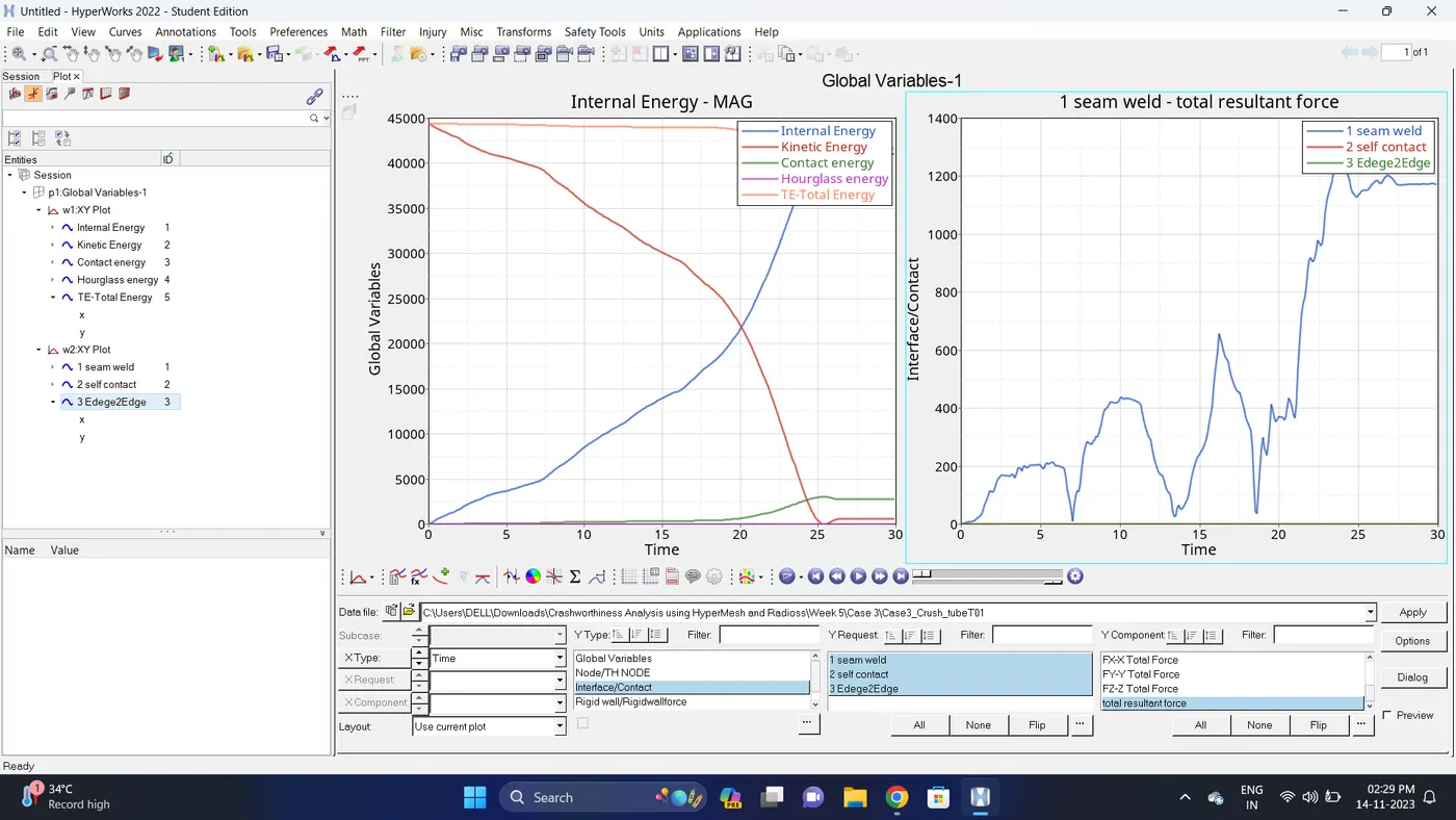
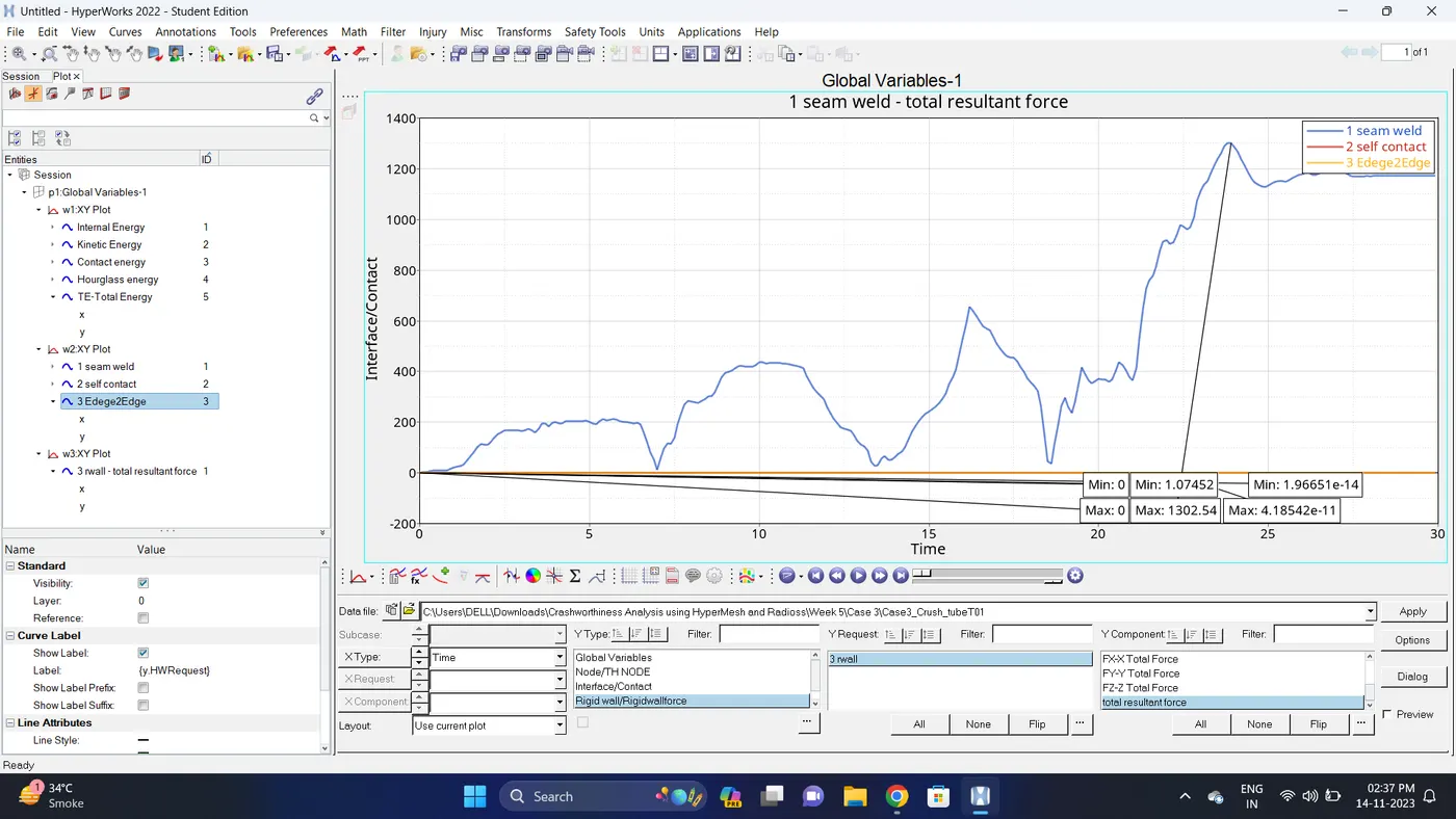
8. Change the windows page layout to 2 and in second window plot the Interface/Contact forces graph.
To plot the graph select Interface/Contact - Select all the contact types - total resultant force - click apply
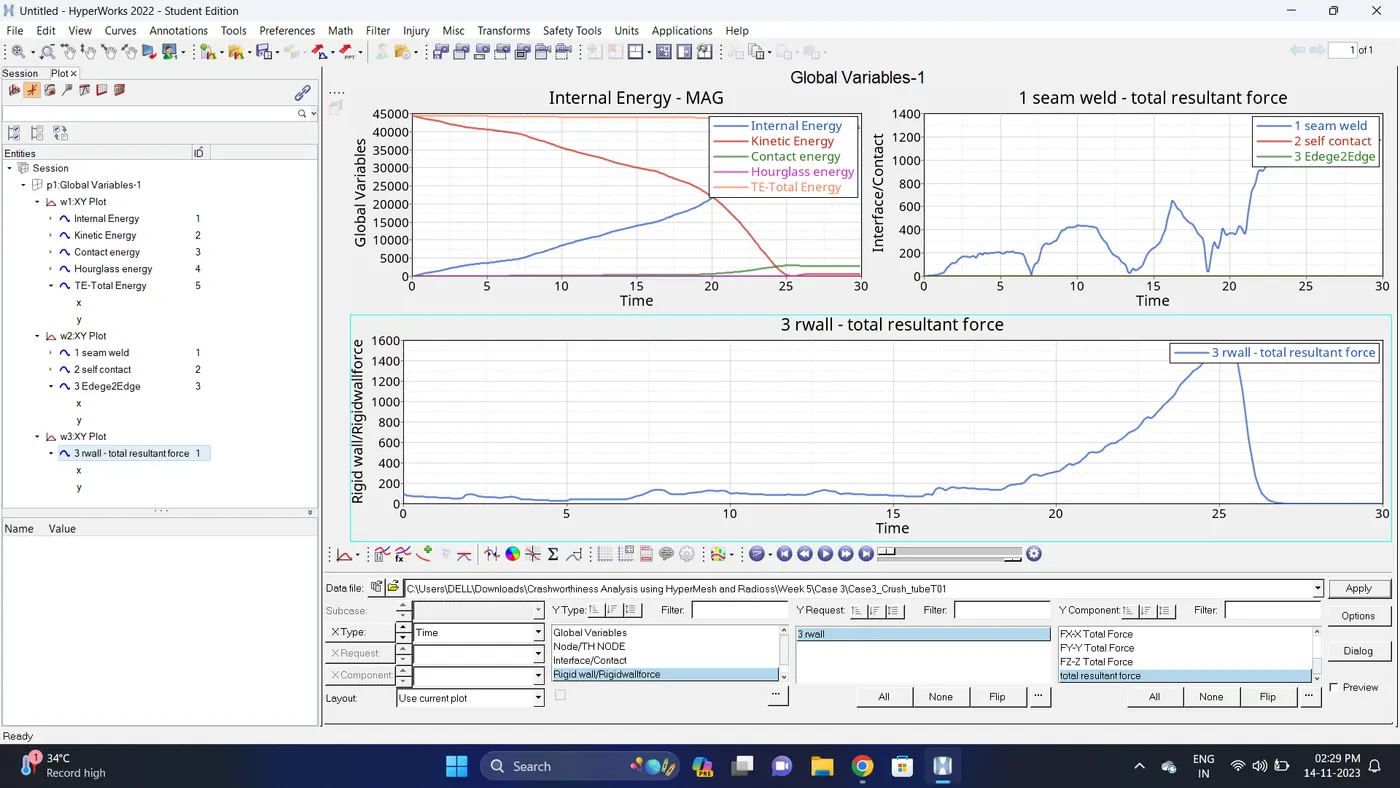
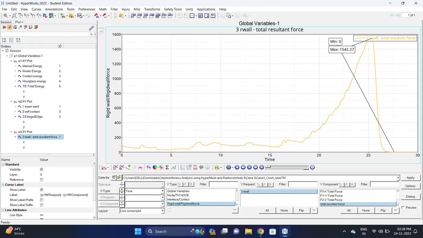
9. Change the windows page layout to 3 and in Third window plot the rigid wall forces graph.
To plot graph select Rigid wall/Rwall-forces - 3 rwall - total resultant force - click apply.
10. Note down the minimum and maximum value of various Energy by right click on any energy - Single curve math - Min Note. similarly do for maximum.
Note: after getting graph reading turn off that graph and do next reading.
| Sr. no | Name | Minimum | Maximum |
| 1 | Internal energy | 0 | 41311 |
| 2 | Kinetic energy | 0.391428 | 44400.8 |
| 3 | Contact Energy | 0 | 3045.2 |
| 4 | Hourglass Energy | 0 | 0 |
| 5 | Total Energy | 41311.4 | 44400.8 |
| 6 | Seam Weld (Type2 Contact) | 1.07452 | 1302.54 |
| 7 | Self Contact (Type7 Contact) | 0 | 0 |
| 8 | Edge2Edge (Type11 Contact) | 1.96651e-14 | 4.18542e-11 |
| 9 | Rigid Wall Forces (Total Resultant Force) | 0 | 1542.27 |
11. Import the .h3d file.
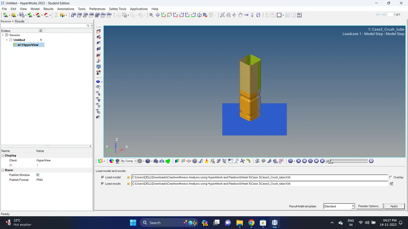
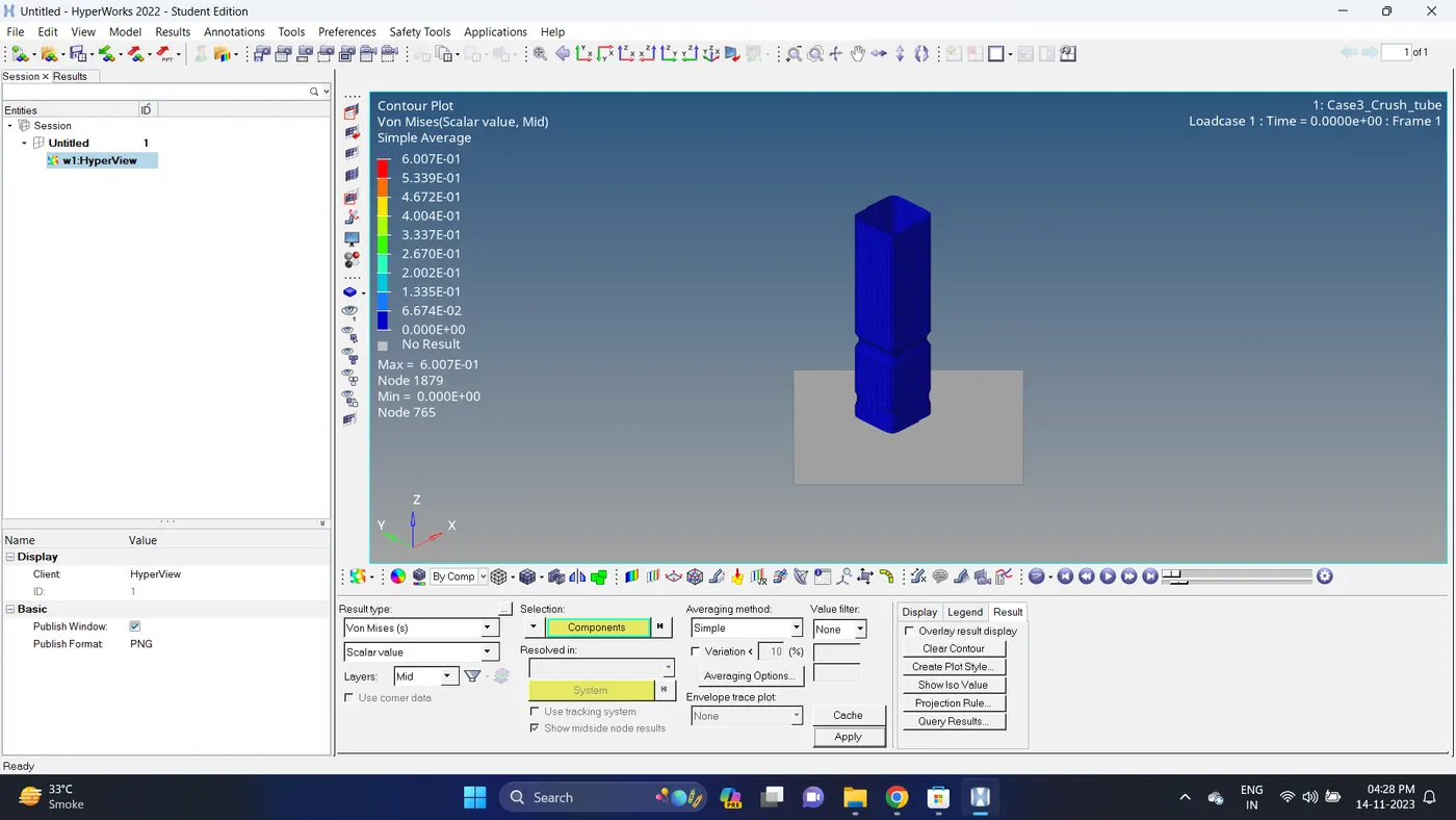
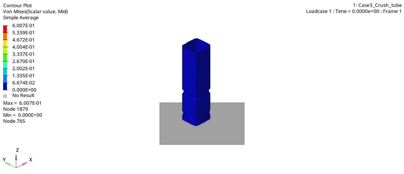
12. Go to the contour - change result type to Von mises (s), averaging method to simple, click on apply and play the animation.
Maximum stress = 0.6007 and Minimum stess is 0.
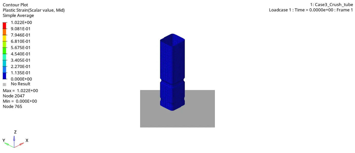
13. Similarly plot plastic strain.
Maximum strain is 1.022 and Minimum strain is 0.
Case 4:
1. Import the Case3_Crush_tube_0000.rad file.
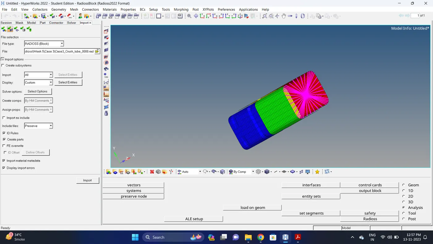
2. Remove notches using Align Node option. Go to Geom - node edit - align node.
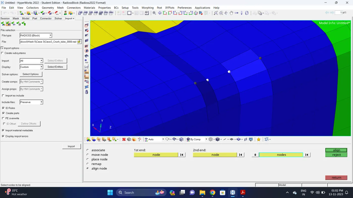
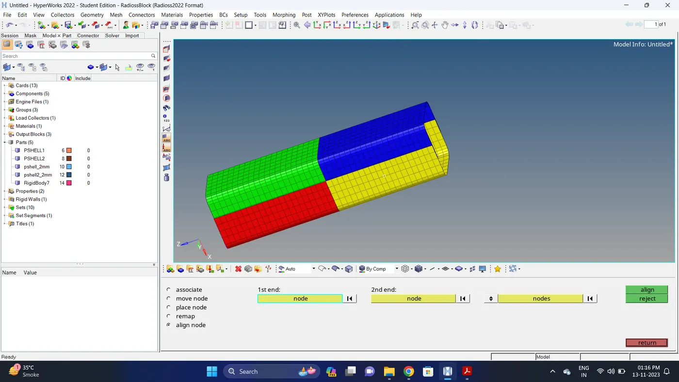
3. Remove the Boundary Conditons of rigid body.
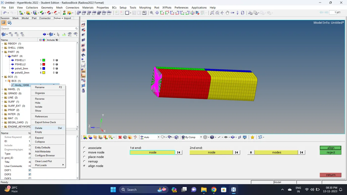
4. Run the simulation.
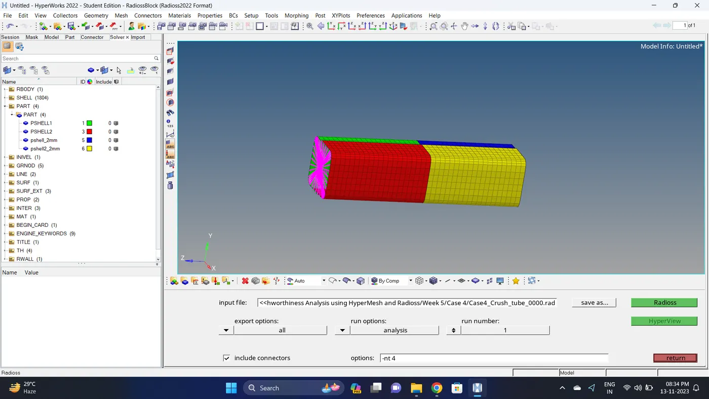
Go to Analysis - Radioss - click on save as, Rename the file to Case4_Crush_tube and at the end type .rad - Ensure that export option is set to all and Include connectors is tick - Click Radioss to run the simulation.
Note: If the stimulation is not running it taking time then copy the given input 0000.rad and 0001.rad file to folder, Rename both the file to Case4_Crush_tube, click on the 0000.rad file click save and overwrite it.
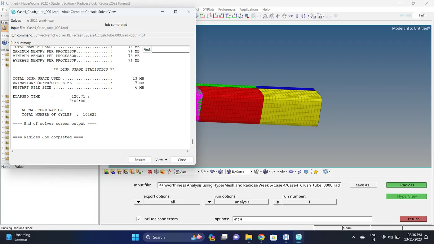
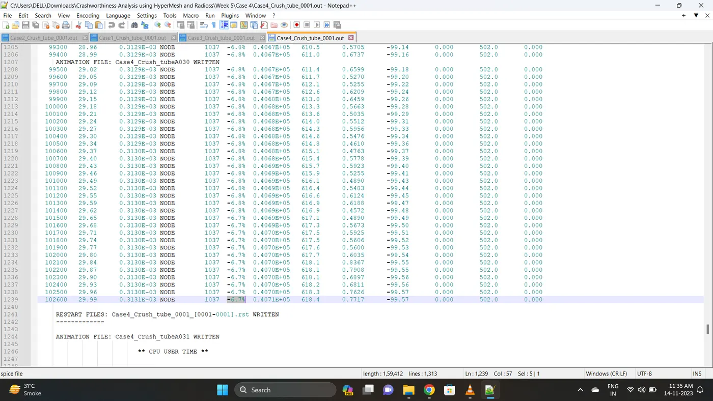
5. Open 0001.out file in notepad ++ and check the maximum total energy error and mass error.
The torelance for the energy error is -15 to +5 % and mass error is upto 2 %.
Energy error is -6.7% & Mass error is 0%.
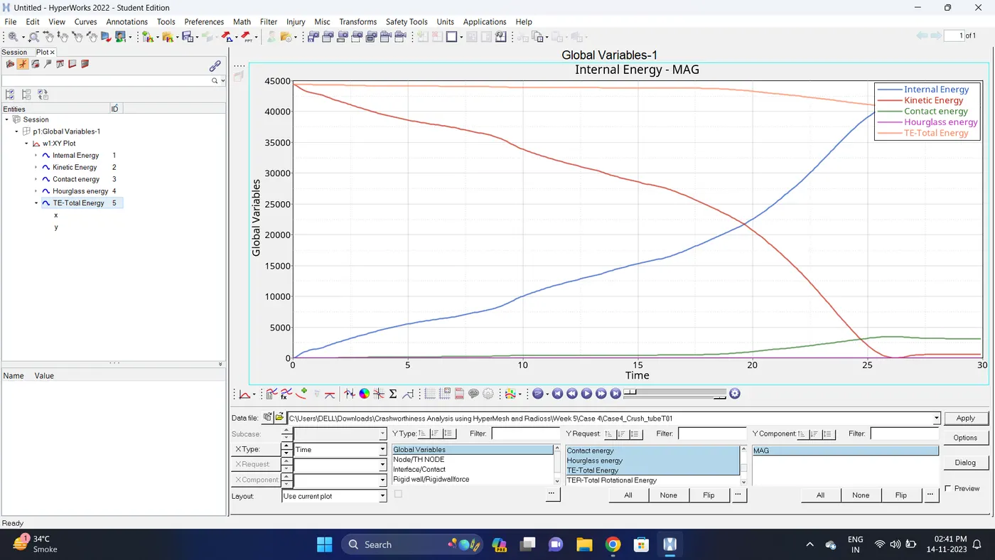
6. Open the Hyperwork in Hypergraph 2D view.
7. Open the T01 file from case_4 and select the Global Variable - Internal energy, Kinetic energy, Contact Energy, Hourglass Energy and Total Energy - Click apply to plot the graph.
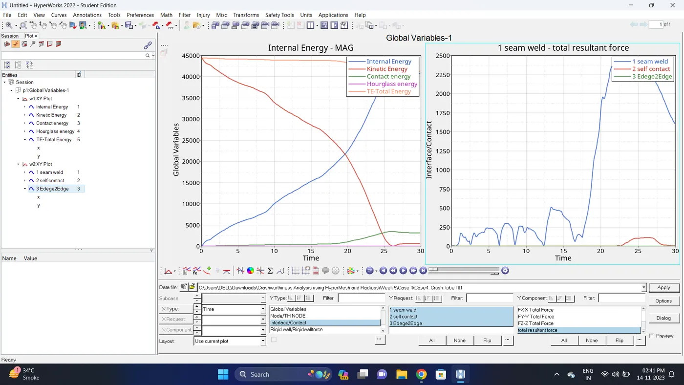
8. Change the windows page layout to 2 and in second window plot the Interface/Contact forces graph.
To plot the graph select Interface/Contact - Select all the contact types - total resultant force - click apply
9. Change the windows page layout to 3 and in Third window plot the rigid wall forces graph.
To plot graph select Rigid wall/Rwall-forces - 3 rwall - total resultant force - click apply
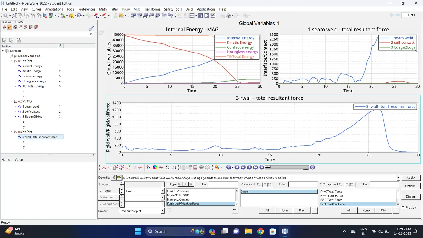
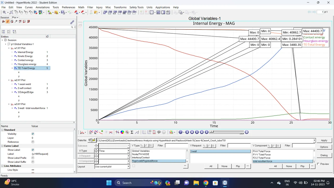
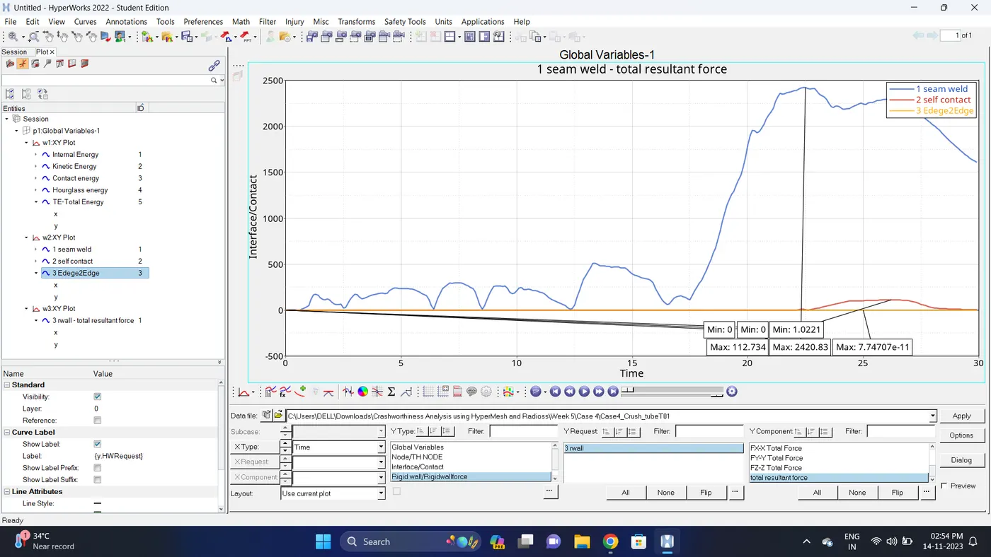
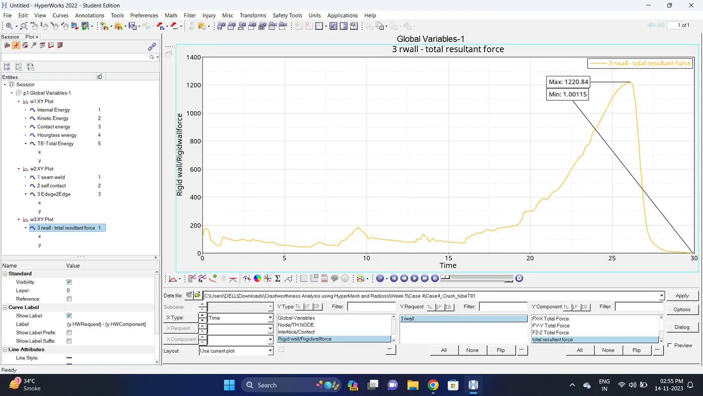
10. Note down the minimum and maximum value of various Energy by right click on any energy - Single curve math - Min Note. similarly do for maximum
Note: after getting graph reading turn off that graph and do next reading.
| Sr. no | Name | Minimum | Maximum |
| 1 | Internal energy | 0 | 40862.4 |
| 2 | Kinetic energy | 0.284101 | 44400.7 |
| 3 | Contact Energy | 0 | 3480.35 |
| 4 | Hourglass Energy | 0 | 0 |
| 5 | Total Energy | 40862.7 | 44400.7 |
| 6 | Seam Weld (Type2 Contact) | 1.0221 | 2420.83 |
| 7 | Self Contact (Type7 Contact) | 0 | 112.734 |
| 8 | Edge2Edge (Type11 Contact) | 0 | 7.74707e-11 |
| 9 | Rigid Wall Forces (Total Resultant Force) | 1.00115 | 1220.84 |
11. Import the .h3d file.
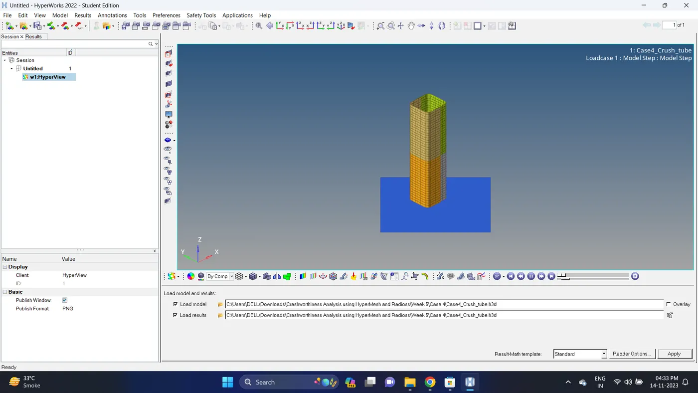
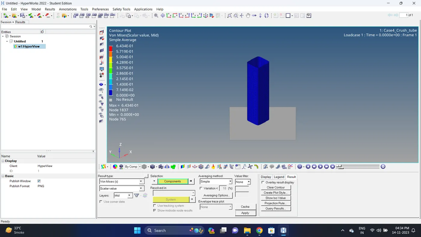
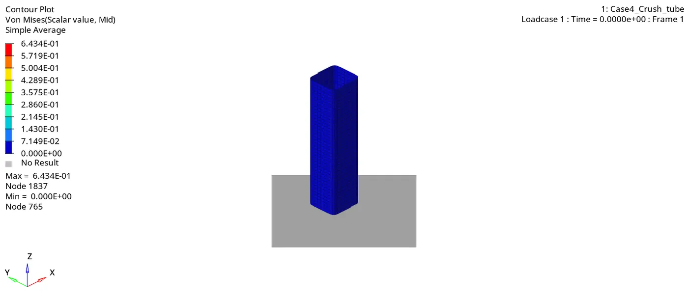
12. Go to the contour - change result type to Von mises (s), averaging method to simple, click on apply and play the animation.
Maximum stress = 0.6434 and Minimum stess is 0.
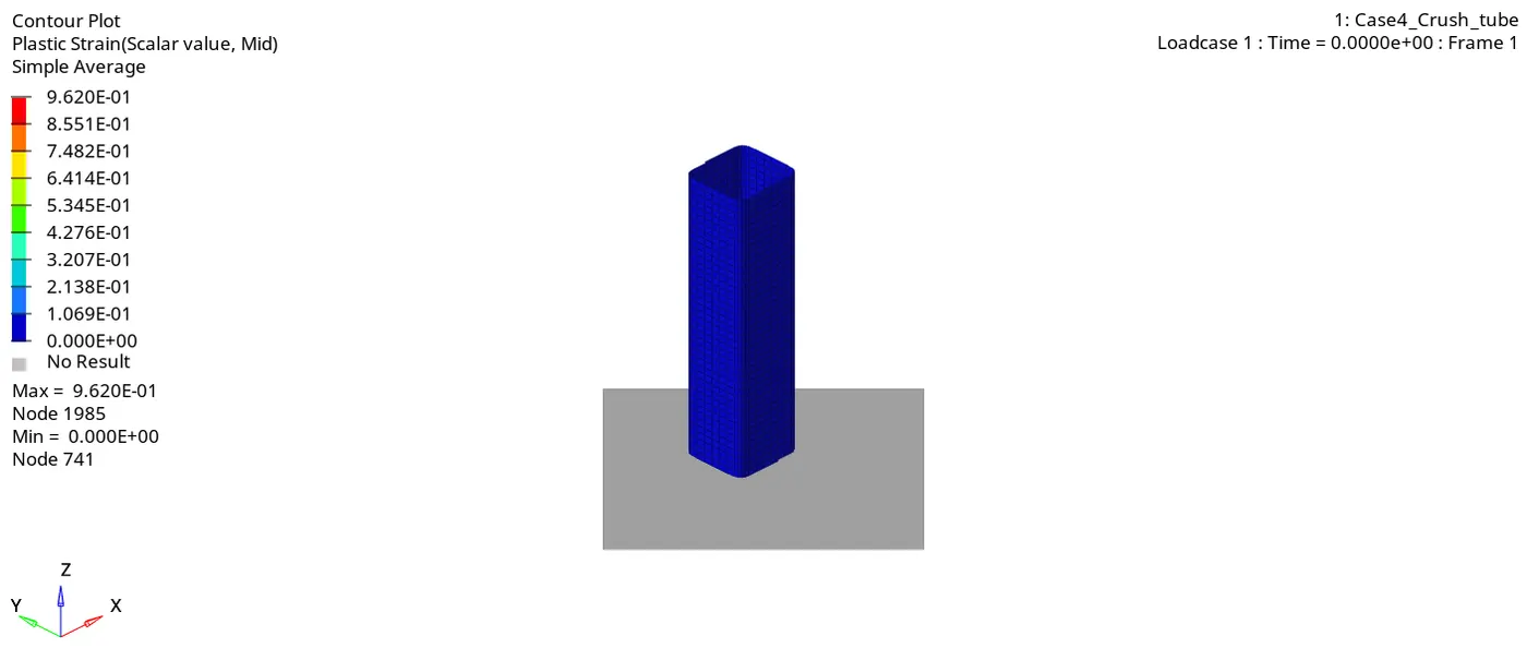
13. Similarly plot plastic strain.
Maximum strain is 0.962 and Minimum strain is 0.
Case 5:
1. Import the Case4_Crush_tube_0000.rad file.
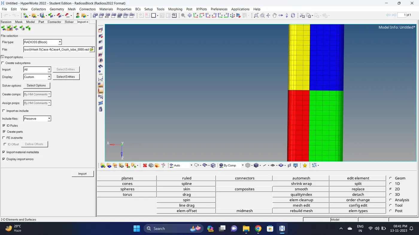
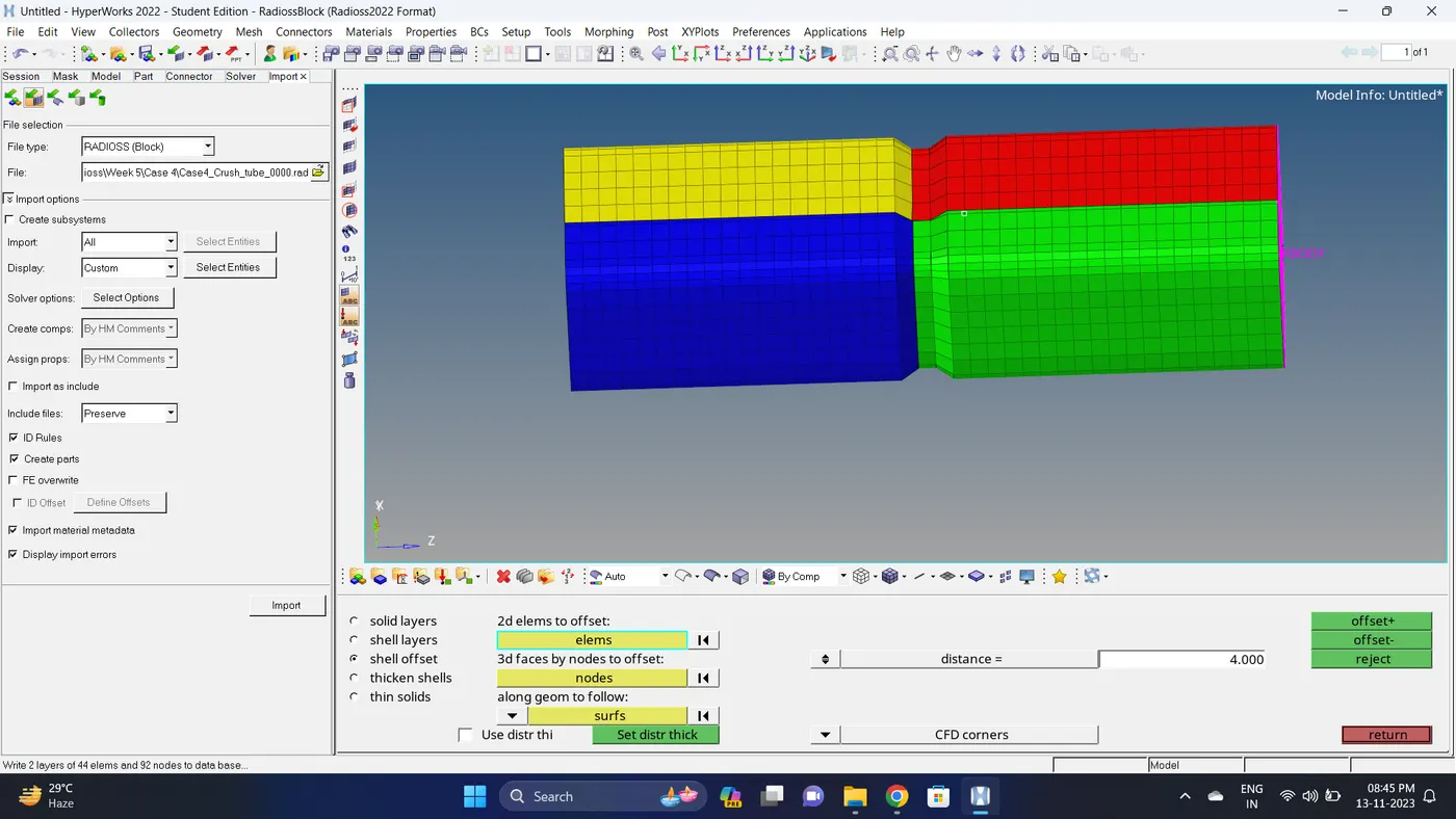
2. Create a new notch in the middle. Go to 2D - elem offset - shell offset - select element - give distance value - click offset.
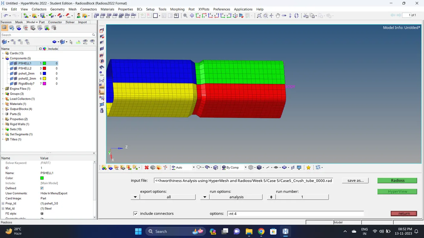
3. Run the simulation.
Go to Analysis - Radioss - click on save as, Rename the file to Case5_Crush_tube and at the end type .rad - Ensure that export option is set to all and Include connectors is tick - Click Radioss to run the simulation.
Note: If the stimulation is not running it taking time then copy the given input 0000.rad and 0001.rad file to folder, Rename both the file to Case5_Crush_tube, click on the 0000.rad file click save and overwrite it.
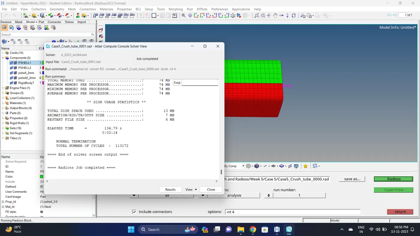
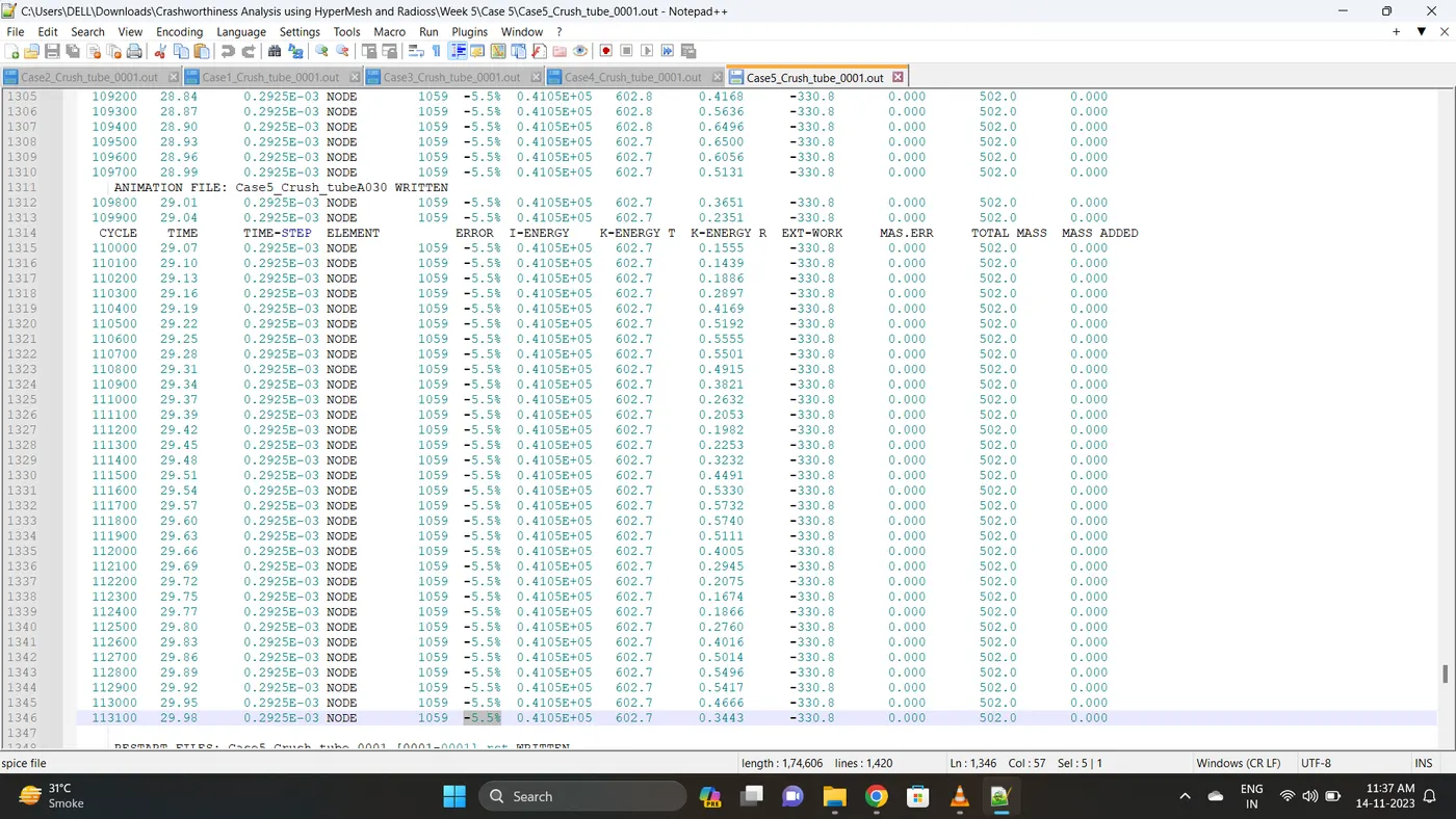
4. Open 0001.out file in notepad ++ and check the maximum total energy error and mass error.
The torelance for the energy error is -15 to +5 % and mass error is upto 2 %.
Energy error is -5.5% & Mass error is 0%.
5. Open the Hyperwork in Hypergraph 2D view.
6. Open the T01 file from case_5 and select the Global Variable - Internal energy, Kinetic energy, Contact Energy, Hourglass Energy and Total Energy - Click apply to plot the graph.
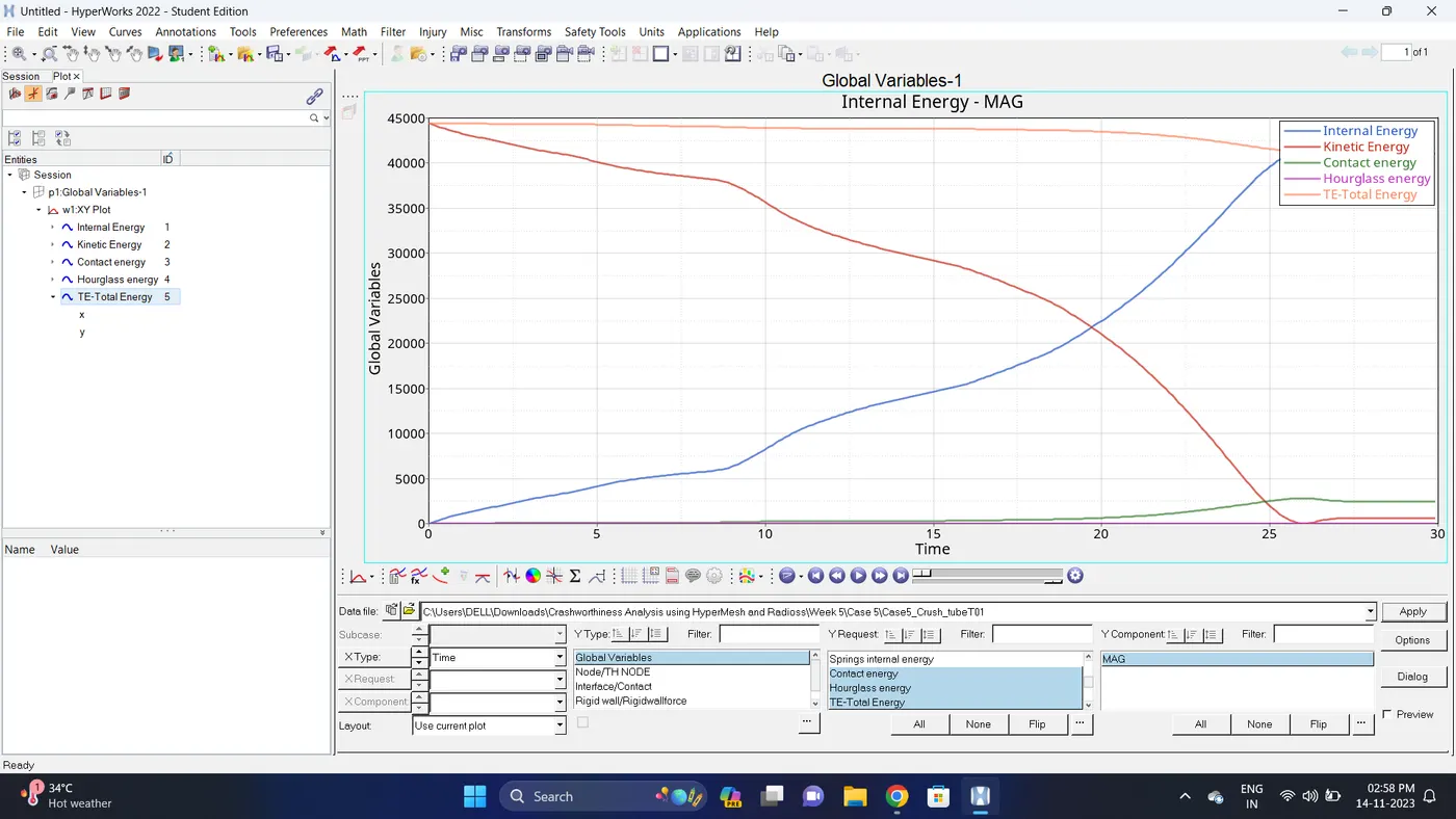
7. Change the windows page layout to 2 and in second window plot the Interface/Contact forces graph.
To plot the graph select Interface/Contact - Select all the contact types - total resultant force - click apply.

8. Change the windows page layout to 3 and in Third window plot the rigid wall forces graph.
To plot graph select Rigid wall/Rwall-forces - 3 rwall - total resultant force - click apply.
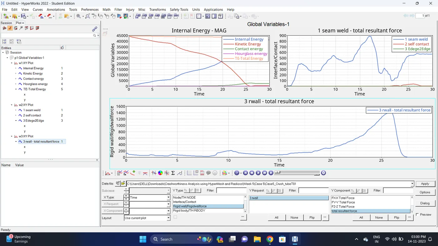
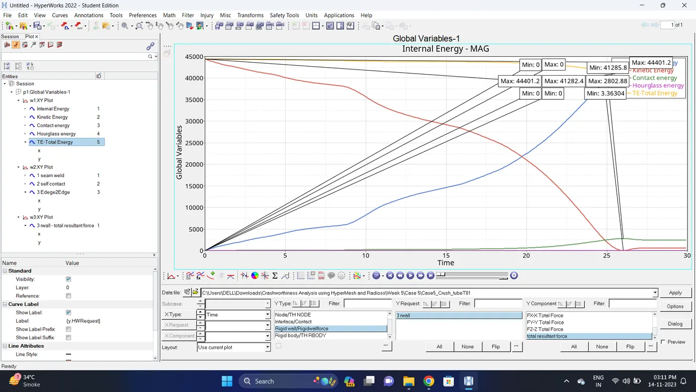
9. Note down the minimum and maximum value of various Energy by right click on any energy - Single curve math - Min Note. similarly do for maximum.
Note: after getting graph reading turn off that graph and do next reading.
| Sr. no | Name | Minimum | Maximum |
| 1 | Internal energy | 0 | 41282.4 |
| 2 | Kinetic energy | 3.36304 | 44401.2 |
| 3 | Contact Energy | 0 | 2802.88 |
| 4 | Hourglass Energy | 0 | 0 |
| 5 | Total Energy | 41285.8 | 44401.2 |
| 6 | Seam Weld (Type2 Contact) | 1.00762 | 887.787 |
| 7 | Self Contact (Type7 Contact) | 0 | 38.8271 |
| 8 | Edge2Edge (Type11 Contact) | 0 | 6.90518e-11 |
| 9 | Rigid Wall Forces (Total Resultant Force) | 0 | 1415.43 |
10. Import the .h3d file.
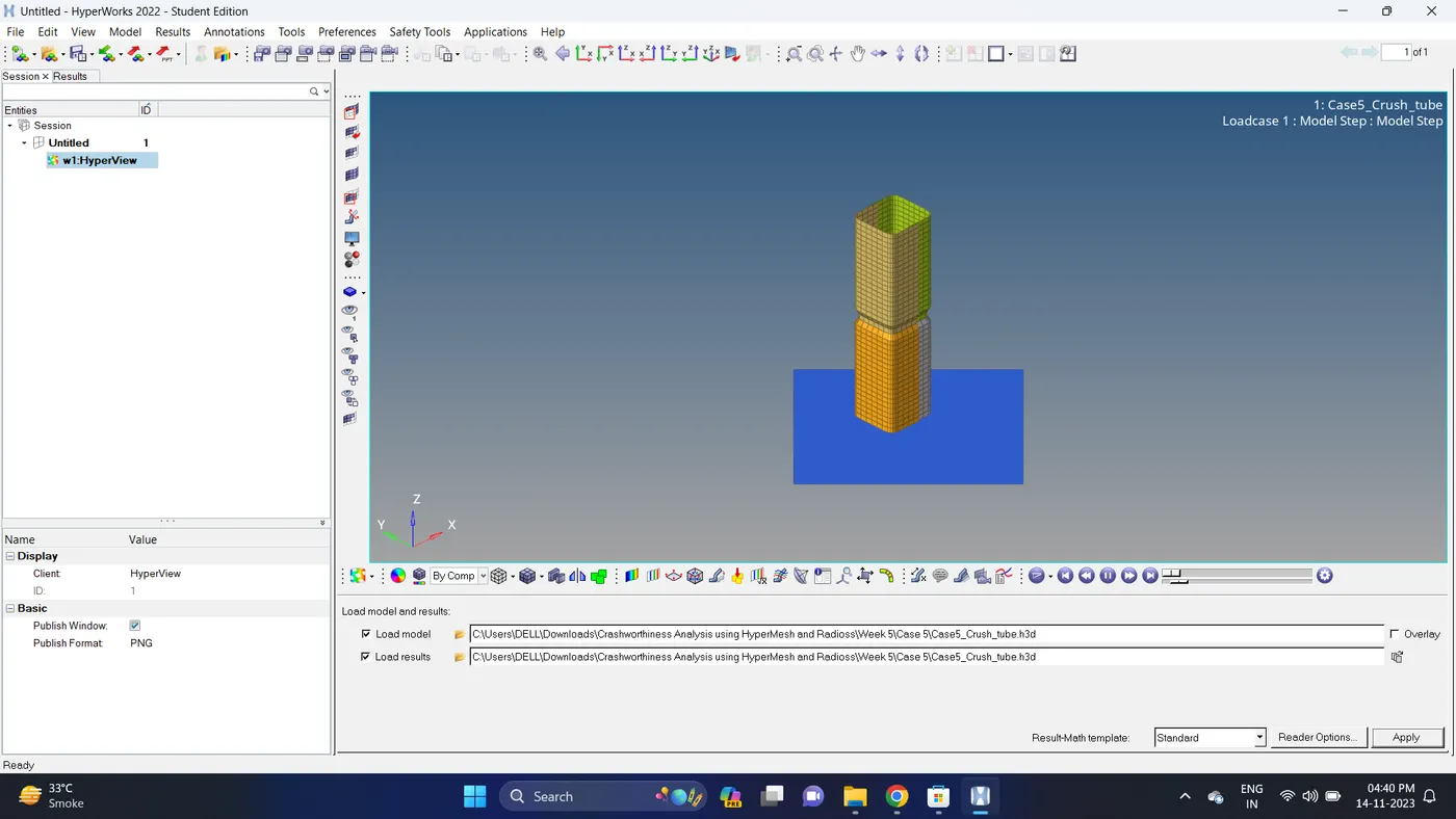
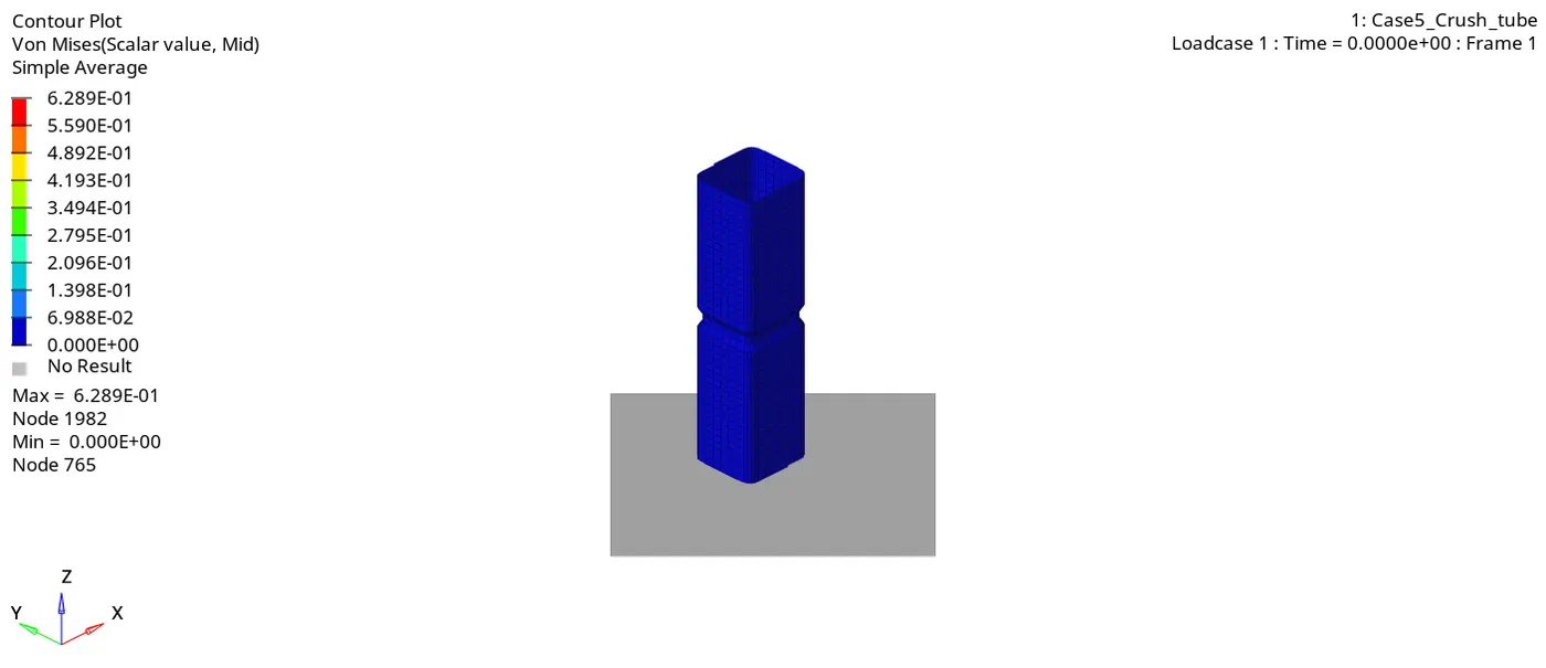
11. Go to the contour - change result type to Von mises (s), averaging method to simple, click on apply and play the animation.
Maximum stress = 0.6289 and Minimum stess is 0.
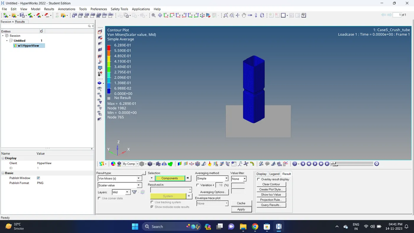
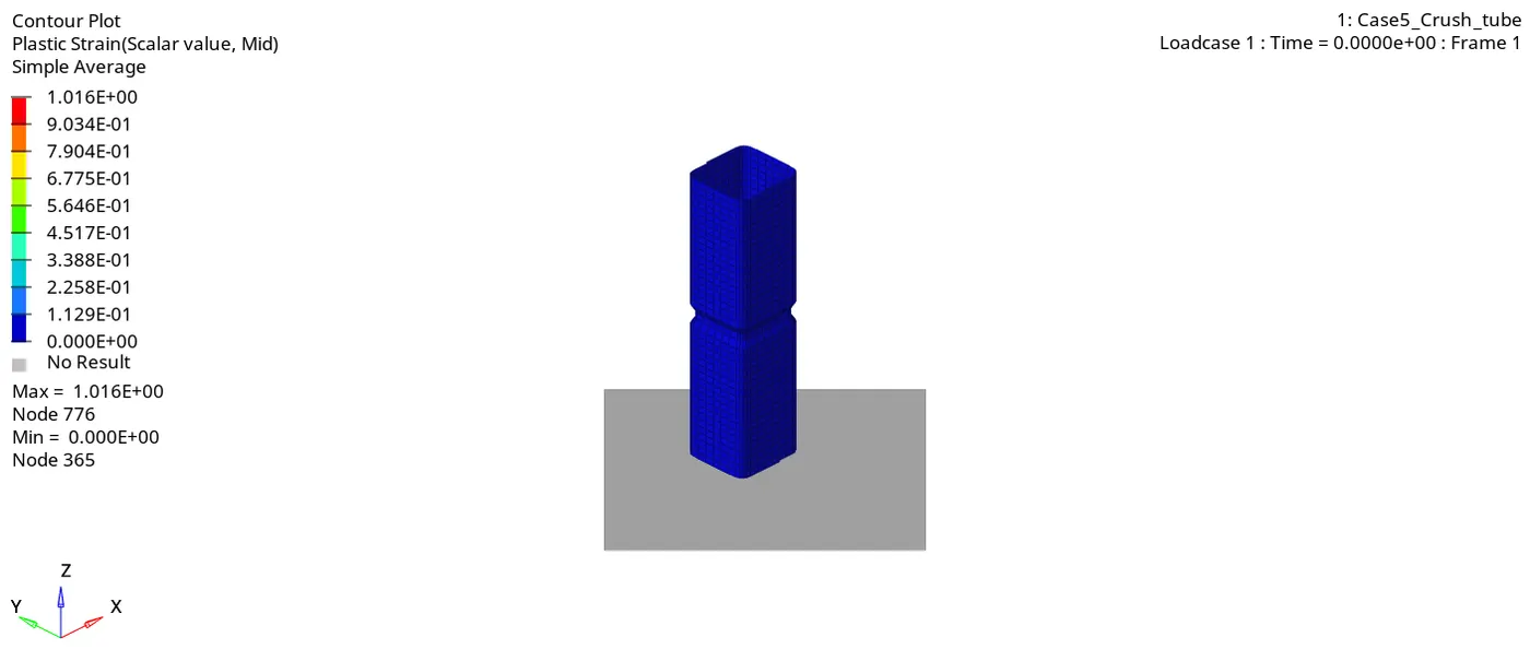
12. Similarly plot plastic strain.
Maximum strain is 1.016 and Minimum strain is 0.
Case 6
1. Import the Case4_Crush_tube_0000.rad file.
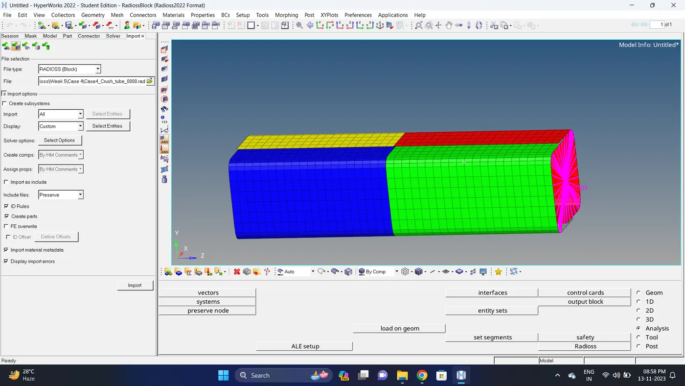
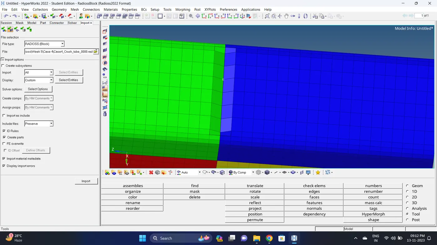
2. Create a new notch on opposite face. Go to 2D - elem offset - shell offset - select element - give distance value - click offset.
3. Run the simulation.
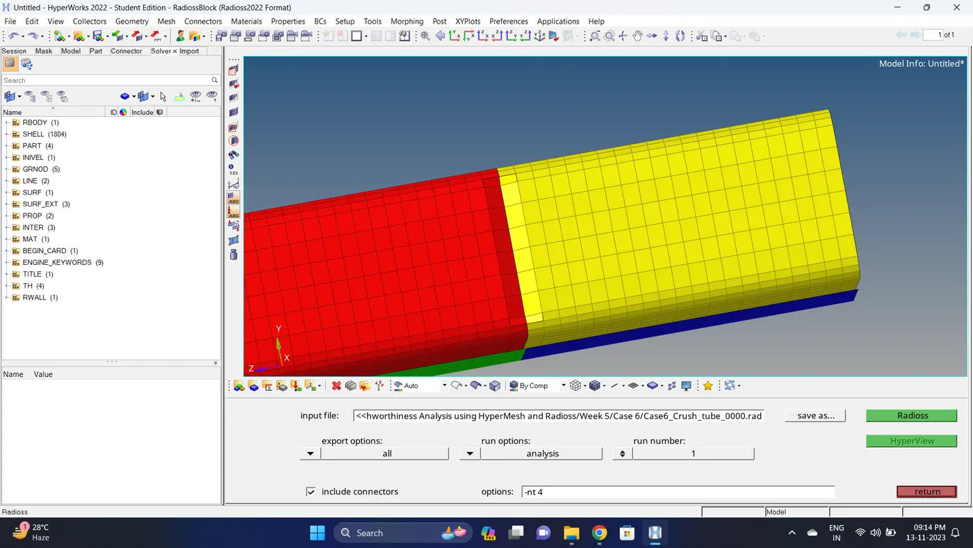
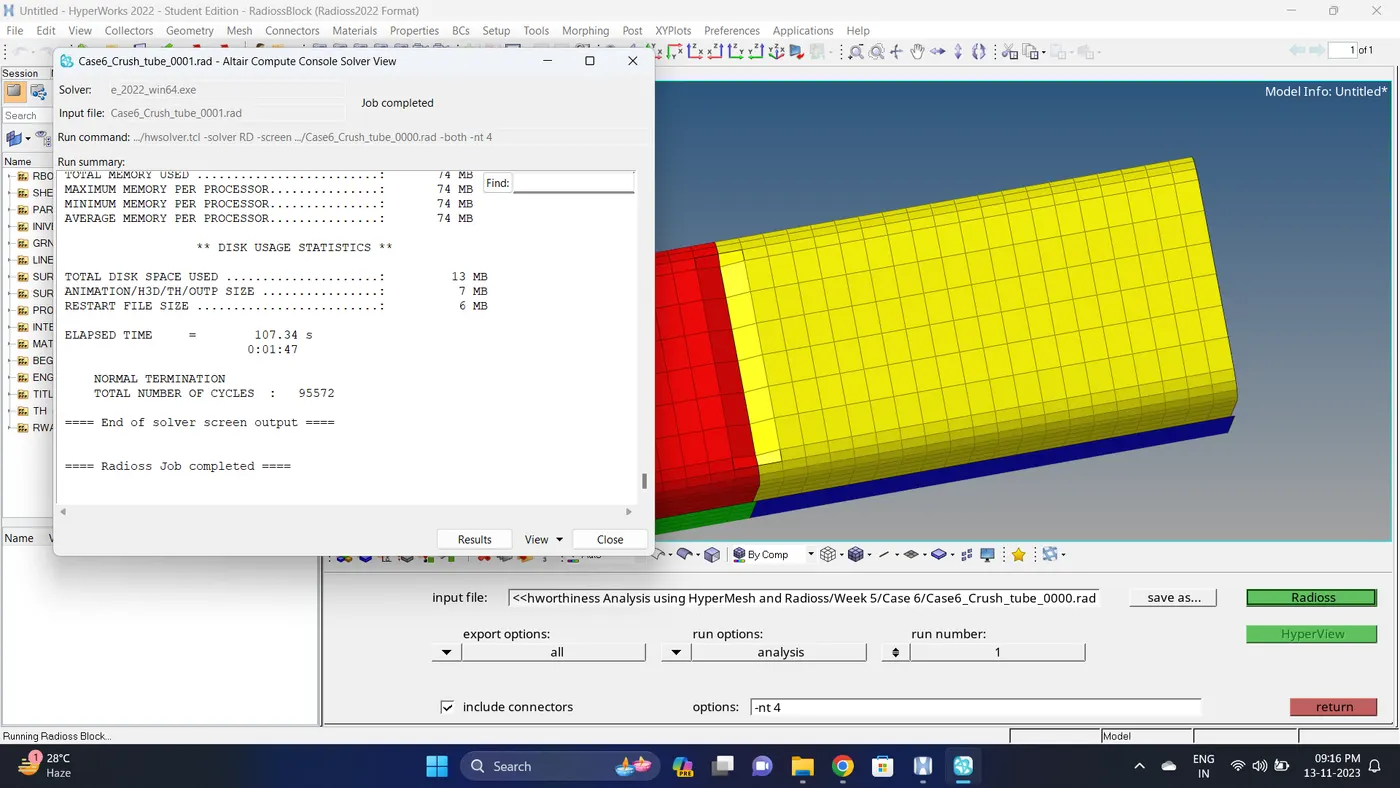
Go to Analysis - Radioss - click on save as, Rename the file to Case6_Crush_tube and at the end type .rad - Ensure that export option is set to all and Include connectors is tick - Click Radioss to run the simulation.
Note: If the stimulation is not running it taking time then copy the given input 0000.rad and 0001.rad file to folder, Rename both the file to Case6_Crush_tube, click on the 0000.rad file click save and overwrite it.
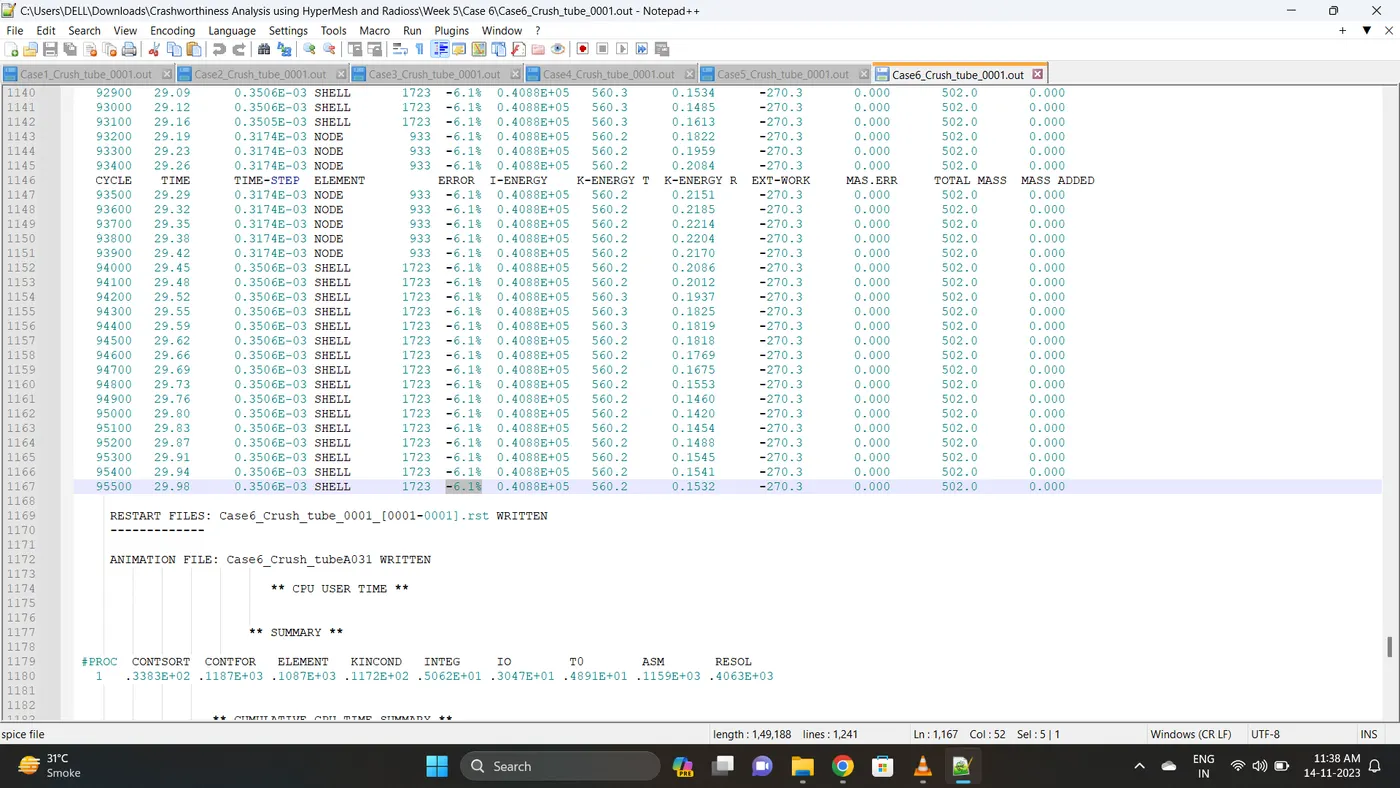
4. Open 0001.out file in notepad ++ and check the maximum total energy error and mass error.
The torelance for the energy error is -15 to +5 % and mass error is upto 2 %.
Energy error is -6.1% & Mass error is 0%.
5. Open the Hyperwork in Hypergraph 2D view.
6. Open the T01 file from case_6 and select the Global Variable - Internal energy, Kinetic energy, Contact Energy, Hourglass Energy and Total Energy - Click apply to plot the graph.
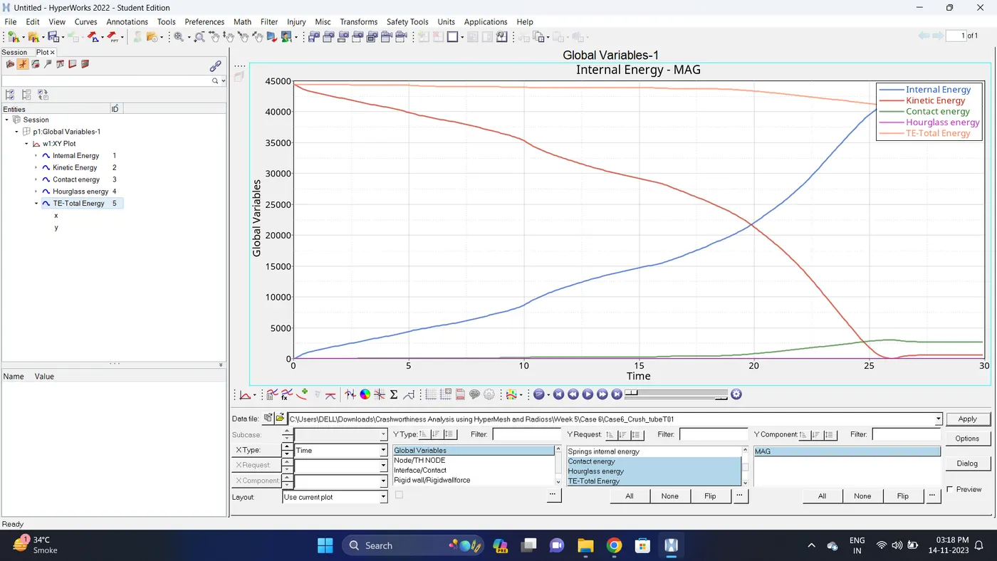
7. Change the windows page layout to 2 and in second window plot the Interface/Contact forces graph.
To plot the graph select Interface/Contact - Select all the contact types - total resultant force - click apply.
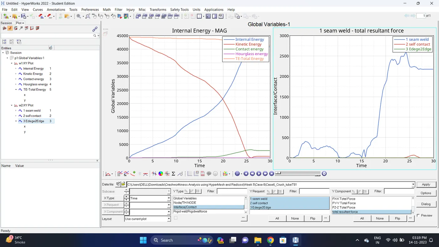
8. Change the windows page layout to 3 and in Third window plot the rigid wall forces graph.
To plot graph select Rigid wall/Rwall-forces - 3 rwall - total resultant force - click apply.
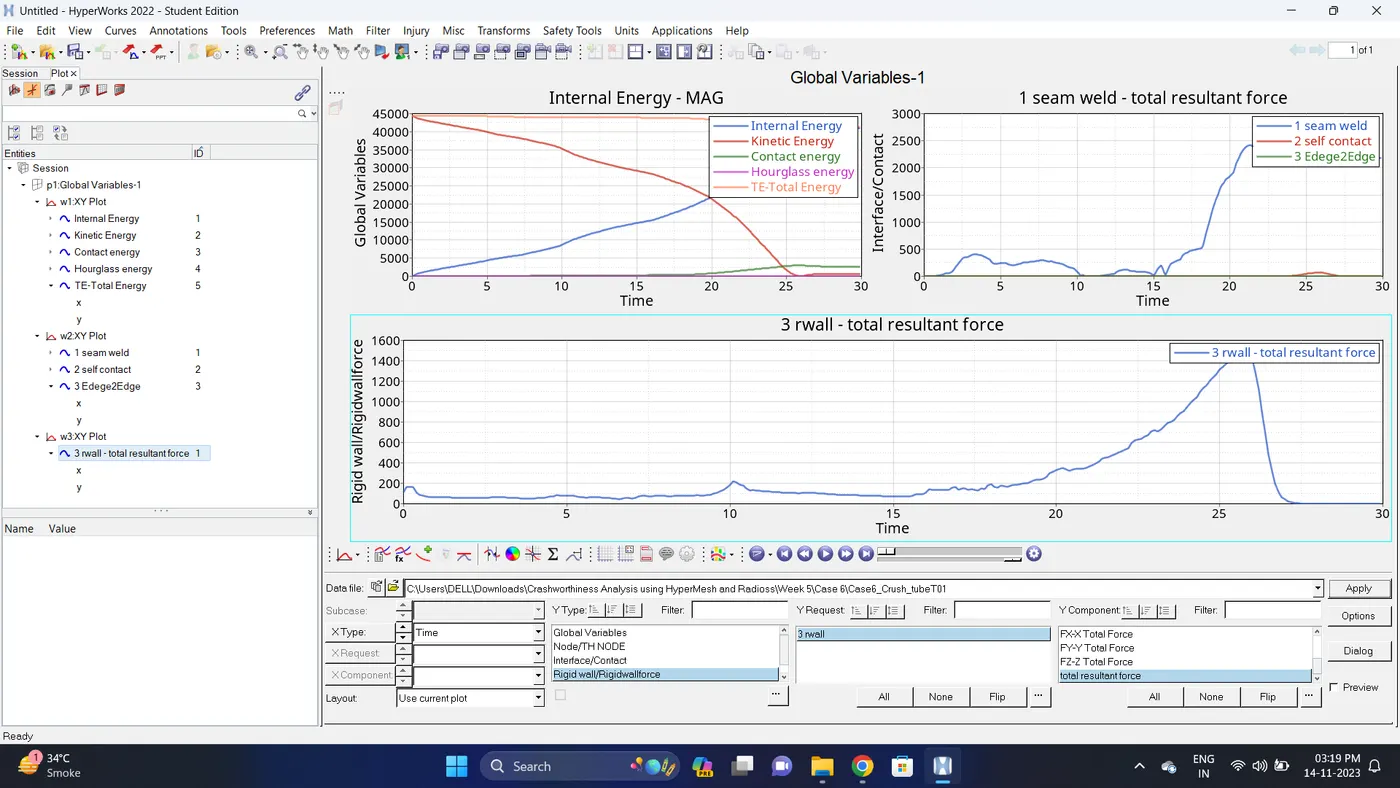
9. Note down the minimum and maximum value of various Energy by right click on any energy - Single curve math - Min Note. similarly do for maximum
Note: after getting graph reading turn off that graph and do next reading.
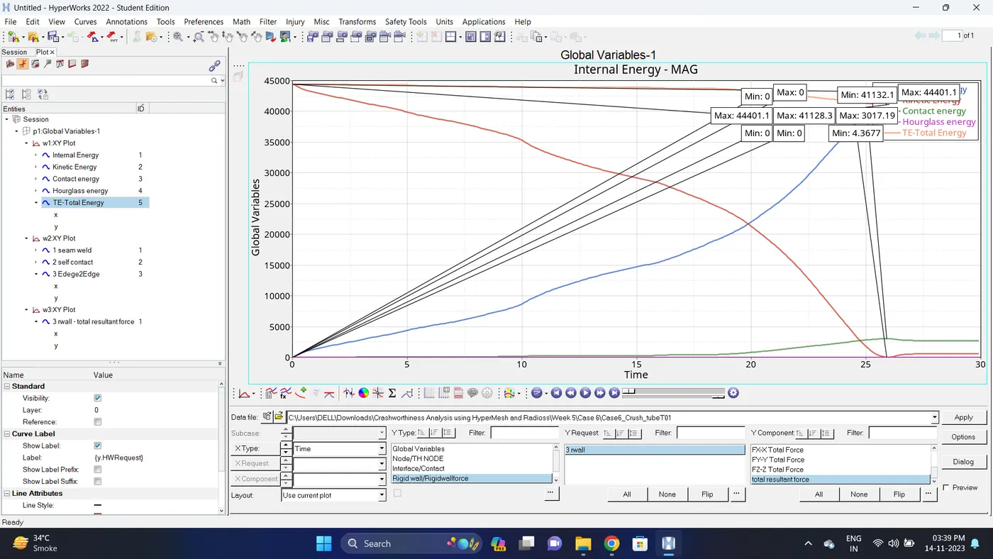
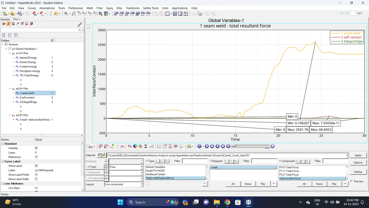
| Sr. no | Name | Minimum | Maximum |
| 1 | Internal energy | 0 | 41128.3 |
| 2 | Kinetic energy | 4.3677 | 44401.1 |
| 3 | Contact Energy | 0 | 3017.19 |
| 4 | Hourglass Energy | 0 | 0 |
| 5 | Total Energy | 41132.1 | 44401.1 |
| 6 | Seam Weld (Type2 Contact) | 0.106207 | 2591.79 |
| 7 | Self Contact (Type7 Contact) | 0 | 66.6923 |
| 8 | Edge2Edge (Type11 Contact) | 0 | 7.55556e-11 |
| 9 | Rigid Wall Forces (Total Resultant Force) | 0 | 1461.75 |
10. Import the .h3d file.
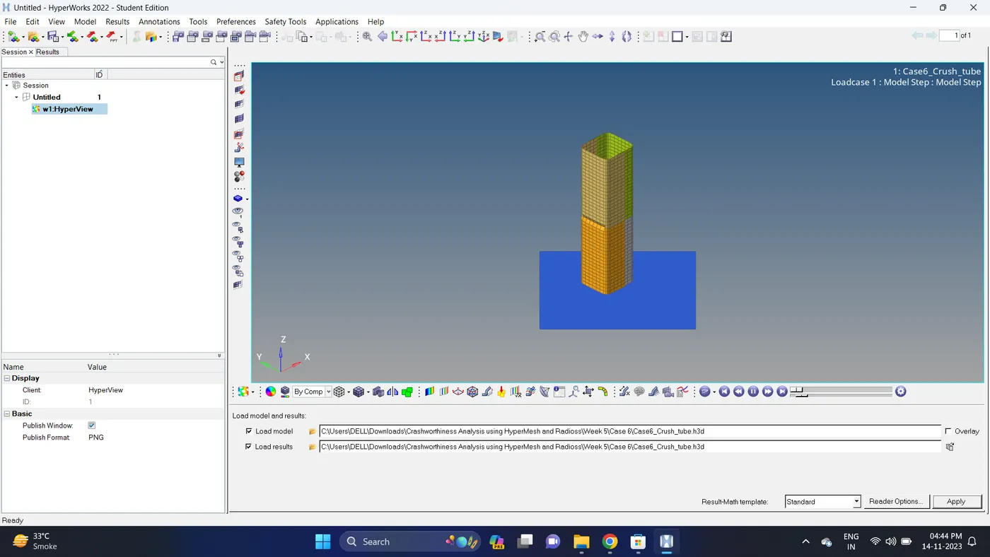
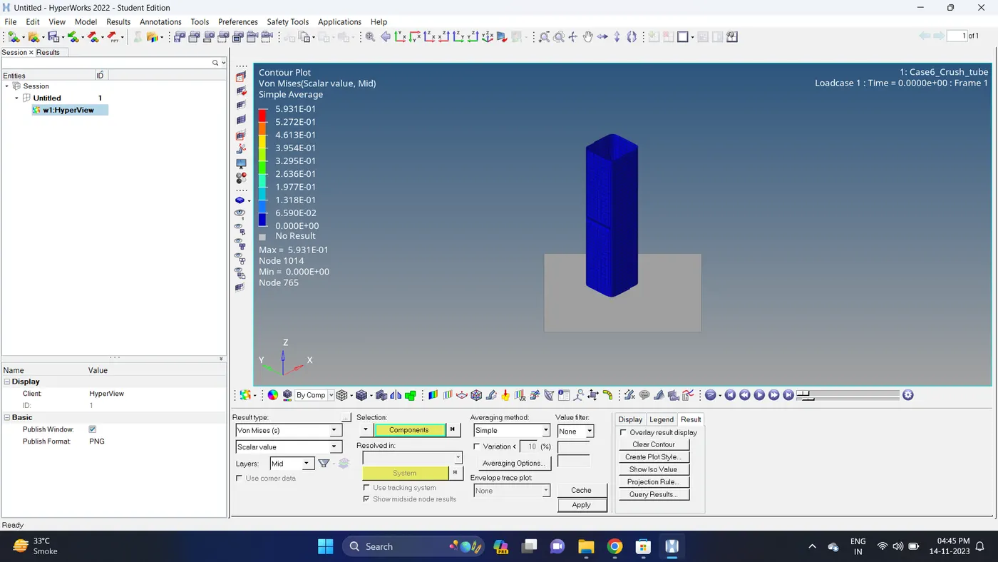
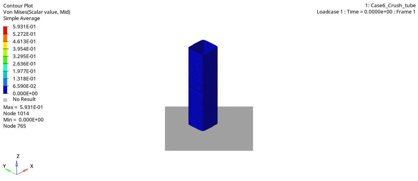
11. Go to the contour - change result type to Von mises (s), averaging method to simple, click on apply and play the animation.
Maximum stress = 0.5931 and Minimum stess is 0.
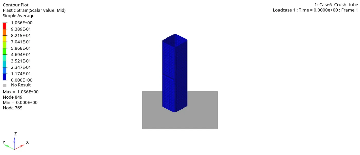
12. Similarly plot plastic strain.
Maximum strain is 1.056 and Minimum strain is 0.
Result:
Case 1:
| Sr. no | Name | Minimum | Maximum |
| 1 | Internal energy | 0 | 42273 |
| 2 | Kinetic energy | 1.59545 | 44400.8 |
| 3 | Contact Energy | 0 | 2029.77 |
| 4 | Hourglass Energy | 0 | 0 |
| 5 | Total Energy | 42274.4 | 44400.8 |
| 6 | Seam Weld (Type2 Contact) Total Resultant Force | 0.197936 | 33.1513 |
| 7 | Self Contact (Type7 Contact) Total Resultant Force | 0 | 1057.05 |
| 8 | Rigid Wall Forces (Total Resultant Force) | 0 | 1338.18 |
| 9 | Energy Error | -0% | -4.6% |
| 10 | Mass Error | 0% | 0% |
| 11 | Von Mises Stress | 0 | 0.6953 |
| 12 | Plastic Strain | 0 | 1.192 |
Case 2:
| Sr. no | Name | Minimum | Maximum |
| 1 | Internal energy | 0 | 42273 |
| 2 | Kinetic energy | 1.59545 | 44400.8 |
| 3 | Contact Energy | 0 | 2029.77 |
| 4 | Hourglass Energy | 0 | 0 |
| 5 | Total Energy | 42274.4 | 44400.8 |
| 6 | Seam Weld (Type2 Contact) Total Resultant Force | 0.197936 | 33.1513 |
| 7 | Self Contact (Type7 Contact) Total Resultant Force | 0 | 1057.05 |
| 8 | Rigid Wall Forces (Total Resultant Force) | 0 | 1338.18 |
| 9 | Energy Error | -0% | -4.6% |
| 10 | Mass Error | 0% | 0% |
| 11 | Von Mises Stress | 0 | 0.6953 |
| 12 | Plastic Strain | 0 | 1.192 |
Case 3:
| Sr. no | Name | Minimum | Maximum |
| 1 | Internal energy | 0 | 41311 |
| 2 | Kinetic energy | 0.391428 | 44400.8 |
| 3 | Contact Energy | 0 | 3045.2 |
| 4 | Hourglass Energy | 0 | 0 |
| 5 | Total Energy | 41311.4 | 44400.8 |
| 6 | Seam Weld (Type2 Contact) | 1.07452 | 1302.54 |
| 7 | Self Contact (Type7 Contact) | 0 | 0 |
| 8 | Edge2Edge (Type11 Contact) | 1.96651e-14 | 4.18542e-11 |
| 9 | Rigid Wall Forces (Total Resultant Force) | 0 | 1542.27 |
| 10 | Energy Error | -0% | -6.7% |
| 11 | Mass Error | 0% | 0% |
| 12 | Von Mises Stress | 0 | 0.6007 |
| 13 | Plastic Strain | 0 | 1.022 |
Case 4:
| Sr. no | Name | Minimum | Maximum |
| 1 | Internal energy | 0 | 40862.4 |
| 2 | Kinetic energy | 0.284101 | 44400.7 |
| 3 | Contact Energy | 0 | 3480.35 |
| 4 | Hourglass Energy | 0 | 0 |
| 5 | Total Energy | 40862.7 | 44400.7 |
| 6 | Seam Weld (Type2 Contact) | 1.0221 | 2420.83 |
| 7 | Self Contact (Type7 Contact) | 0 | 112.734 |
| 8 | Edge2Edge (Type11 Contact) | 0 | 7.74707e-11 |
| 9 | Rigid Wall Forces (Total Resultant Force) | 1.00115 | 1220.84 |
| 10 | Energy Error | -0% | -7.8% |
| 11 | Mass Error | 0% | 0% |
| 12 | Von Mises Stress | 0 | 0.6434 |
| 13 | Plastic Strain | 0 | 0.962 |
Case 5:
| Sr. no | Name | Minimum | Maximum |
| 1 | Internal energy | 0 | 41282.4 |
| 2 | Kinetic energy | 3.36304 | 44401.2 |
| 3 | Contact Energy | 0 | 2802.88 |
| 4 | Hourglass Energy | 0 | 0 |
| 5 | Total Energy | 41285.8 | 44401.2 |
| 6 | Seam Weld (Type2 Contact) | 1.00762 | 887.787 |
| 7 | Self Contact (Type7 Contact) | 0 | 38.8271 |
| 8 | Edge2Edge (Type11 Contact) | 0 | 6.90518e-11 |
| 9 | Rigid Wall Forces (Total Resultant Force) | 0 | 1415.43 |
| 10 | Energy Error | -0% | -6.3% |
| 11 | Mass Error | 0% | 0% |
| 12 | Von Mises Stress | 0 | 0.6289 |
| 13 | Plastic Strain | 0 | 1.016 |
Case 6:
| Sr. no | Name | Minimum | Maximum |
| 1 | Internal energy | 0 | 41128.3 |
| 2 | Kinetic energy | 4.3677 | 44401.1 |
| 3 | Contact Energy | 0 | 3017.19 |
| 4 | Hourglass Energy | 0 | 0 |
| 5 | Total Energy | 41132.1 | 44401.1 |
| 6 | Seam Weld (Type2 Contact) | 0.106207 | 2591.79 |
| 7 | Self Contact (Type7 Contact) | 0 | 66.6923 |
| 8 | Edge2Edge (Type11 Contact) | 0 | 7.55556e-11 |
| 9 | Rigid Wall Forces (Total Resultant Force) | 0 | 1461.75 |
| 10 | Energy Error | 0% |
-6.8 |
| 11 | Mass Error | 0% | 0% |
| 12 | Von Mises Stress | 0 | 0.5931 |
| 13 | Plastic Strain | 0 | 1.056 |
- In case 1 the PLAS_JOHNS material card has been used and TYPE2 and TYPE7 Contact has been used.
- In case 2 the only change was in TYPE7 Contact interface. In TYPE7 we only change INACTIV = 0 to 6 (Gap is variable with time but initial penetration is computed).
- As we can see in the table above there are no changes in energy and forces in case 1 and case 2.
- In case 3 new TYPE 11 contact has been created. In case of Edge crossing, TYPE11 contact is used to capture a physics Correctly.
- As we can see that why there are changes in Internal energy, Kinetic energy, Contact energy, All Contact/Interface forces, Enregy error, Mass error, Von Mises stress and Plastic Strain in above table.
- In case 4 all the Notches are removed due to this Internal energy has been droped and there are changes in Kinetic energy, Contact energy, All Contact/Interface forces, Enregy error, Mass error, Von Mises stress and Plastic Strain in above table.
- In case 5 Notches are created in midddle section of model and as we can see due to notches internal energy has been increased and there are changes in other Kinetic energy, Contact energy, All Contact/Interface forces, Enregy error, Mass error, Von Mises stress and Plastic Strain in above table.
- In case 6 Middle notch has been removed and a notch only on opposite faces are created as we can see compare from case 5 internal energy are slightly decreased are there are changes in Kinetic energy, Contact energy, All Contact/Interface forces, Enregy error, Mass error, Von Mises stress and Plastic Strain in above table.
- In final we can say that when there are notches in the model Internal energy increases. The more notches are present more the internal energy and vise versa.
Conclusion:
- I learned that if in model if there are notches are present then there will be more internal energy.
- TYPE 11 contact is used for in the case of Edges crossing to capture the physics correctly.