Assignment 5-RADIOSS Interfaces & Study of Effect of Notches Challenge
Objective :
- In this question there are 6 cases are given. In each case there are some changes to be made.
- For each case run the simulation and compare the results.
- Compare for internal energy, contact energy differences.
- Observe what is the effect of notch on the results and simultions.
- Also, there is part for meshing, mesh the given part with mesh size 6.
Procedure :
Case_1 :
- Base model of crush tube is given in question.
- Import the same and perform the simulation without making any changes to it.
Case_2 :
- Again import base file ( crush_tube_0000.rad file ).
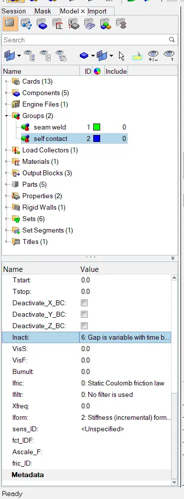
- Go to model browser --> Groups --> self contact ( contact type 7) .
- Change Inacti = 6 and perform the simulation again.
Case_3 :
- Import the base file again.
- Create type 11 contact which is a edge to edge contact.
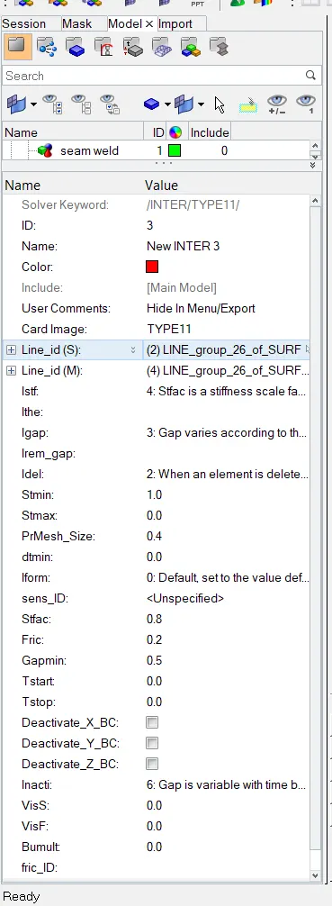
- This is the card for type 11 contact.
Case_4 :
- Import base file in radioss.
- In case no 4, remove notches from the part and boundary conditions as well.
- Boundary conditions are degree of freedoms of model. To find them go to solver browser --> boundary conditions (BCS).
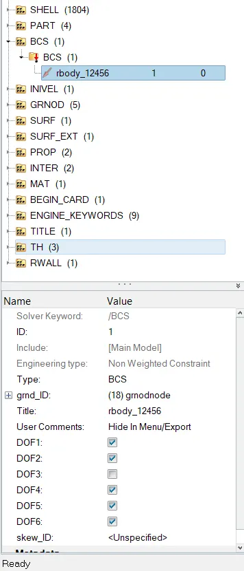
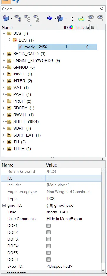
Applied BCS Removed BCS
- In first image we can see that DOF are restricted in translational X and Y and rotational X,Y, Z directions. Part is only free to move in Z translational axis.
- But, in second case, all DOF's are removed i.e., the part is free to move in any direction and axis.
- Also the notches have been removed from the model.
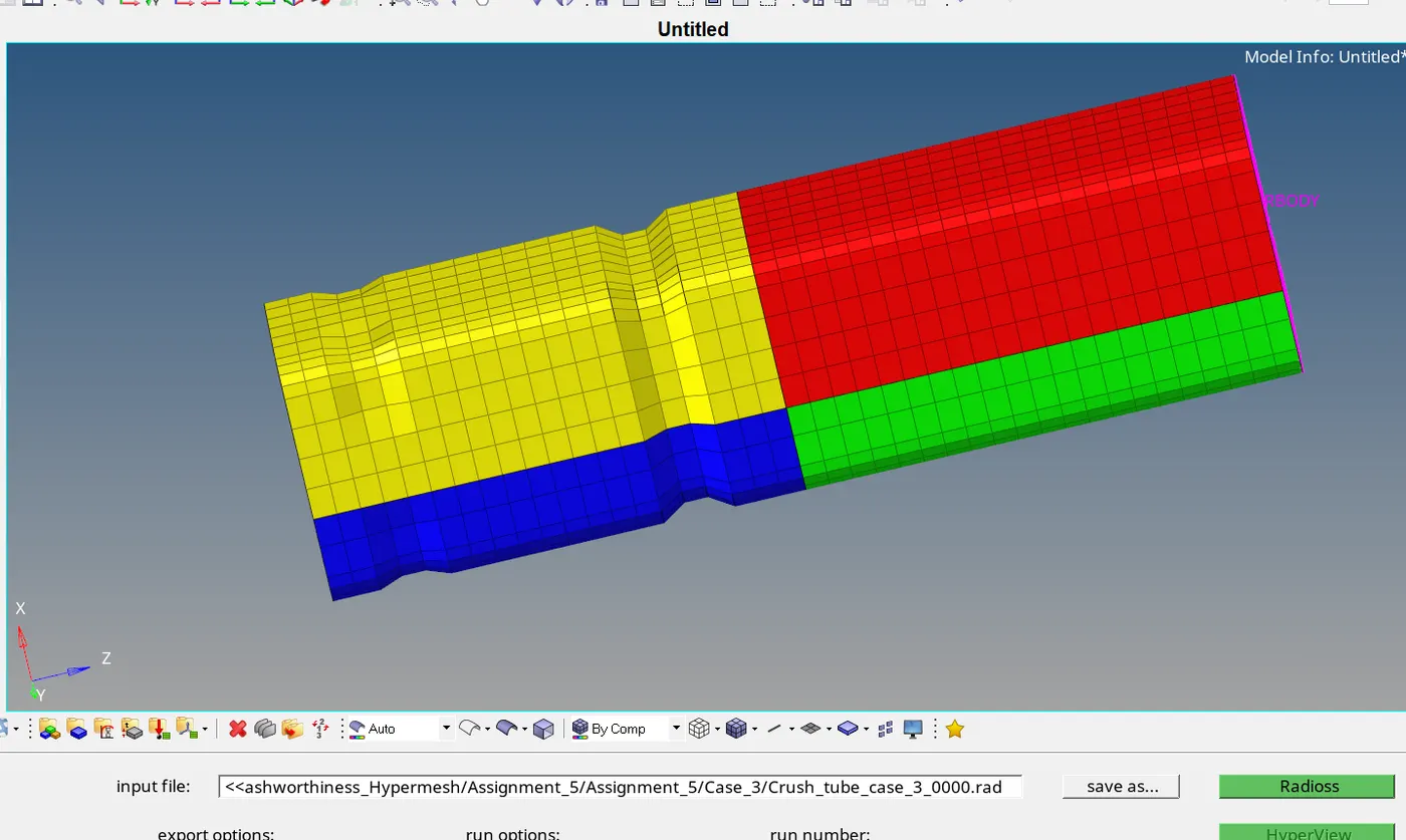
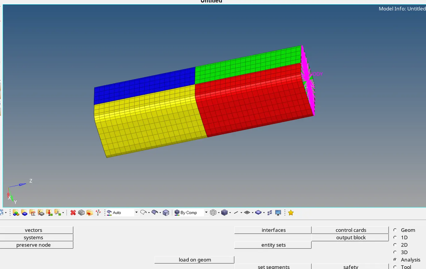
Crush tube with notches Crush tube without notch
- From above image we can see that notches have been removed from model.
Case_5 :
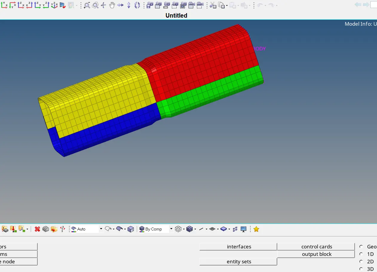
- Now, in case_5 create notch in the middle section again and run the simulation.
- This is to study that how the model will behave with only one notch.
Case_6 :
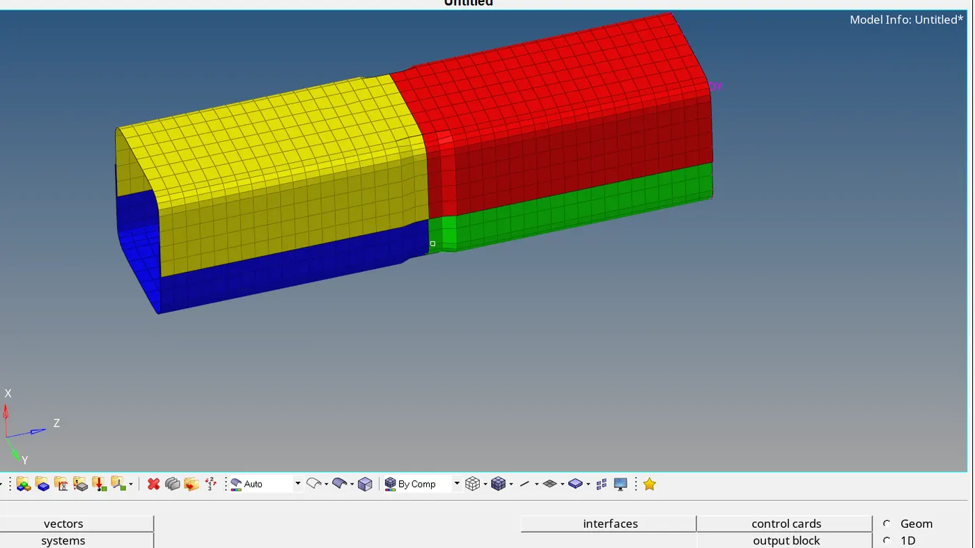
- Now, in above case we created the notch by considering whole secion of model. But, in this case only opposite faces of the model have to be selected and notch has to be created.
- Compare the results with case having two nothces and the one with without notch and the one with only one notch.
- Study the deformation time, where deformation is taking place.
COMPARISON OF CASES
Simulation observation :
We are observing the cases as follows :
- Model with and without notch.
- Failure of model with notch at different places.
- Creation of interface type_11.
EFFECT OF NOTCH ON DEFORMATION : - The failure of part takes place near notch section. Due to less material available there material failure takes place early in case of parts which have notches.
- But, when part doesn't have notch the behavior of failure is different. Crush will fail first near the Rigid wall support and then the failure of part will progress towards rigid body.
- The reason for failure near notch section could be stress concentration.
- When we compare both parts, failure will occure early in the part which has notch.
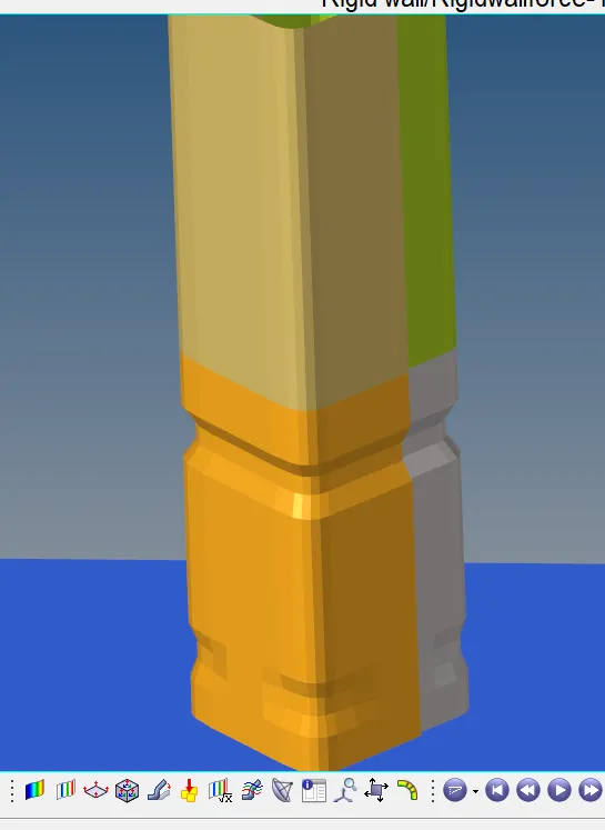
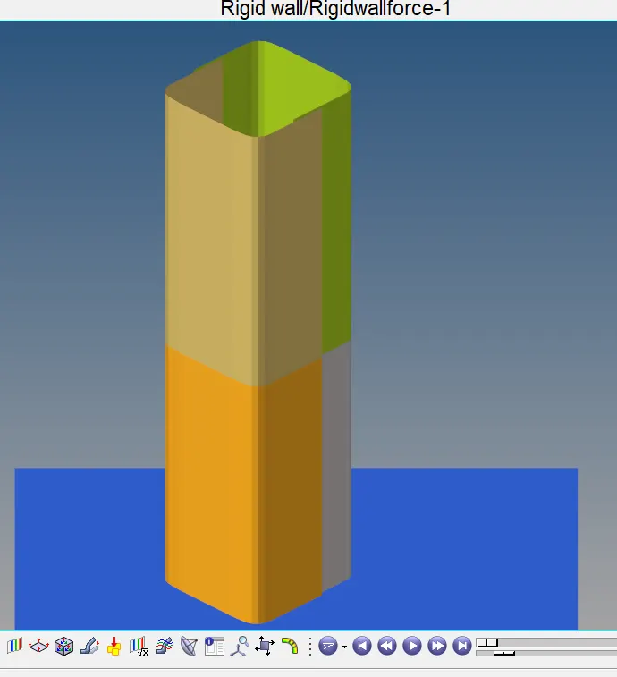
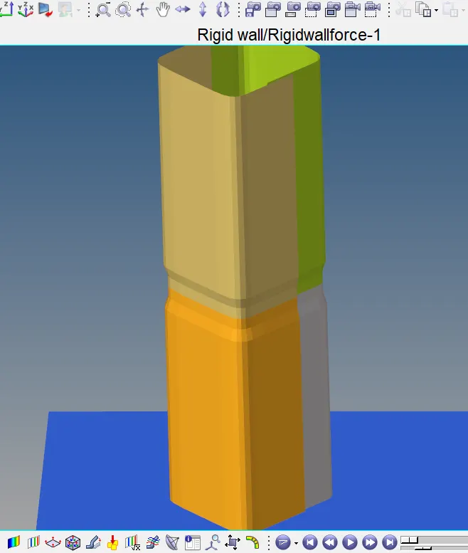
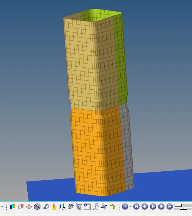
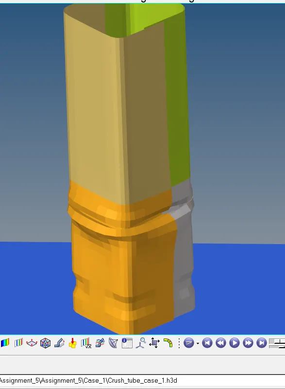
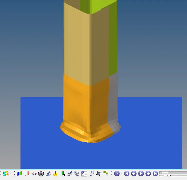
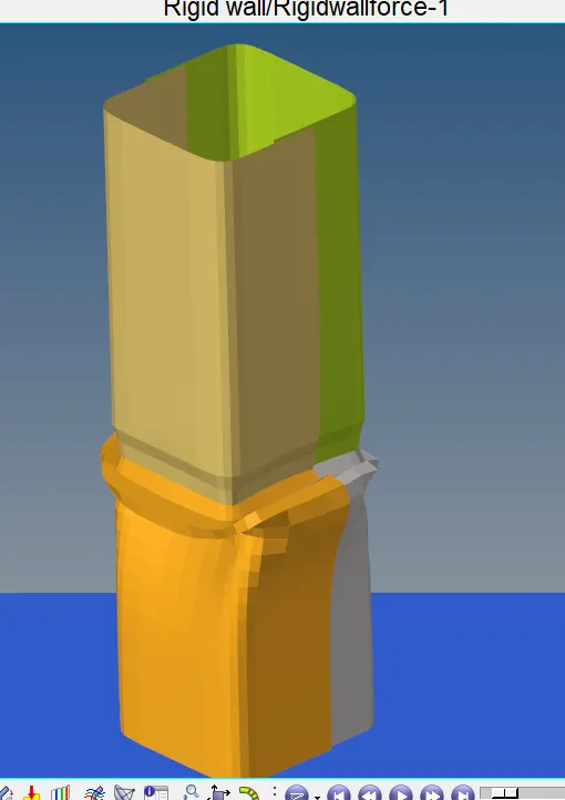
CASE_1 WITH BOTH FULL SECTION CASE_4 / W/O NOTCH CASE_5 WITH NOTCH CASE_6 WITH NOTCH ON
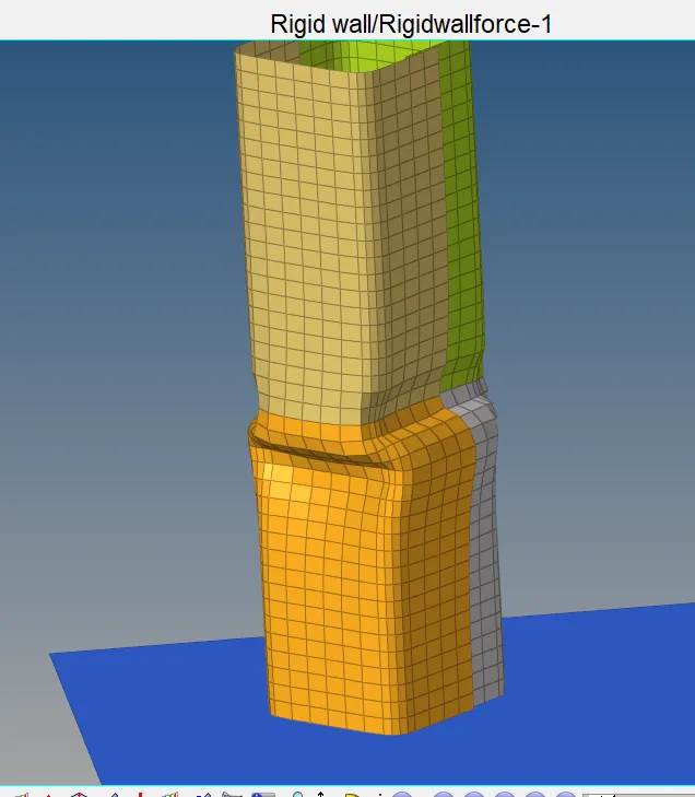
AND PARTIAL NOTCH ON FULL SECTION OPPOSITE FACES ONLY
CASE_1 OBSERVATIONS :
- Crush tube has 1 full section notch and 1 notch on only two opposite faces.
- When we apply load on crush tube, failure initiated in between these two notches.
- To be specific failure of part is initiated from notch on full section and progressing towards partial notch.
- The section above full notch is not affected by the applied force till this sectin between two notches gets deformed completely.
- The nature of deformation is compressive in nature. The reason could be the stress concentration in area having notch.
CASE_4 OBSERVATIONS :
- In this case all the notches have been removed and surface made completely flat and deformation follows completely different path.
- In this case deformation initiated from support side i.e., side having rigid wall and progressed towards another end of crush tube.
CASE_5 OBSERVATIONS :
- In this case only one notch is created to observe how does the crush tube will behave in failure, when notch is created at different locations.
- But, there was again same behavior of deformation. Failure initiated from notch again and progressed towards rigid support.
CASE_6 OBSERVATIONS :
- In this case notch is created on only opposite sides.
- Again the crush tube followed the same pattern. crush tube deformed near notch first.
- The crush tube deformed like it was getting folded on itself.
- When we compared deformation of case_5 and case_6, there was slight difference in the way they deformed.
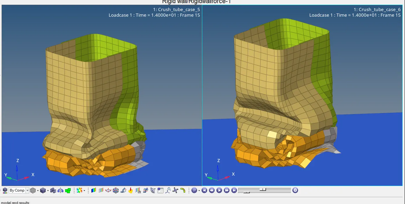
- In this image, left side model is of case_5 and on the right side is case_6. The difference is in case_5 the tube is moving inside from all sides. But, in case_6 tube is moving inward from the sides where there was no notch and moving outward from the side having notch.
- So, there are various behaviors of model with and without notch.
CONTACT ENERGY :
- There were changes in the graph of contact energy plotted.
- Same folder of screen-shots of contact energy is attached along with this report.
- At start of simulation there was very less contact energy available in model. As soon as the model starts folding itself i.e., the model was folding on itself while deforming so there might be penetration in the model at end of simulation.
- Thus, a sudden rise in contact energy has been observed.
- So, the graph basically consists of a platau and a linear curve.
- Contact energy was observed highest when we applied type_11 interface contact along with type_7 and type_2.
- The reason behind increase in contact energy could be penetration, friction or the forces of contact are increasing between two mating elements. Or this might be due to bodies are experiencing more deformation.
INTERNAL ENERGY
- We plotted graphs of internal energy for all the cases. In most of the cases internal energy is same throughout all the cases.
- The graph of Internal energy is measure of how much energy the elements are absorbing when the crush tube is being deformed.
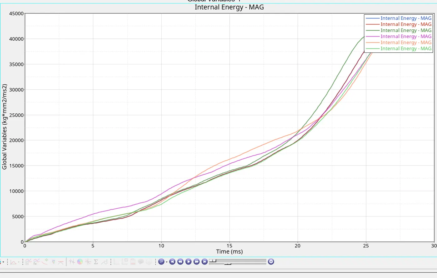
- As we can observe in above image the graph of internal energy is same in all cases. There is no significant change in internal energy.
RIGID WALL FORCES :
- In crash analysis we are doing the analysis of parts or models which are being forced towards the wall. In such cases walls are made more stiffer than the parts whose analysis is being carried out.
- Which means that when the part come in contact with rigid wall, the rigid wall applies force on the part itself. Hence it is very important to measure the forces/reaction forces which are being applied on the parts by rigid walls.
- We observed that rigid wall forces are maximum when contact type_11 was created and it is minimum when notches were removed from model.
CONCLUSION :
- So, from this results we can conclude that notch present in the part could lead to failure. As we observed there was clearly difference between deformations when we compared cases with and without notch.
- Failure initiated from the notch and towards rigid wall. Also, failure initiated earlier in case of notch.
- Hence, we can conclude that notch leads to stress concentration in part which reduces capability of material to resist forces and thus part fails near notch section.
MESH CHALLENGE :
OBJECTIVE :
- Mesh the given component of bumper with mesh size of 6mm.
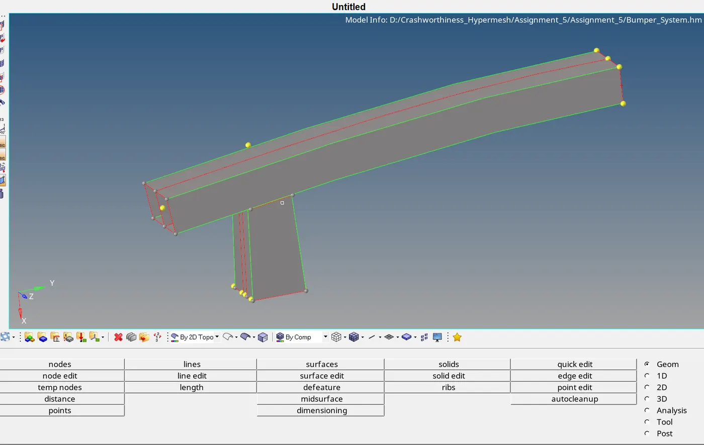
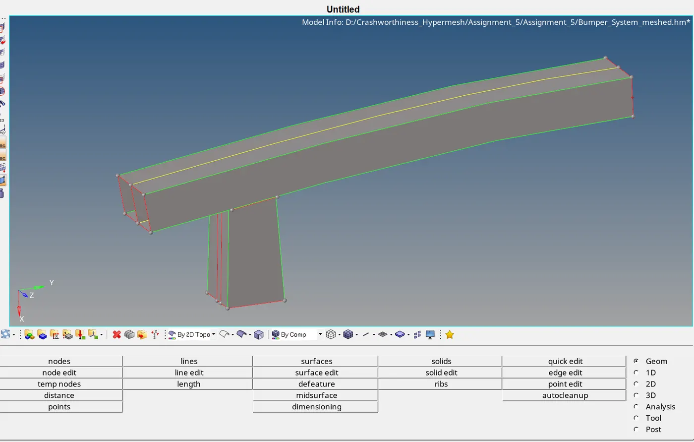
CAD MODEL
- Join all the surfaces which are shown by red colour lines, which states that they are not connected to their adjacent parts.
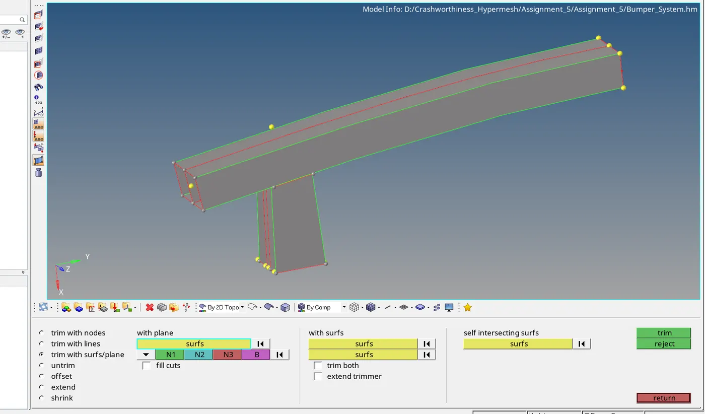
- To connect them to their adjacent parts, go to surface edit --> trim with surface/plane --> select 'with surfs' --> select the surfaces to be intersected one by one --> click on trim.
- Now, go to 2D panel --> automesh --> select the surface to be meshed --> give element size as 6 --> click on mesh.
- Adjust number of elements on both the edges of surface. Mesh all the surfaces.
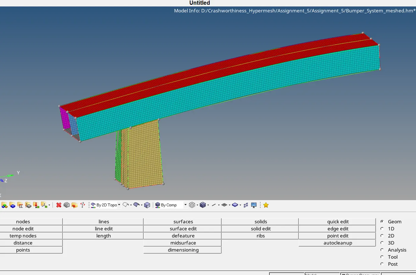
- This is image of meshed part with element size 6mm.