Assignment 5-RADIOSS Interfaces & Study of Effect of Notches Challenge
Report on Assignment 5-RADIOSS Interfaces & Study of Effect of Notches Challenge
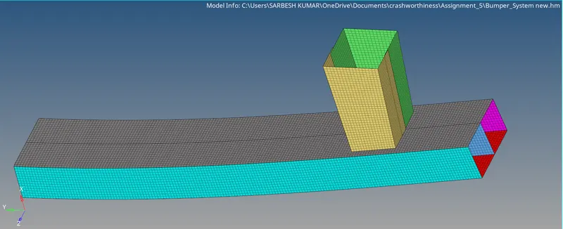
Create the mesh for bumper assembly,mesh size should be 6mm.
steps
1) Import the model , First we have to Rectify the Geometrical Errors for that we have to do Autocleanup with the given target element length equals to 5 units and observe the model carefully , check the connectivity and suppress the unnecessary lines and the models should have closed geometry
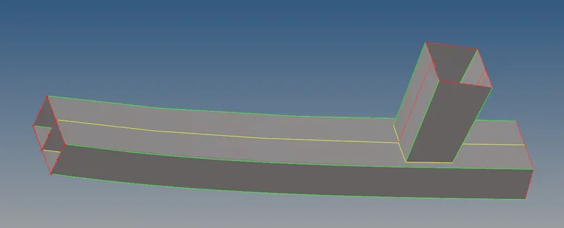
2) Now perform meshing operation one by one , create a mesh on the mid surface goto 2D>automesh>select the surface>give element size =6>click on mesh
Few points must be Obey during the meshing
- No Tria element on the edges (free edge , share edge ,non- manifold edges, )
- No opposite trias in the Mesh
- Not trias should touch each other (no back to back trias)
- No trias must touch features (Embosses,Fillets , Holes, Logos, Dog Houses, Weldings etc.)
- There should be an even number of nodes on the holes opening
- No rotational quads
- No pattern Trias
Check mesh flow and make it proper for that some frequently used commands Rebuild mesh (2D>Rebuild mesh>select elements>click on rebuils), Edit element (2D>Edit element>create/split/combine), smooth option (2D>smooth>select element,enter iterations>smooth), quality index (2D>quality index>QI setting/cleanup tool) in quality index we have both option Quality index and cleanup tools we can use both options, in QI we can check quality criteria and we can set display thresholds, and in cleanup tools we can split,collapse, combine, optimize element node etc, we can use Replace option to connect two nodes or to remove edges
| Cases | RWALL forces | Remarks and conclusion |
|
1) Run the crash tube model as it is. |
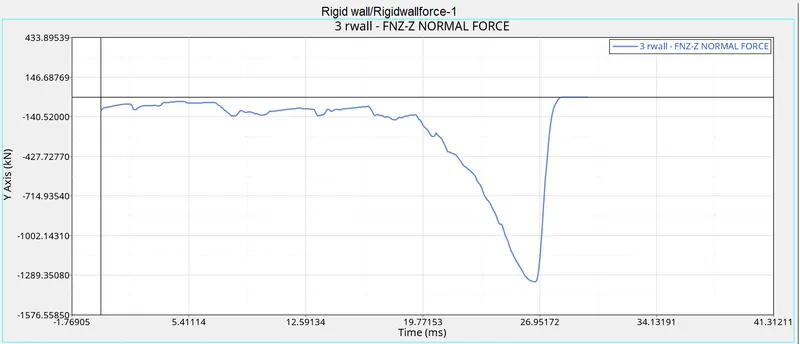 |
Since this is first case , we can observe that , the forces are acting -ve z-z plane , hence it is appeared in fourth coordinate , and we can see that pick is occured from time 19 sec to 26 sec (approx) This is because the total workdone by forces is convert into K.E + P.E + contact energy hence the at time between 19 sec to 26 sec (approx) as distance to be travel by forces is less hence forces are increased w.d=F*x=change in K.E x-decreases=>F-increases |
|
2)Change the Inacti=6 and run. |
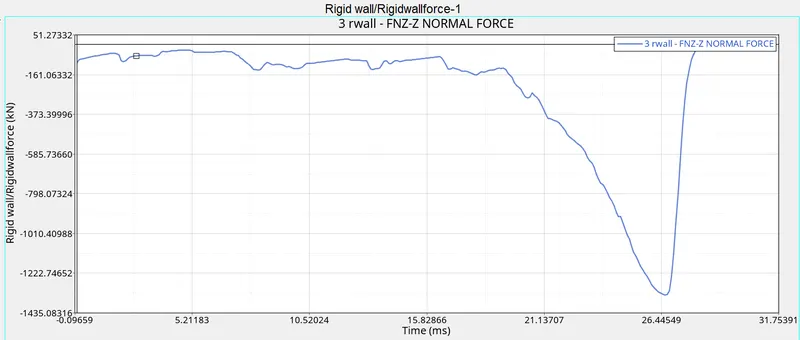 |
Same point as we have discussed in case-1 but due application of Inacti=6 it will remove initial penetration, The resistive force is nonlinear with respect to the penetration of the slave node into the gap and is a function of the penetration value and rate. so thats why there will be a less Resistive force is generated due to which the pick of graph of Case-2 is less that pick of case-1 |
|
3) Create the type 11 contact and run. |
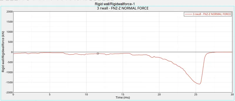 |
Same point as we have discussed in case-1, but here in this case due to activation of all the recommended parameter and Type-11 contact , there is a only one difference between type-7 & 11, in type 11 the edge related intersection can be removed but it is not done in type7.rest of all the recommended parameter are same for both type 7 & 11 In type-11 the master and slave are component's edge line So, in this case due to activation of all the recommended parameter and Type-11 contact, there will be a less penetration and less intersection, hence less resistive force is required to push the slave node out of the master surface hence the pick magnitude of the force is reduced |
|
4) Remove both notches and remove boundary condition on rigid body node then run. |
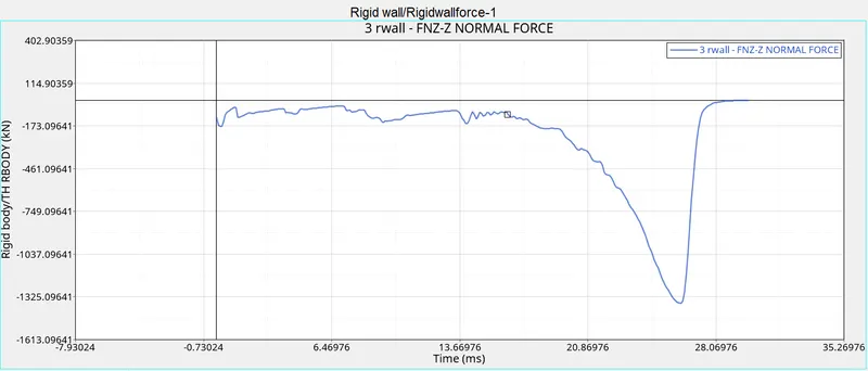 |
Notches:- the main reason for using notches in the crash tube is it will discipates the energy and give the proper direction for deformation In this case we are going to mainly compared with notches in case-1,2,3 with the case-4 by removing notches the deformation will not takes place in proper way and there will be a unappropriate energy discipation and hence at the last seconds there will be a more amount of force but less amount of material to deform |
|
5) Create a new notch in the middle ,select the whole section and run. |
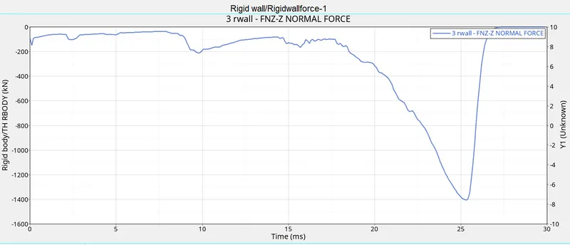 |
By creating notches in the middle of the tube the tube get deformed in more proper way as compared to case-4 that is for the pick of the curve is more in this case as compared to case-4 |
|
6) Create a new notch with nodes only from opposing 2 faces and run. |
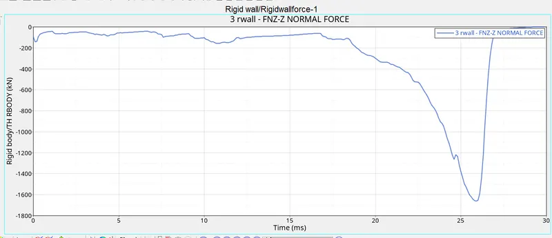 |
by creating the notches at both end and opposite faces there is more proper deformation as compared to case-5 |
Recommende parameters
- remove all the intersection to get physical results and to avoid solver error
- Igap=2, set variable gap to take into account the true distance between the parts
Gapmin.0.5, specify minimum thickness of the model to avoid numerical issues, typically half of the thinnest part - Inacti=6, Remove initial penetrationwhere possible , reduce to less than 30% of the defined gap value and adjust the gap with inacti
- Istif=4, set stiffness of interface based on the minimum of master and slave
- Stmin=1000N/mm, specify a minimum stiffness in the contact because of the element deletion
- Idel=2, Remove slave nodes from the contact because of element deletion
- Iform=2, Sliding forces are computed using stiffness parameters of the interface, usually results in bigger time step.Define physical value for the material contact and part thickness , even if rigid , They are used for the contact stiffness and the gap definition.
| Cases | Contact forces | Remarks and conclusion |
|
1) Run the crash tube model as it is. |
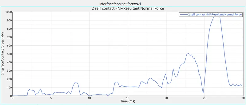 |
In contact forces there is more variation in the curves as contact increased with respect to time |
|
2)Change the Inacti=6 and run. |
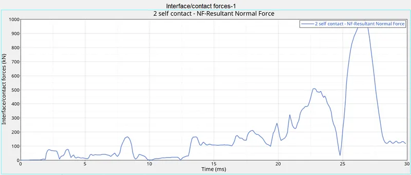 |
by using Inacti=6 there is more pick as compared to case-1 because by removal of initial penetration , the applied forces are completetly encounter in deforming element of the same component |
|
3) Create the type 11 contact and run. |
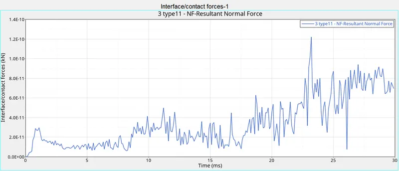 |
there is more variation in contact forces w.r.t time as compared to case-1,2 due appplication of recommended parameter and type-11 there not intersection and penetration betn slave and master surface , the contact forces are completely engaged in element of same component to deform it the hike in pick from start to end is more uniform as compared to above cases |
|
4) Remove both notches and remove boundary condition on rigid body node then run. |
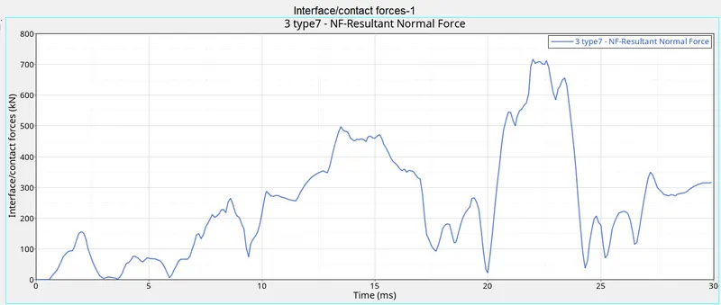 |
By removing all the notches the distribution of contact forces not proper. Hence there more pick and valley in this case |
|
5) Create a new notch in the middle ,select the whole section and run. |
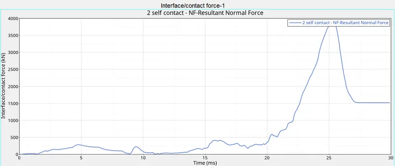 |
In this case as notches are provided in the midle the contact forces are distributed properly but at last seconds pick is too high w.r.t time because at last less materials are available to deform but forces are remain too high |
|
6) Create a new notch with nodes only from opposing 2 faces and run. |
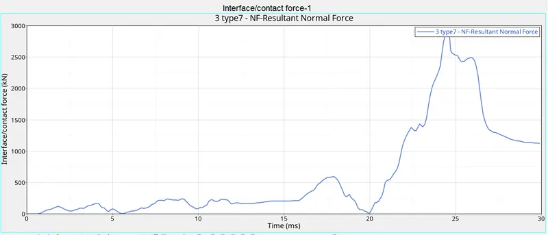 |
by apply notches at both the ends and opposite faces there is proper distribution upto 20 sec after that pick is rise and again pick is falling down due to presence of notches at last end , |
| Cases | Internal Energy | Remarks and conclusion |
|
1) Run the crash tube model as it is. |
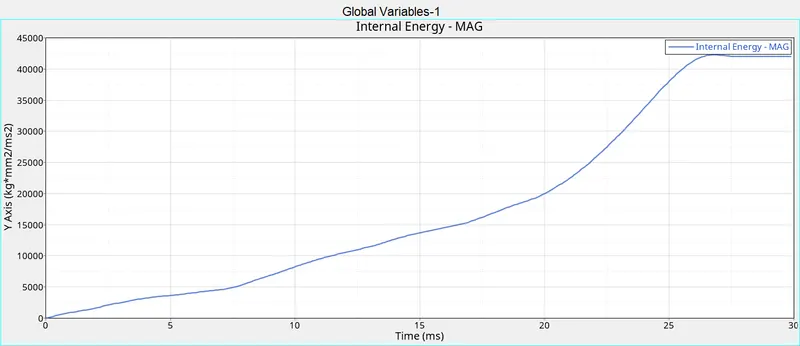 |
as we have discused in above case, due to workdone by the applied force is changes in to K.E , and as per coservation of energy the K.E is changes to P.E (stored) hence the internal energy is increased w.r.t time the effects of forces cause in rise of internal energy |
|
2)Change the Inacti=6 and run. |
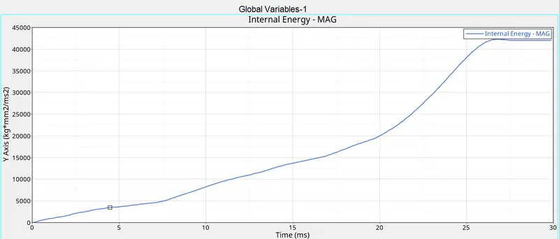 |
Here the variation is almost same as compared to case-1 |
|
3) Create the type 11 contact and run. |
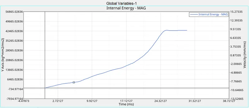 |
Here the after 24.32 sec the internal enrgy is constant w.r.t time due to less intersection and less petration losses of energy in other form is reduced |
|
4) Remove both notches and remove boundary condition on rigid body node then run. |
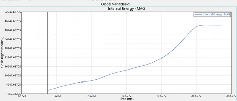 |
by removing all the notches the variation of energy is more i.e losses in other form is more after 25sec the variation is constant |
|
5) Create a new notch in the middle ,select the whole section and run. |
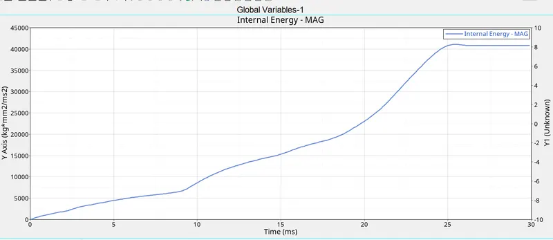 |
By creating notches in the middle the variation more uniform due proper discipation of energy |
|
6) Create a new notch with nodes only from opposing 2 faces and run. |
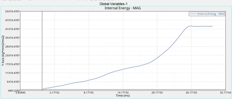 |
By creating notches at the both ends the energy discipation is more proper than case-5 |
| Cases | Time History (Displacement) | Remarks and conclusion |
|
1) Run the crash tube model as it is. |
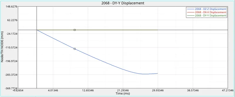 |
Due to applied external force there will be a displacement of nodes w.r.t time |
|
2)Change the Inacti=6 and run. |
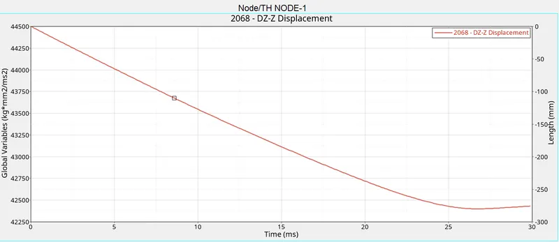 |
Here displacement is more as compared to case-1 due to less initial penetration |
|
3) Create the type 11 contact and run. |
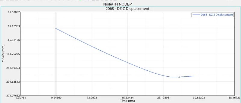 |
Here displacement is more as compared to case-1,2 due to less initial penetration and less intersection |
|
4) Remove both notches and remove boundary condition on rigid body node then run. |
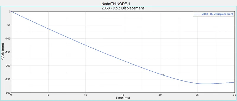 |
By removing notches the elements are not deformed in proper way , hence there will be more displacement as compared to above cases |
|
5) Create a new notch in the middle ,select the whole section and run. |
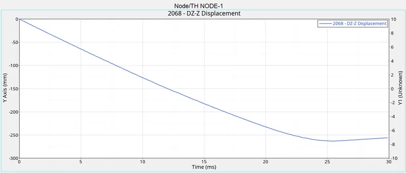 |
there is not significant variation w.r.t case-4 |
|
6) Create a new notch with nodes only from opposing 2 faces and run. |
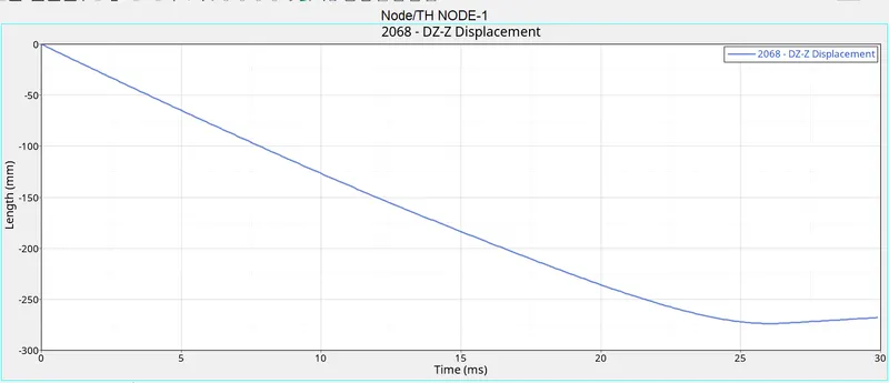 |
there is not significant variation w.r.t case-4,5 |
| Cases | Time History (Velocity) | Remarks and conclusion |
|
1) Run the crash tube model as it is. |
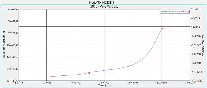 |
As we know that impulse momentum theorem the applied external is equal rate of change of momentum, hence as force is increased the velocity will also increase we can observed that as force is increased the velocity will also increase but after time 27.24399 sec the velocity is constant because of constant acceleration |
|
2)Change the Inacti=6 and run. |
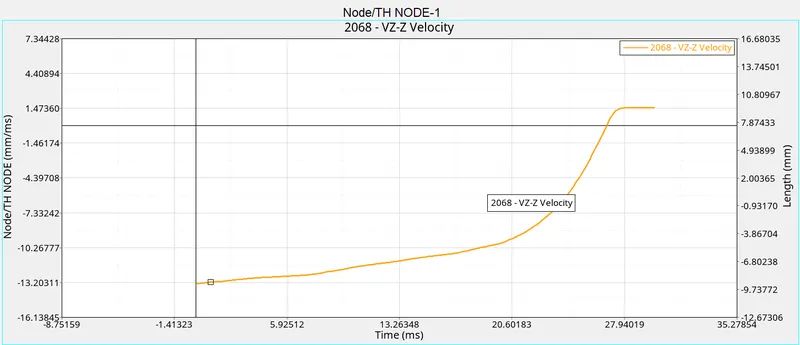 |
Due to Inacti=6 no initial penetration , so elements are free to move , that's why velocity is more as compared to case-1 |
|
3) Create the type 11 contact and run. |
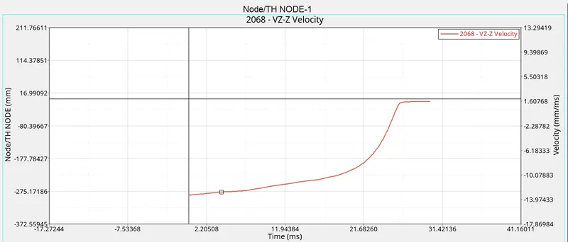 |
Due to application all the recommended parameter and type 11 no initial penetration , no intersection , stiffness is also consider , due to all the reason the velocity is slower that case-2 |
|
4) Remove both notches and remove boundary condition on rigid body node then run. |
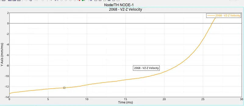 |
Due to removing noteches , the deformation is not proper and nodes are moving faster in time range 15 to 25 sec , as compared to above cases |
|
5) Create a new notch in the middle ,select the whole section and run. |
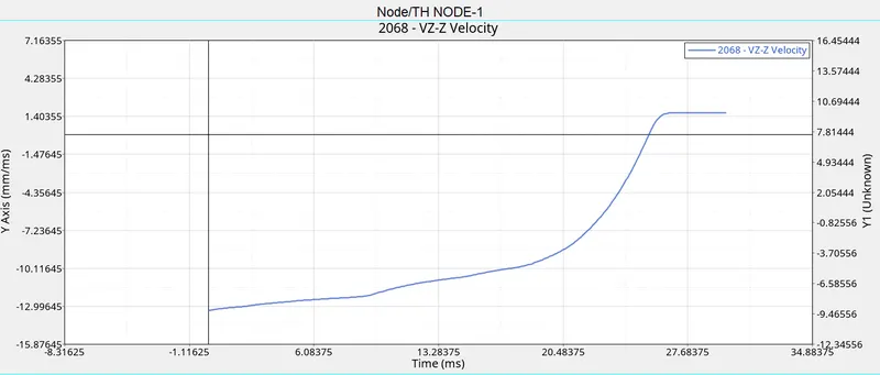 |
Due creating notches in the midle , the middle portion will deform first and there is proper way to deform the material , hence velocity get lower as compared to case-4 |
|
6) Create a new notch with nodes only from opposing 2 faces and run. |
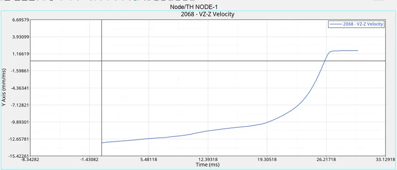 |
Due creating notches at the both ends and opposite faces ,there is proper way to deform the material , hence velocity get lower as compared to case-3 |
All the files are zipped and attached