Assignment 5-RADIOSS Interfaces & Study of Effect of Notches Challenge
Objectives :
- Creating the Mesh For Bumper Assimbly with target mesh size of the 6 mm.
- Analysis of the Crush Tube Model with verious parameters change .
- Running the simulation of all the scenario .
- Anlysing effect of the Notches on the Energies .
- Ploting the Various Energies for study .
Bumper Assembly :
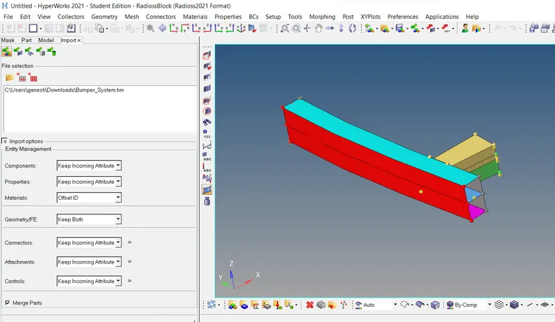
- Model is imported using the Import model Tool as ,
Geomerty Cleanup :
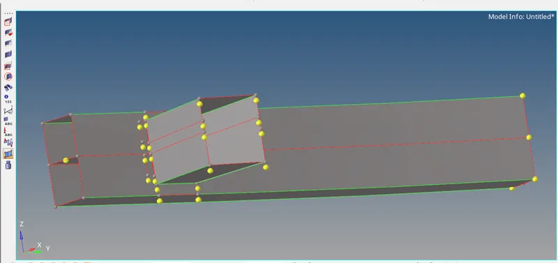
- While importing the Model, some surfaces are gets seperated from each other can be seen below .
- Some Free nodes are also present whch need to be taken care .
- This Nodes are deleted usinh the clear node Tool .
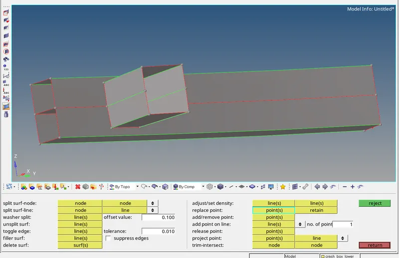
- Some points are replaced by another points to make the proper connection using the Quick Edits Tool .
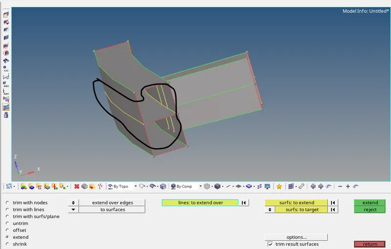
- Now Upper and Lower surfaces of the are connected with the Bumper Beam Lower by using the Extend Surface Tool .
Mesh Creation :
- All the surfaces are Meshed using the Automesh tool .
- While meshing Target Mesh size kept as 6 mm .
- For the elements of different surfaces Equivalence nodes Tool is used .
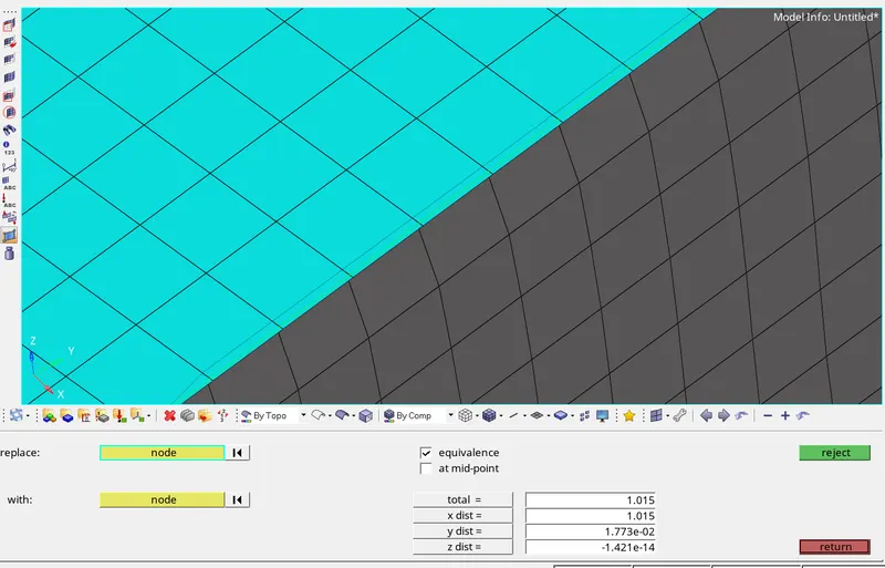
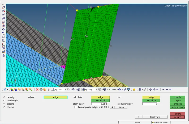
- Meshing on the Crash box Surfaces were not properly creating because of the some surface issue .
- Then Meshing of the this surface is done by Ruled - 2D mesh Tool as ,
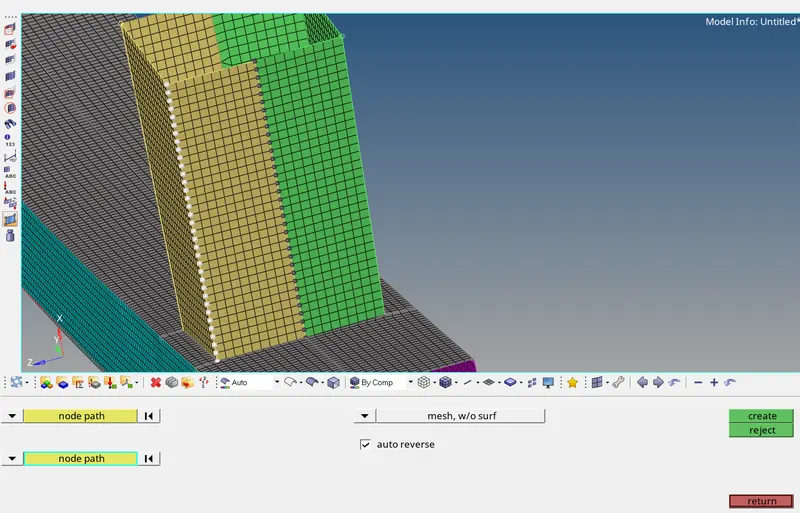
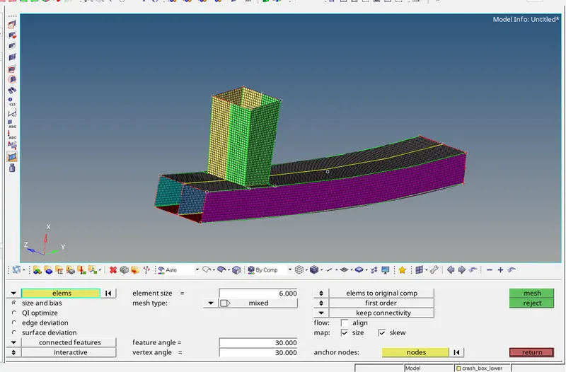
- The Final Model Image can be seen below as,
Crash Tube Model :
Case 1 :
- Model Is imported using the Import Solver deck Tool with file type Radioss block .
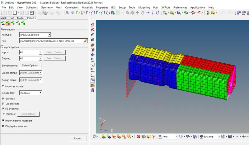
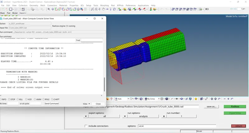
- This Model is analysed using the Radioss Solver as it is , as per the 1st scenario .
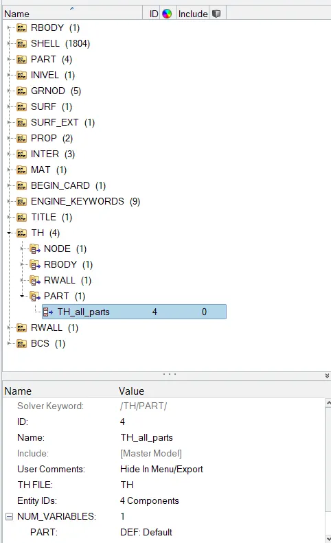
- TH/PART is created for all the parts .
Plots :
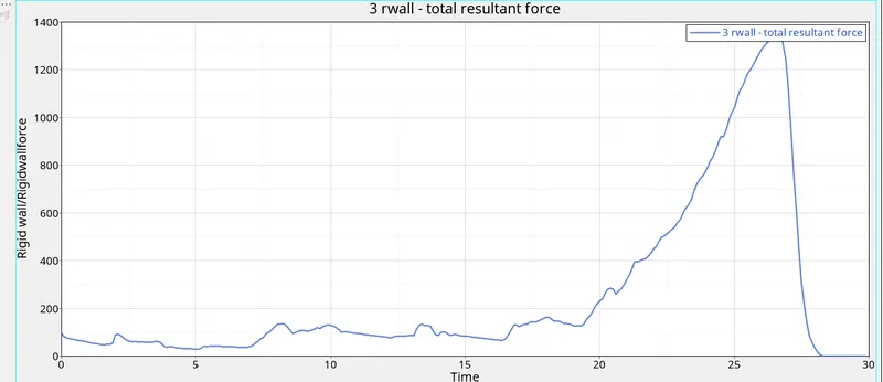
Rigid Wall force :
Internal Energy :
Kinetic Energy :
Contact Energy :
Total Energy :
Results :
- As TH/PART Created for all the parts we get the Time History block for all the Parts in T01 .out file .
- As the Shell elements properties are changed to the improved shell properties , Hence the Hourglass Energy is Optimesed/controlled to the Zero .
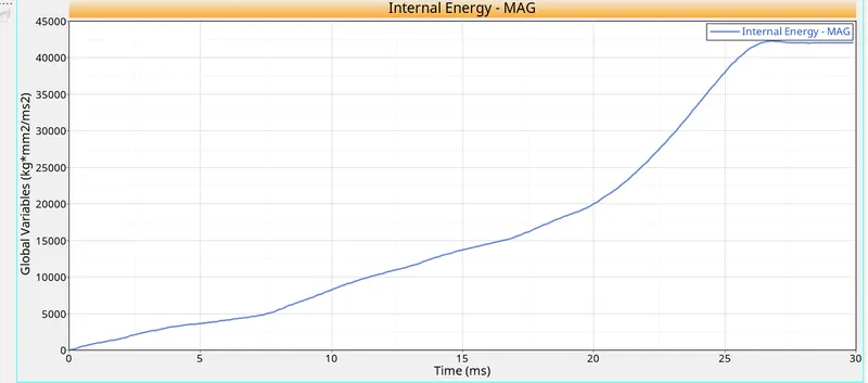
- From Internal Energy Graph , we can se that the Internal Increases gradually .
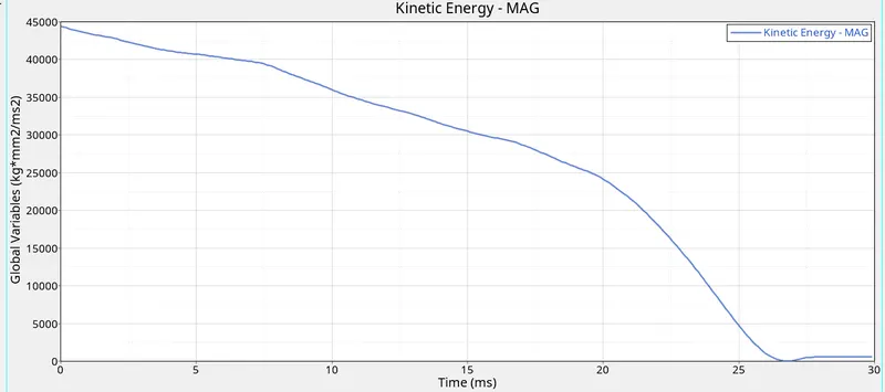
- Kinetic Energy High initially comes down to the almost Zero at end of the Simulation .
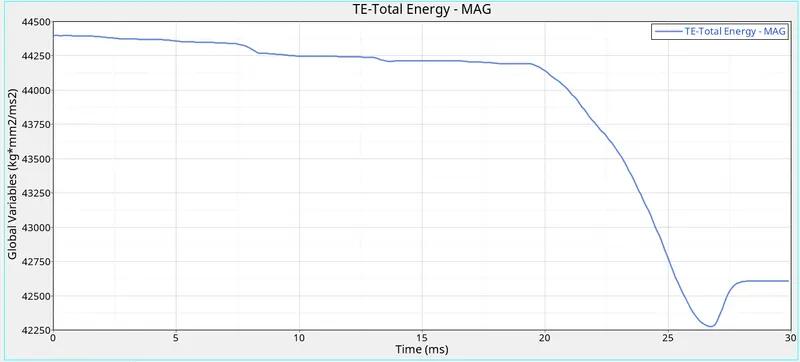
- Here the Energy Error is ranges from the -0.0 % to - 3.8 % and the Mass Error is Zero .
- Acceptable Error ranges for Energy Error is -15 % to +5 % and the Mass Error is max + 2 % of the Total Mass .
- Hence this results are acceptable for further Process .
Case 2 :
- For the Case 2 , The Same model from 1st case is used for further process .
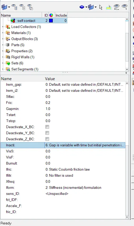
- As per Requirment , In Typer 7 contact ( self contact ) , the Incative is changed to the 6 .
- This Inactive is Used to remove the Initial Penetration .
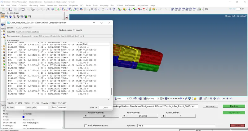
- Now Model is Analysed using the Radioss Solver and SImulated in the Hyperview .
Plots :
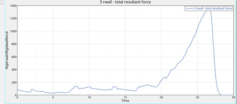
Rigid Wall Force :
Internal Energy :
Kinetic Energy :
Contact Energy :
Total Energy :
Results :
- As the Shell elements properties are changed to the improved shell properties , Hence the Hourglass Energy is Optimesed/controlled to the Zero .
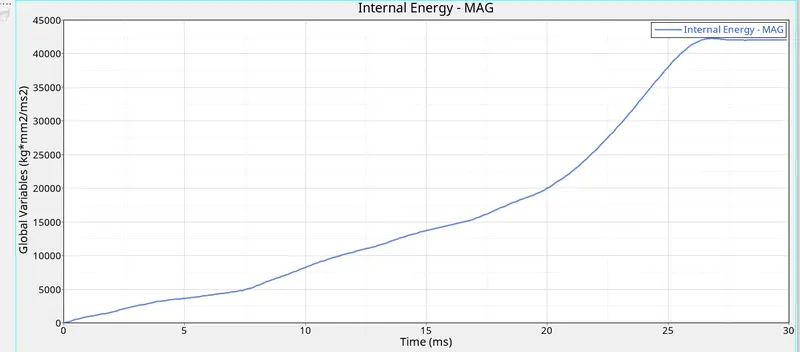
- From Internal Energy Graph , we can se that the Internal Increases gradually .
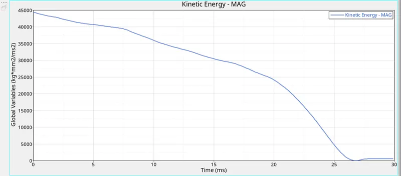
- Kinetic Energy High initially comes down to the almost Zero at end of the Simulation .
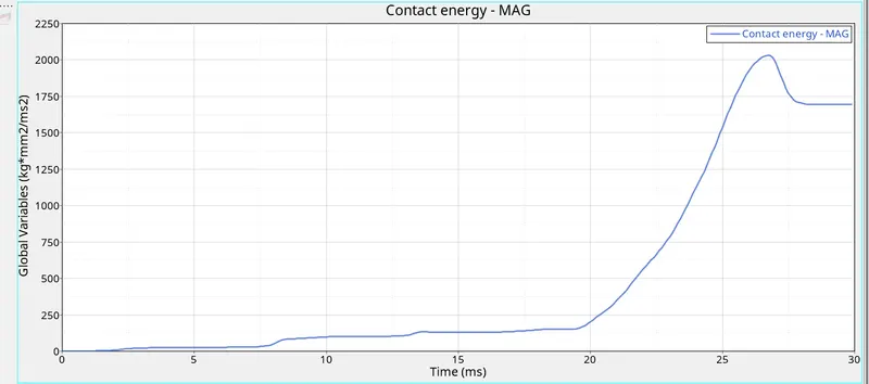
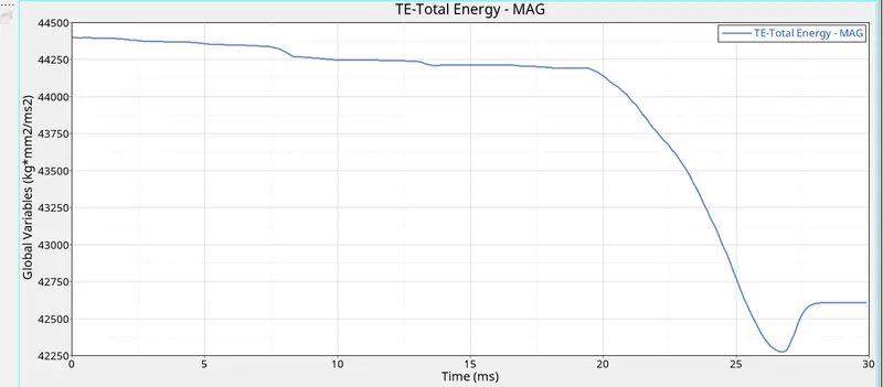
- Here the Energy Error is ranges from the -0.0 % to -5.7 % and the Mass Error is Zero .
- Acceptable Error ranges for Energy Error is -15 % to +5 % and the Mass Error is max + 2 % of the Total Mass .
- Hence this results are acceptable for further Process .
Case 3 :
- For the Case 3 , The Same model from 2nd case is used for further process .
- As per requirment , Type 11 Contact Is created .
- This Type 11 is used for Edge to Edge Interface of the elements and surfaces .
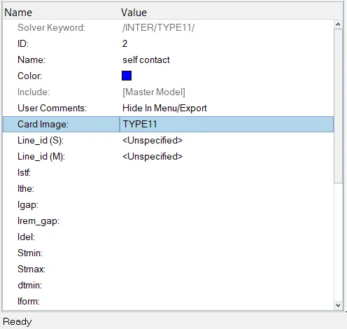
- Then This Model Analysed by the Radioss Solver and Simulated using the Hyperview .
Plots :
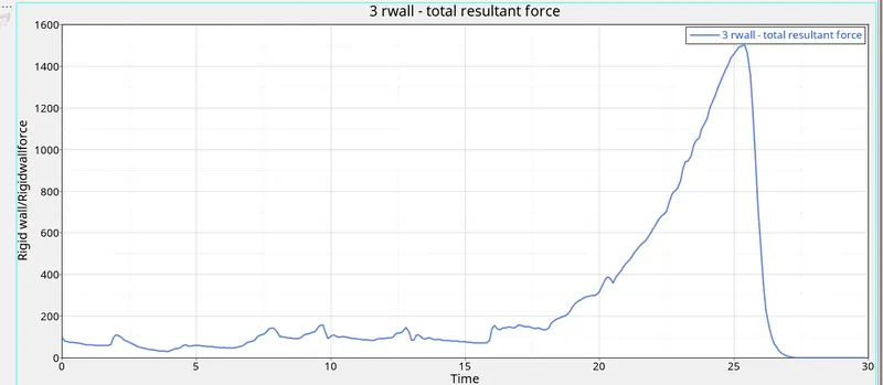
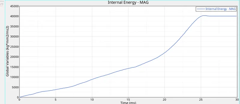
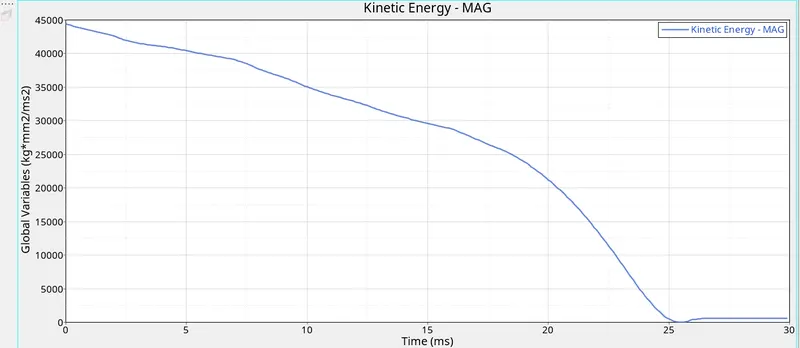
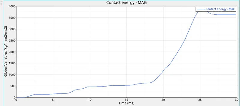
The Various Energies plots are ploted in the Hypergraph 2D .
Rigid Wall Force :
Internal Energy :
Kinetic Energy :
Contact Energy :
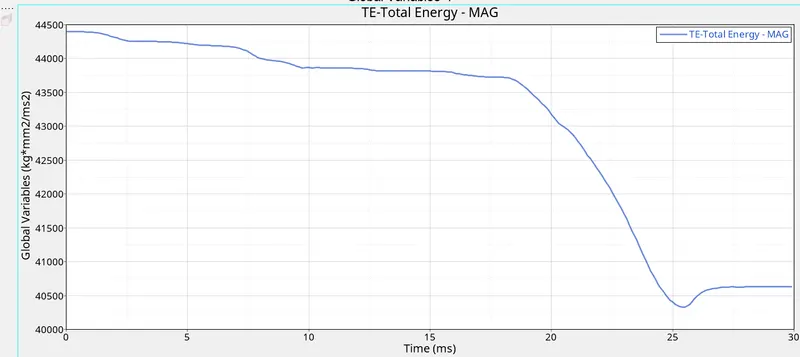
Total Energy :
Results :
- As the Shell elements properties are changed to the improved shell properties , Hence the Hourglass Energy is Optimesed/controlled to the Zero .
- Kinetic Energy High initially comes down to the almost Zero at end of the Simulation .
- Here the Energy Error is ranges from the -0.0 % to -8.6 % and the Mass Error is Zero .
- Acceptable Error ranges for Energy Error is -15 % to +5 % and the Mass Error is max + 2 % of the Total Mass .
- Hence this results are acceptable for further Process .
Case 4 :
- For the Case 4, The Same model from 3rd case is used for further process .
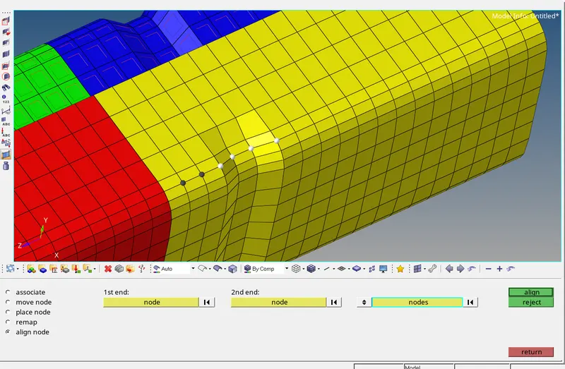
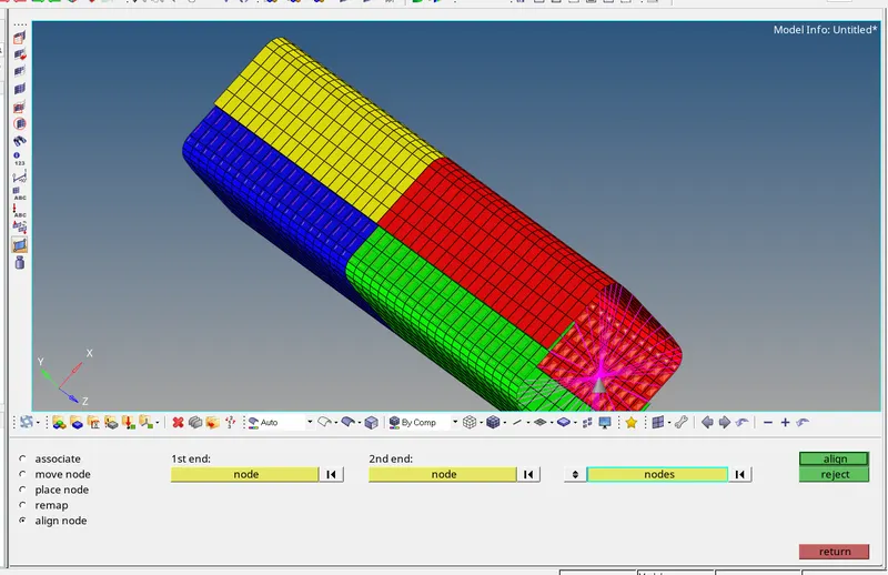
- Both notches are removed of the model by aligning the nodes in a straight line.
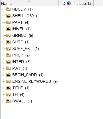
- Boundry Condition also removed from the Rigid body node .
- Its done by deleteing the Boundry Condition Card from the Solver browser .
- Now this model is analysed by the Radioss Solver and Simulated into the Hyperview .
Plots :
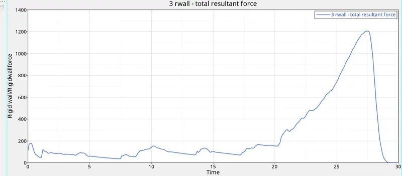
Rigid Wall Force :
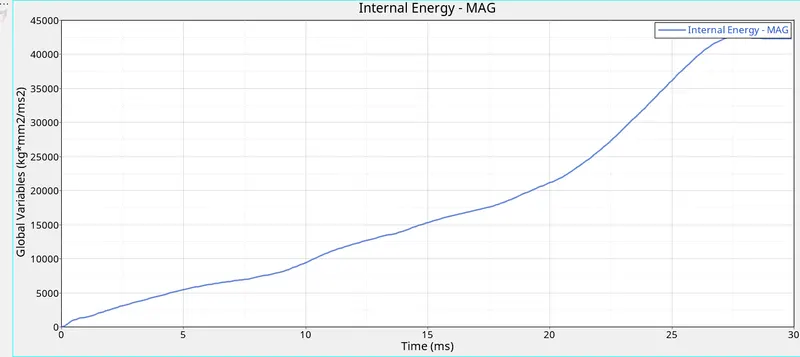
Internal Energy :
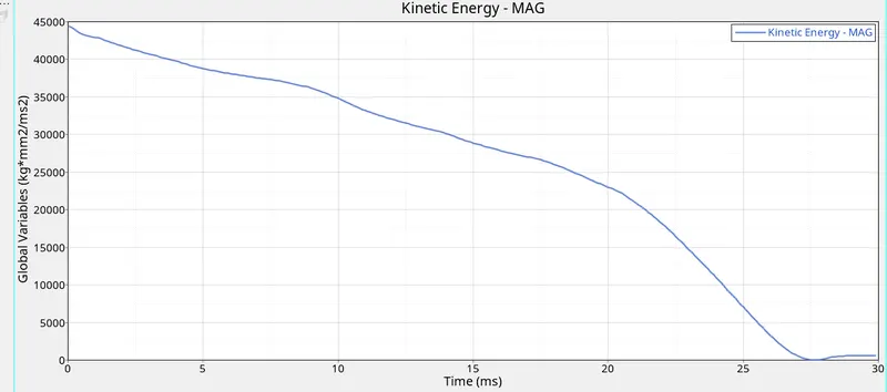
Kinetic Energy :
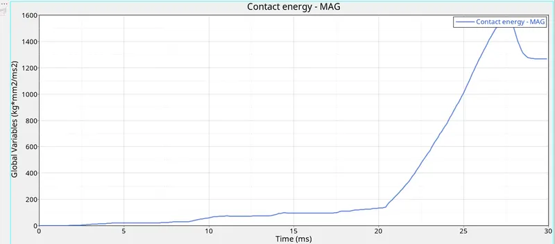
Contact Energy :
Total Energy :
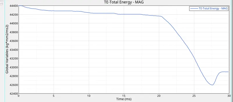
Results :
- Improvement in the Shell elements properties results in the Hourglass Energy is Optimesed/controlled to the Zero .
- Here the Energy Error is ranges from the -0.0 % to -9.7 % and the Mass Error is Zero .
- Acceptable Error ranges for Energy Error is -15 % to +5 % and the Mass Error is max + 2 % of the Total Mass .
- Hence this results are acceptable for further Process .
Case 5 :
- For the Case 5 , 4rt case model is used .
- New Middle Notch is created by selcting the Whole Section .
- This Done by Penetration Check Tool from Tool option from manu Bar .
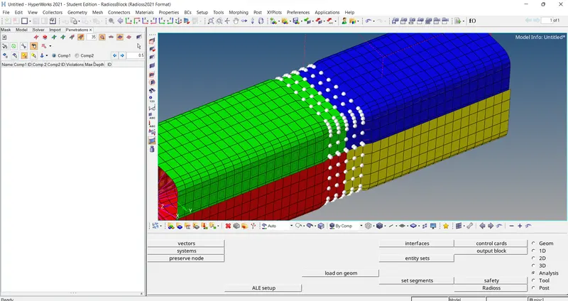
- For analysing the Model Radioss Solver is used and made to simulate in the Hyperview .
Plots :
Rigid Wall Force :
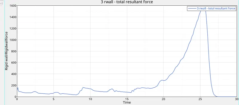
Internal Energy :
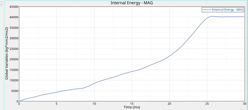
Kinetic Energy :
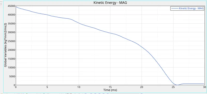
Contact Energy :
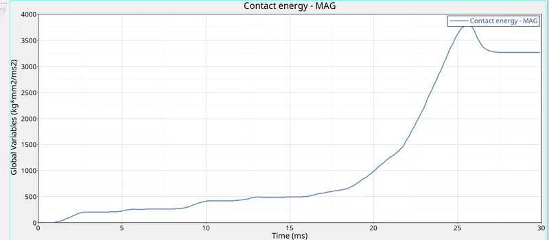
total Energy :
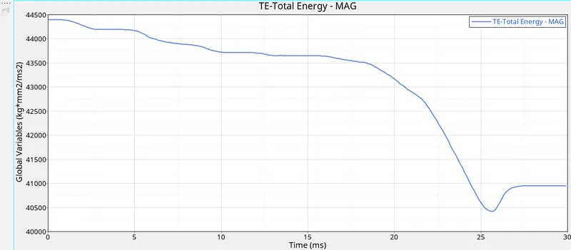
Results :
- As the Shell elements properties are changed to the improved shell properties , Hence the Hourglass Energy is Optimesed/controlled to the Zero .
- Kinetic Energy High initially comes down to the almost Zero at end of the Simulation .
- Here the Energy Error is ranges from the -0.0 % to -8.4 % and the Mass Error is Zero .
- Acceptable Error ranges for Energy Error is -15 % to +5 % and the Mass Error is max + 2 % of the Total Mass .
- Hence this results are acceptable for further Process .
Case 6 :
- Model of the 5ft case is used in 6th case .
- In this case , the Notch is created using the nodes , on the only opposite faces of the model .
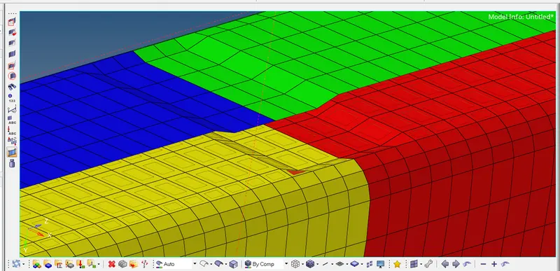
- Then model run using the Radioss Solver and the Hyperview for simulation .
Plots :
Plots are plotted into Hypergraph 2D .
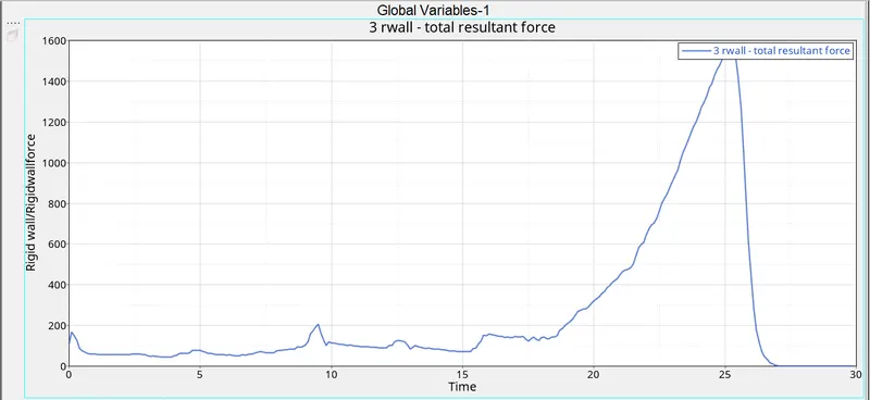
Rigid Wall Force
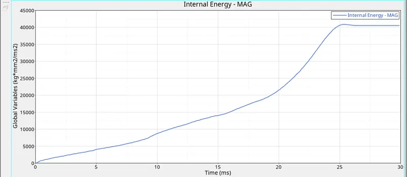
Internal Energy :
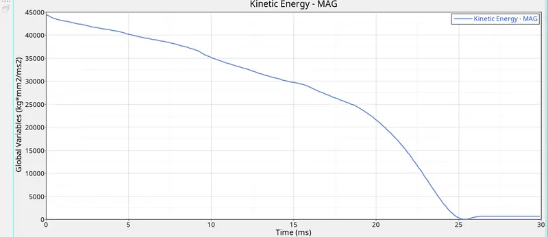
Kinetic Energy ;
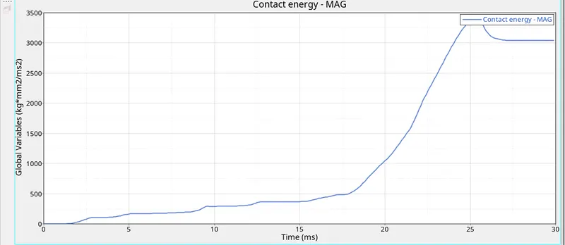
Contact Energy :
Total Energy :
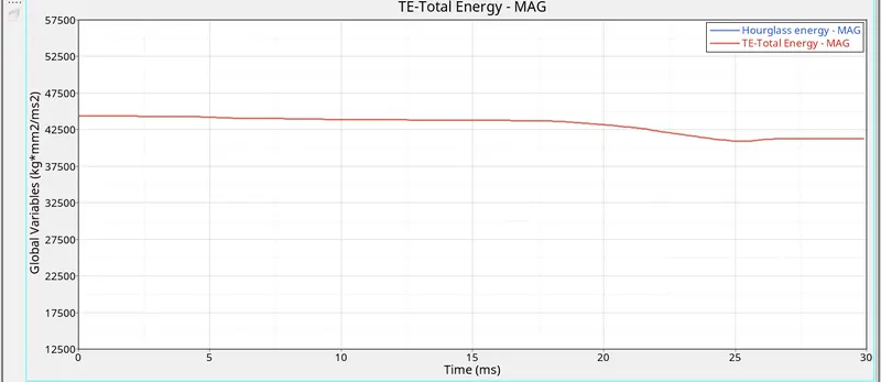
Results :
- As the Shell elements properties are changed to the improved shell properties , Hence the Hourglass Energy is Optimesed/controlled to the Zero .
- Kinetic Energy High initially comes down to the almost Zero at end of the Simulation .
- Here the Energy Error is ranges from the -0.0 % to -7.5 % and the Mass Error is Zero .
- Acceptable Error ranges for Energy Error is -15 % to +5 % and the Mass Error is max + 2 % of the Total Mass .
- Hence this results are acceptable for further Process .
Comparision :
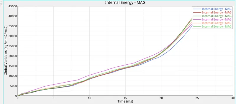
- Internal energy between the Case 2 and the case 3 , is slightly lowerd in case 3 than the Case 2 .
- This is beacause the Noteches in case 3 Which will provide more strength to the model .
- In case 5 ,As there is a Notch present at thw Middle of the model , will take slightly longer time to reach the level of Internal enegry than 1 to 3 cases .
- means the Internal energy in case 5 reach the perticular Value in less cycles than 1st 3 cases .
- Example : To reach the value of the 1093 Internal energy case 5 required 2100 cycles .
- on the other hand for case 1 st 3 cases more than 2700 cycles required .
- In case 6 , The Internal energy will reach early than the case 5 , as the Notch is only present on the opposite faces of the model .
- This Opposite face Notch will oppose less than the Case 5 to the Load Applied on the model .
- Now For Case 4 , to reache the Internal Energy Value Of 1093 requires the only 1000 cycles .
- This Is because the , No Any notch present on the Surfaces of the model in this case 4 .
- This can be seen below as ,
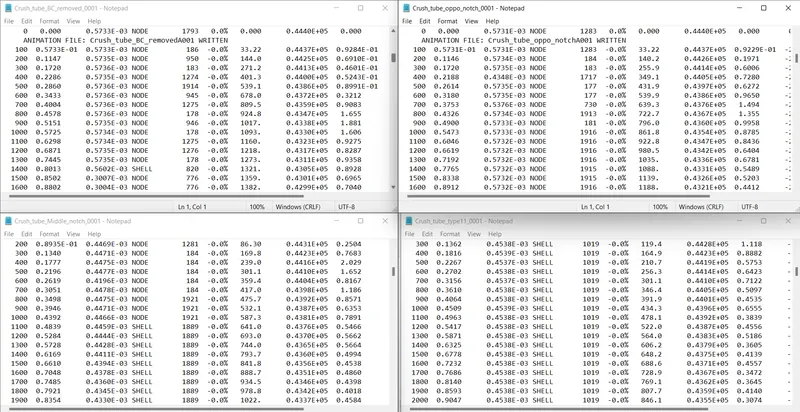
- The Increasing order of the case in term of cylces to reach the value of the Internal energy near about 1100 can be made as ,
- case 4 < case 6 < case 5 < case 3 < case 2 < case 1 .
- The Cases Which have more the Notches , have the more strength than the cases having less notch or don't have any Notch .
- This Notches opposes to the Applied load and Hence the more time required to reach or to change the same amount of the Internal Energy .
- This Notches are Also affects the Kinetic Energy , Total Energy too .
The Internal Energy Change for all the cases can be seen below in graph as ,
The Meshed Bumper model .hm file is attached below .
The Simulation Files of all cases are also attached below .