Assignment 5-RADIOSS Interfaces & Study of Effect of Notches Challenge
MAIN OBJECTIVE;
- Create the mesh for bumper assembly, mesh size should be 6mm.
- Run the crash tube model as it is.
- Change the Inacti=6 and run.
- Create the type 11 contact and run.
- Remove both notches and remove boundary condition on rigid body node then run.
- Create a new notch in the middle, select the whole section and run.
- Create a new notch with nodes only from opposing 2 faces and run.
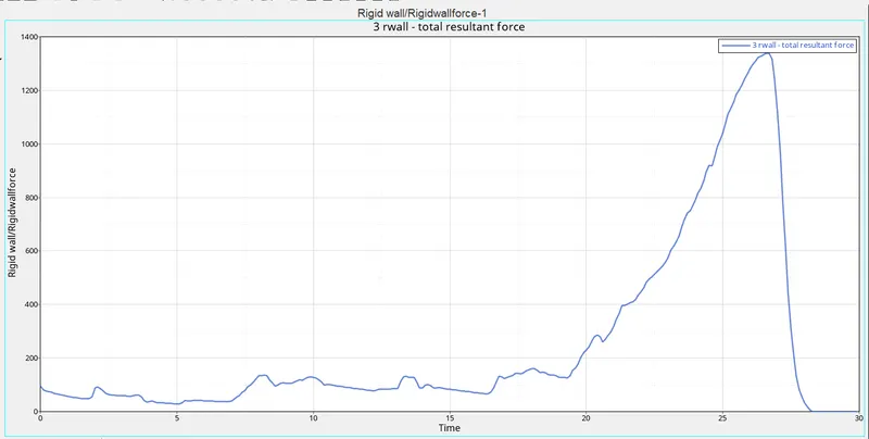
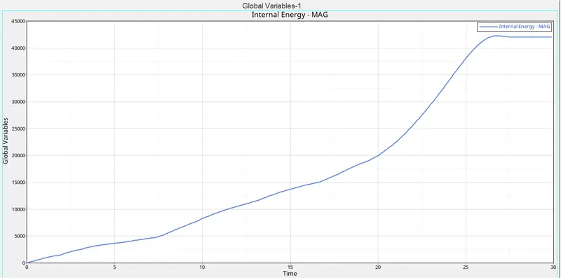
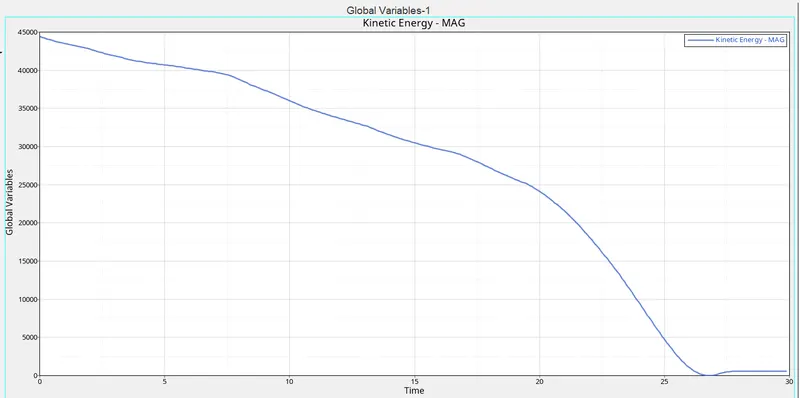
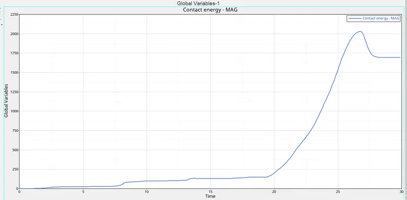
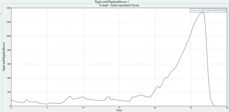
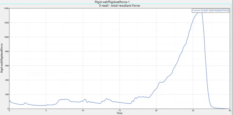
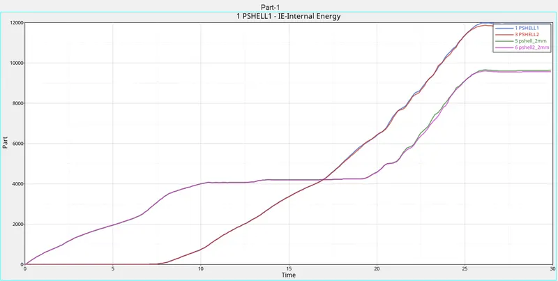
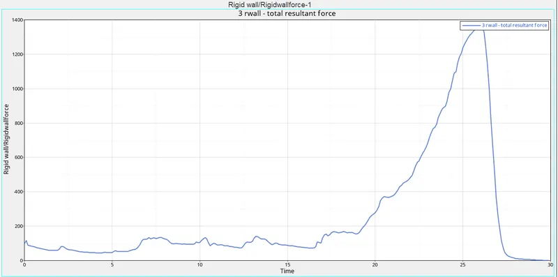
Finally, Plot RWALL forces, contact forces, internal energy, and Create TH/PART for all parts and compare results for all cases.
BUMPER MODEL;
Initially open the HyperWorks and click on the file >open >model and click on the bumper file.
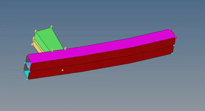
After importing the model perform the meshing operation on the given model with a 6mm mesh size.

now select the surface > set the element size and mesh type > generate mesh on the surface of the bumper.
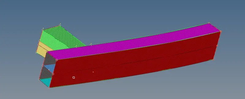
Now we have created a connection between the crash box lower and upper box with the rear bumper.
So go to connectors - seam and provide the necessary values. with a mesh size of 6mm.

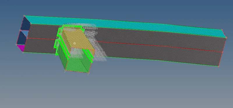
- The connections for the seam can be selected from the 1D >> Select connectors tool >> Select Spacing option >> Select the Location as Node list >> Select the Nodes >> Give the Spacing as 6 >> Select the comps in the “Connect what” area >> Give the Tolerance as 6 >> Give the Type as spring >> Click Create.
- The Connections are given at different locations where the 2 surfaces are placed parallel to each near and therefore, connection can be made.
INTRODUCTION TO INTERFACE/CONTACT MODELING;
The explicit analysis method efficiently solves complex dynamic contact problems(boundary condition nonlinearity).
Accurate modeling of contact interfaces is essential to correctly capture contact interaction between bodies. RADIOSS has a large number of contact types suitable for many applications.
In RADIOSS an interface is created by defining the master segment and slave node set. The master segment can be parts components, elements, contact surface, node surface sets, and slave entities can be parts components and node sets.
Master segments are rigid bodies and slaves are which we can analyze the stresses formations and results in the overview on them.
The contact algorithm will check every time step for potential penetration of a slave node through a master segment.
If penetration is detected the contact is treated with either a Penalty or Lagrange multiplier method.
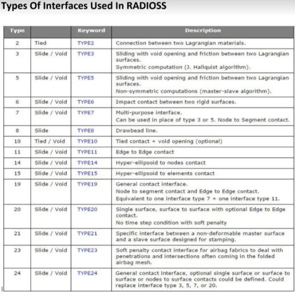
TYPE11, variable stiffness, edge to edge contact
TYPE7, variable stiffness, node to surface contact
TYPE24, linear stiffness, node to surface, and surface to surface contact
Penalty method
Interfaces using the penalty method are based on master/slave treatment.
Contact can only occur between a set of slave nodes and a set of master segments.
Master segments are defined depending on the type of element they lie on. If it is a 3-node or a 4-node shell, the segment is the surface of the element.
If it is a solid element, the segment is defined as a face. Finally, if it is a 2D solid element (quad), the segment is aside.
A gap distance is defined to determine whether or not a node is in contact with a segment.
Spring elements that generate resistive forces as a function of penetration are created between the slave node and its projection.
The spring stiffness is automatically computed according to the material and property of both the master segment and slave node.
The time step may be affected by the interface stiffness.
During the penetration, as spring is connected to the slave node, the spring stiffness must be added to the overall stiffness acting on the node (stiffness from all elements connected to this node).
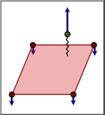
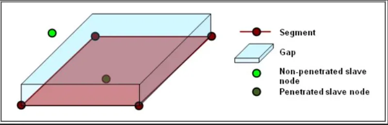
The nodal time step must be reduced to account for the spring stiffness. Contact ends when the penetrated node is completely pushed out of the gap. Therefore, the elastic spring and the reaction forces are removed.
Lagrange Multiplier Method (/LAGMUL and /INTER/LAGMUL)
The Lagrange Multiplier method is purely mathematical and does not require physical elements (springs) to model contact.
A nonlinear system of equations is solved to account for contact conditions.
Therefore, there is no time step collapse due to high interface stiffness, but it takes more CPU time to do one cycle as new equations need to be solved by a nonlinear solver.
The method has the advantage to stop slave nodes at the contact surface (the contact condition is precisely satisfied);
however, the friction cannot be computed.
Variations of interfaces
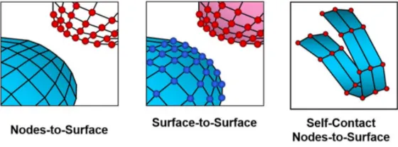
Important Interface Parameters
Igap; Determines how the size of the gap is calculated
Gapmin; Minimum gap for activation of the interface
Inacti; Action to take if initial penetrations exist
Istf; Affects how the stiffness of the interface is calculated
Iform; Friction formulation
Stmin; Minimum stiffness to use in the interface
Idel; Update For Deleted Elements Due To Failure
The recommended contact parameters for interface Type 7:
• Istf=4
• Igap=2
• Fscale_Gap=0.8
• INACTI=6
• Gap_min=0.5
• Fric = 0.1
• Iform=2
Interface Type 7: Some Gap Definitions
• gm: master element gap:
gm = t/2, t is the thickness of the master element for shell elements
gm = 0 for brick elements
• gs: slave node gap:
gs = 0 if the slave node is not connected to any element or is only connected to brick or spring elements
gs = t/2, t is the largest thickness of the shell elements connected to the slave node
gs for truss and beam elements, with S being the cross-section of the element.
• If the slave node is connected to multiple shells and/or beams or trusses, the largest computed slave gap is used.
Type 11;
• This interface simulates impact between edge to Edge or lines. A line can be
a beam or truss element or a shell edge or spring elements.
In association with interface TYPE7, interface TYPE11 solves the locking cases
• Defined by identifying master and slave lines (edges)
• Impacts occur between a master and a slave line.
A slave line can impact on one or more master lines. A line can belong to the master and the slave side.This allows selfimpact.
• Works similar to Type 7 in terms of Penalty formulation, Gap definition and
Search method.
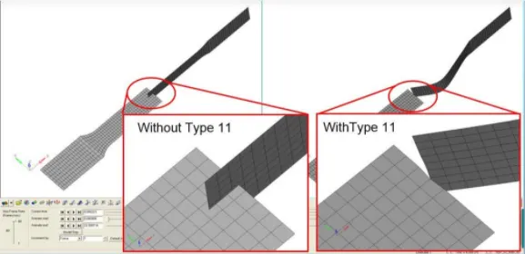
- Run the crash tube model as it is.
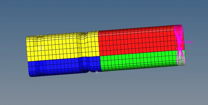
- To open the rad file, Go to the Import section in the Standard toolbar >> Select Import from Solver Deck >> Select the File to import (File Name: Crush_tube_0000.rad) >> Click Import.
- The Model is imported.
- After the Model is imported, The Simulation needs to be performed in this crush tube case.
- To simulate the model, Go to the Analysis Panel, Select the Radios Option >> Select the area to save the file on the data.
- Save the File in a separate folder naming Crush tube case 1 as it will be easy to check the models >> Check include collectors box >> In the options tab, type “-nt 4” >> Click Radios.
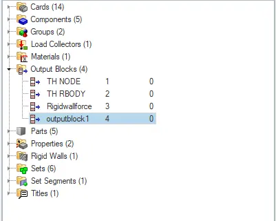
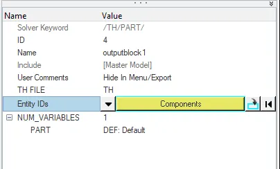
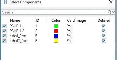
In order to create the THPART we have to click on the output Blocks and create the TH PART, in entity id instead of nodes keep components and select all four components and click on ok. Then the TH part is created.
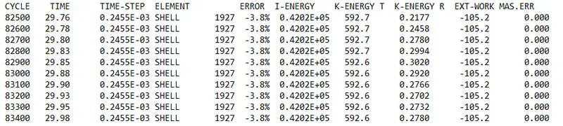
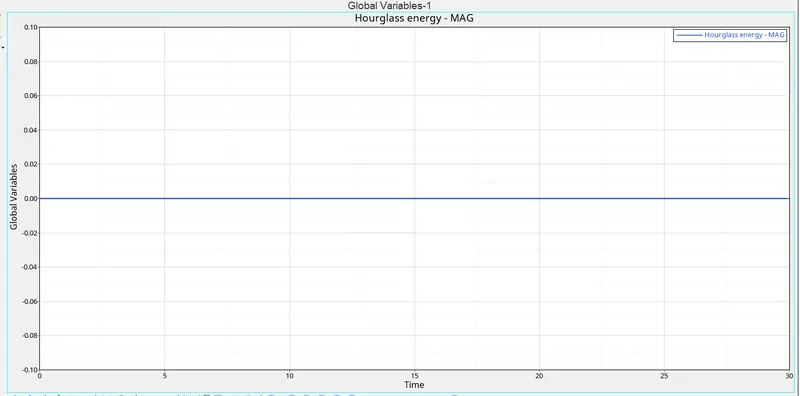
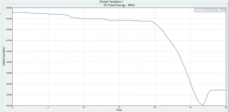
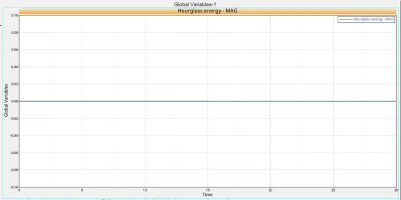
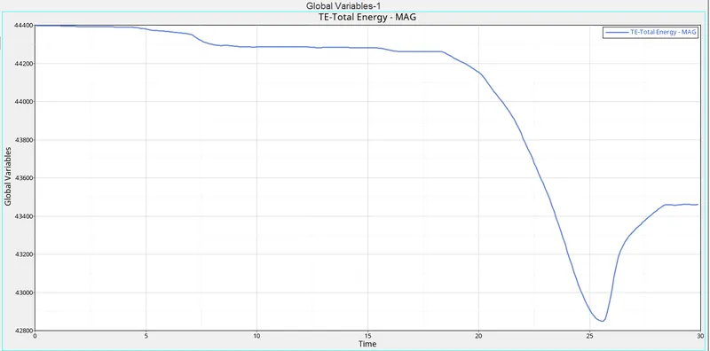
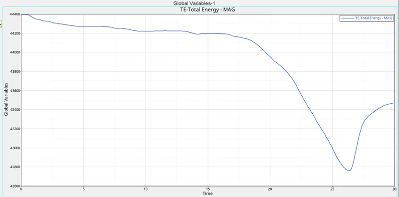
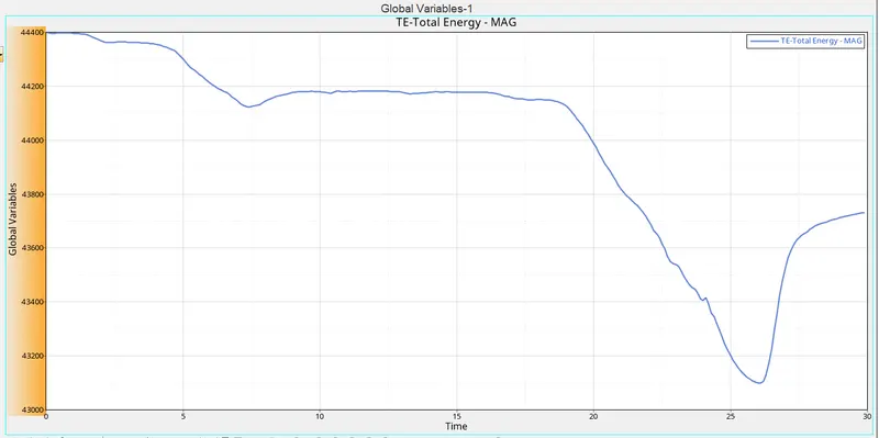
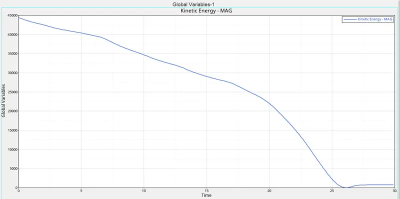
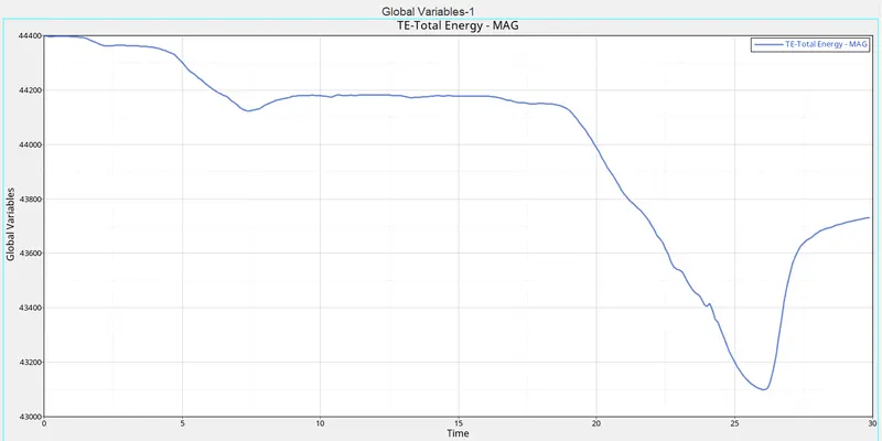
Check the mass and energy errors in the out file ,which we can see the below figures that we conclude energy and mass errors are in their limit are not.
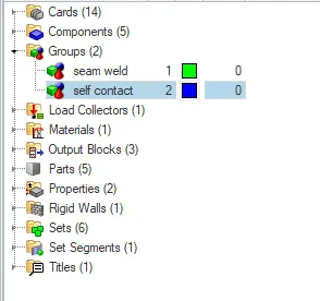
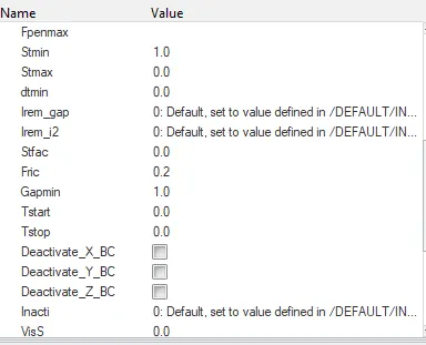
In this case we use only the type7 as node to surface contact /interface in the self contact and run the rad file without any modifications.
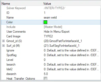
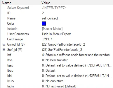
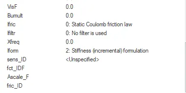
In case1 we use type 7 as a card image and run the crush tube without any changes in the parameters.
2.Change the Inacti=6 and run.
- In this case, the Inacti value should be changed.
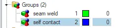
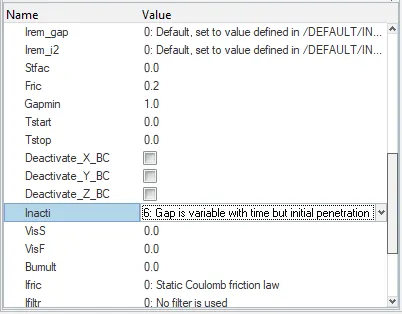
- To change the value, go to the model browser in the Tab Area >> Click Group tab >> Select Self Contact Option.
- In the value entity bar, the Inacti value is displayed as 0. >> Change the Inacti value to 6.
- To simulate the model, Go to the Analysis Panel, Select the Radioss Option >> Select the area to save the file and Click Radioss.
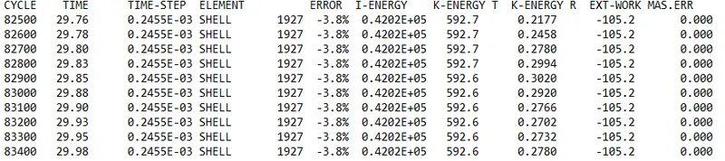
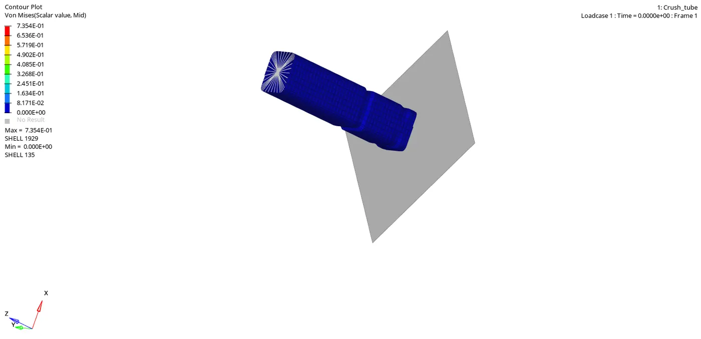
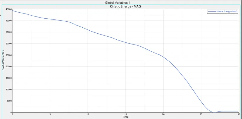
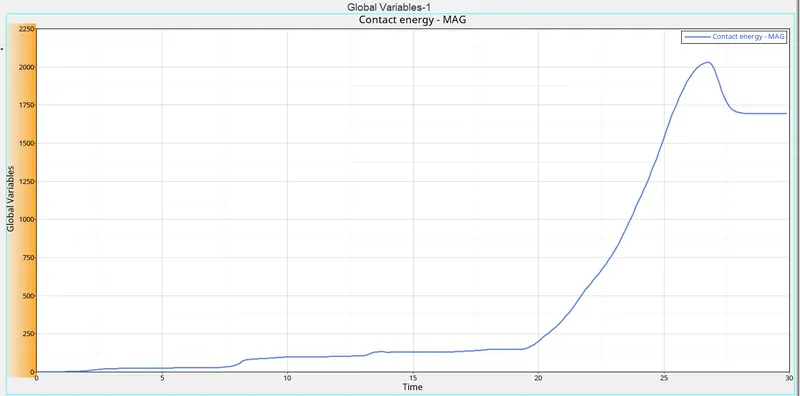
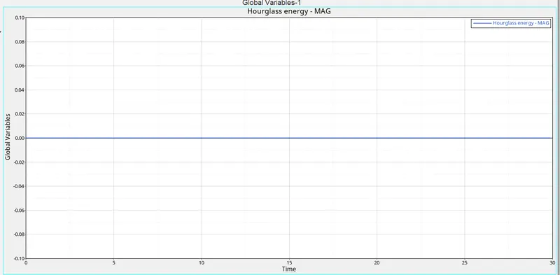
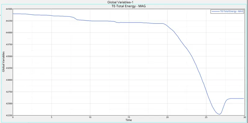
Check the mass and energy errors in the out file, which we can see in the below figures that we conclude energy and mass errors are in their limit are not.
3.Create the type 11 contact and run.
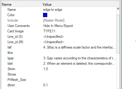
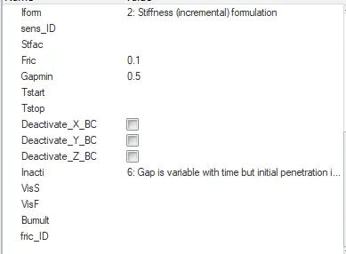
- To create a New Type interface, Right-click on the Groups tab in the Model Browser >> Name the New group as “Type 11” >> Give the Values of interfaces.
- Igap=3
- Gap min=0.5
- inacti=6
- Istiff=4
- Idel=2
- Iform=2
- stmin=1000n/mm or 1kn/mm.
- The new interface card is prepared.
- To simulate the model, Go to the Analysis Panel, Select the Radios Option >> Select the area to save the file >> Click Radios.
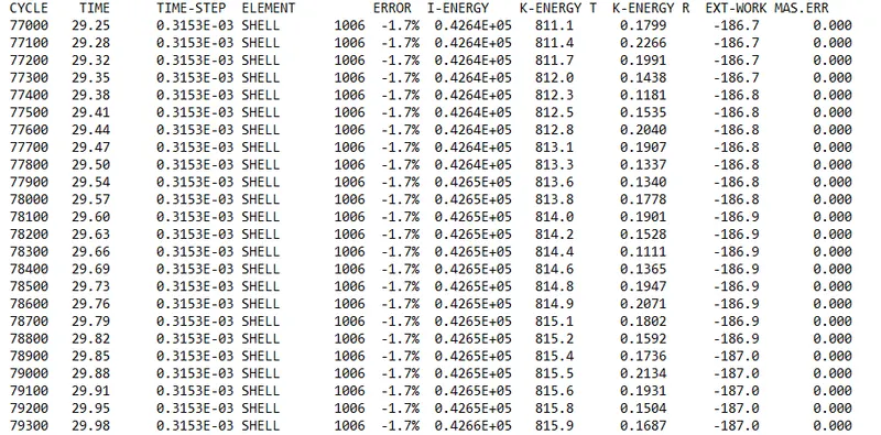
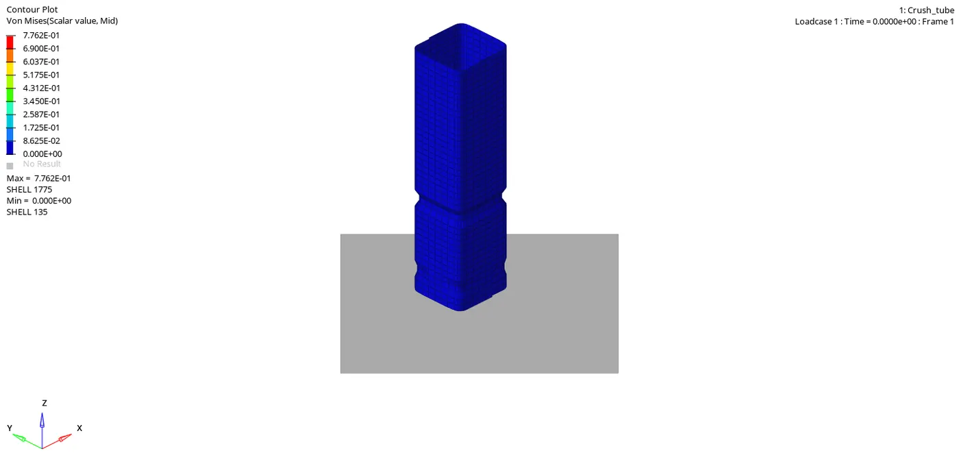
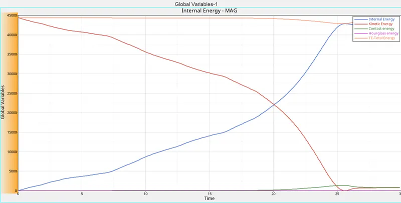
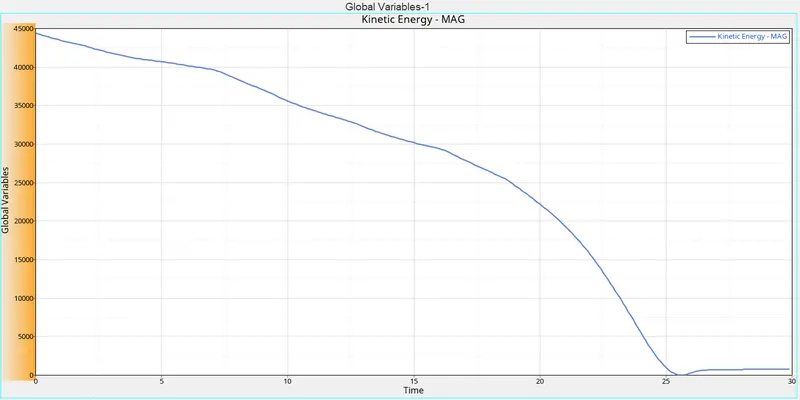
Check the mass and energy errors in the out file, which we can see in the below figures that we conclude energy and mass errors are in their limit are not.
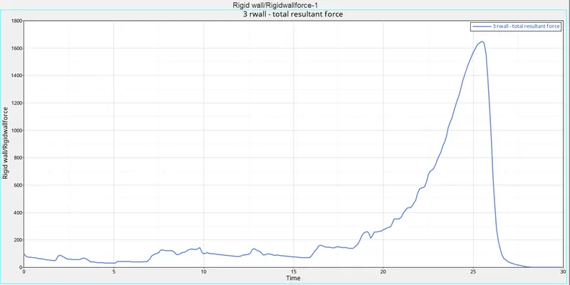
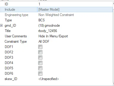
4.Remove both notches and remove boundary condition on rigid body node then run.
- In this case, the notch needs to be deleted and make into a plane mesh.
- To avoid notches in the surfaces we use the algin method, in which we align the nodes of an element in the straight.
- The Notch elements are aligned properly.
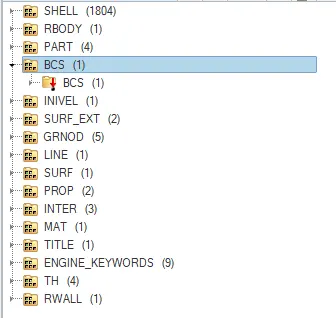
- Now to delete the Boundary conditions, Go to the Solver Deck, If the Solver deck is not visible, Go to the View tab in the Standard menu bar>> Click Browse >>Click Hyper Mesh >> Click on Solver >> The Solver Deck will be opened. Remove the degree of freedom in the BCS Entity in the Solver Deck.
- To simulate the model, Go to the Analysis Panel, Select the Radioss Option >> Select the area to save the file >> Click Radioss.
- The Simulation is run successfully.
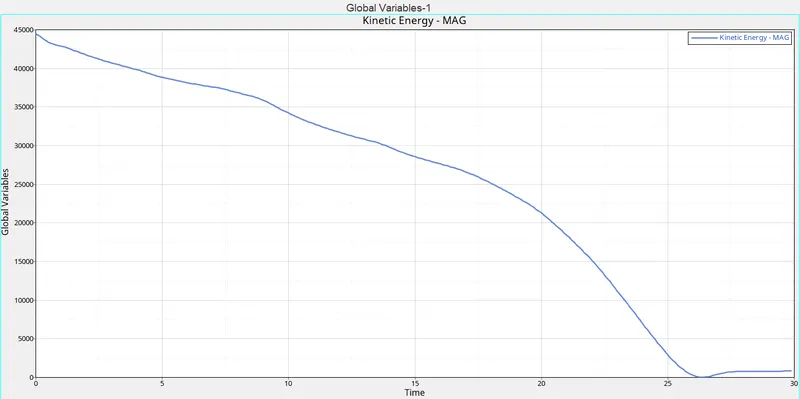
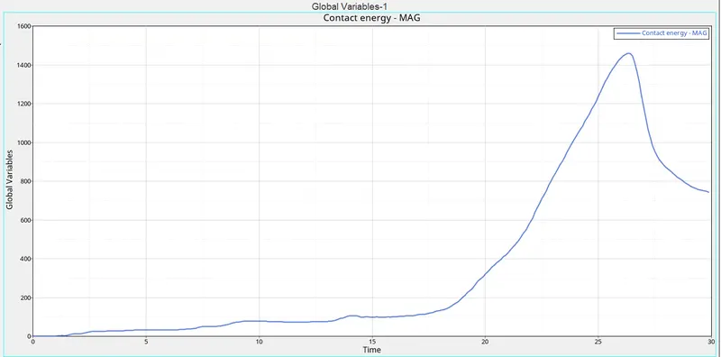
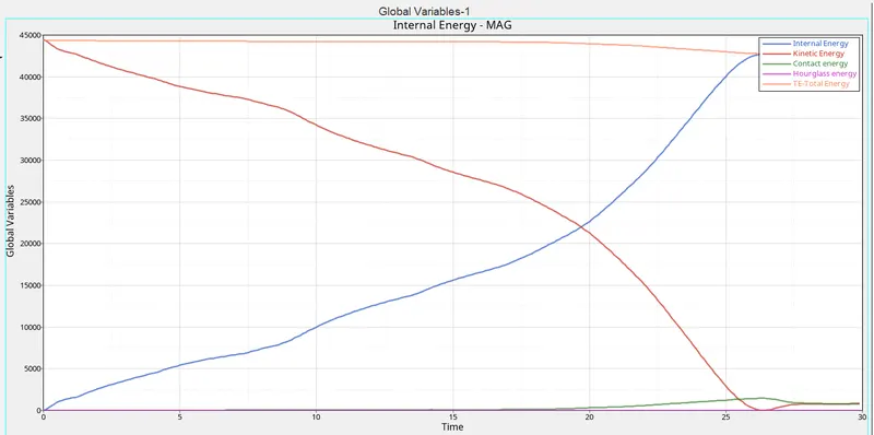
Check the mass and energy errors in the out file, which we can see in the below figures that we conclude energy and mass errors are in their limit are not.
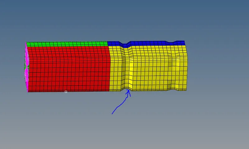
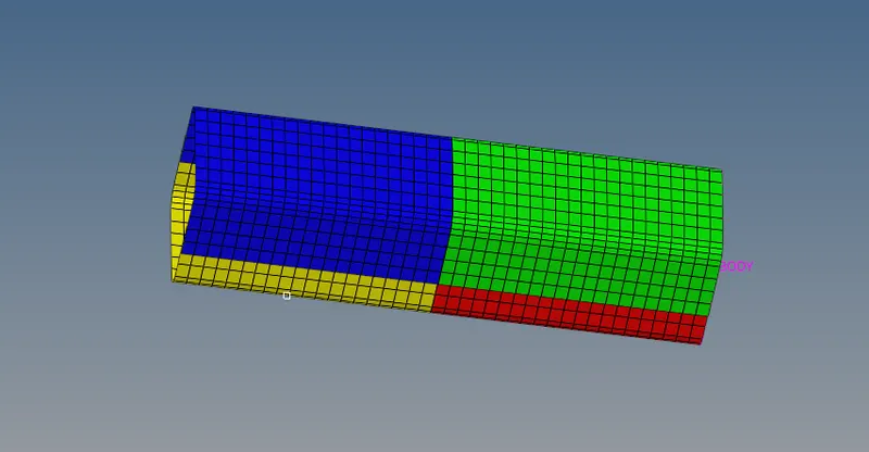
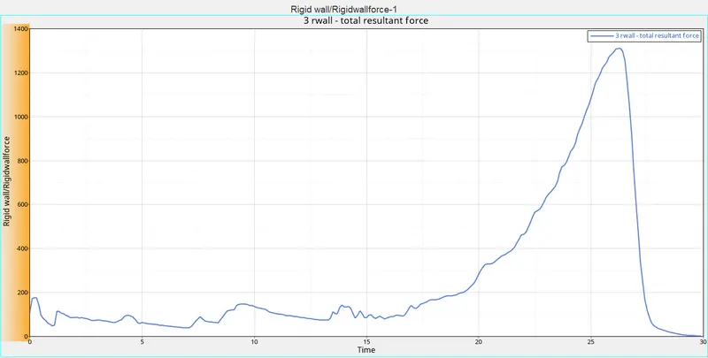
5.Create a new notch in the middle, select the whole section and run.
In this case, a new notch needs to be created and to create a notch in the plane surface, the Translate option is used.
- To Translate the elements, Go to the Tools panel, Select Translate option >> Select the Nodes to translate >> Select the Orientation of the elements (i.e. in which direction the elements should be moved)
- Give the Magnitude as 4.094 (Distance from nod to node).
- The Notch is created.
- To simulate the model, Go to the Analysis Panel, Select the Radioss Option >> Select the area to save the file >>click radioss.
- The Simulation is run successfully.
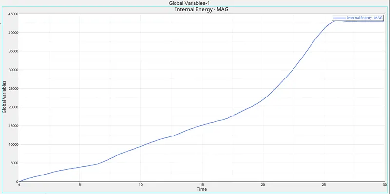
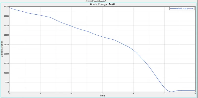
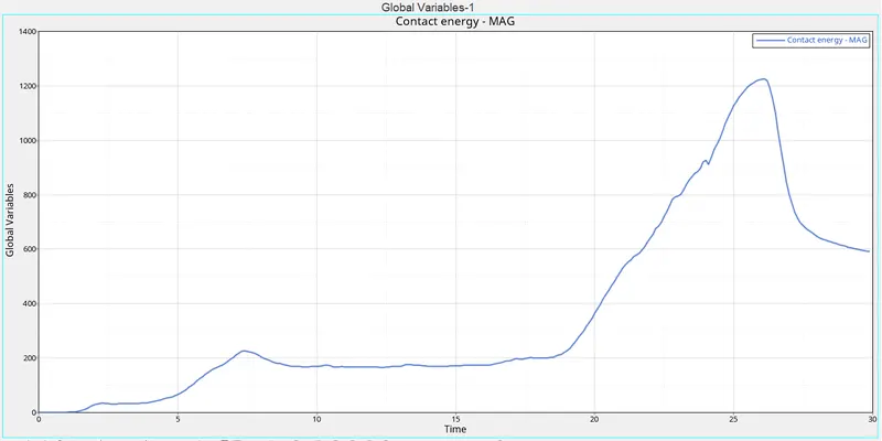
Check the mass and energy errors in the out file ,which we can see the below figures that we conclude energy and mass errors are in their limit are not.

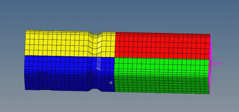
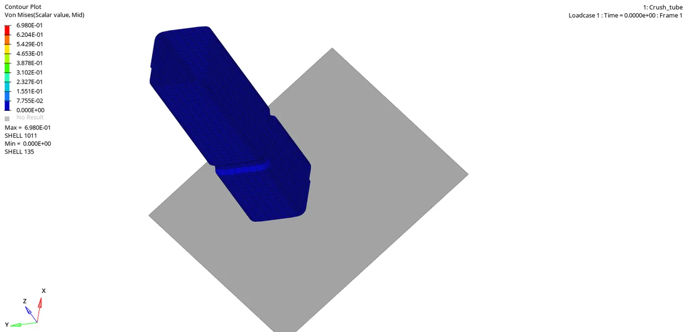
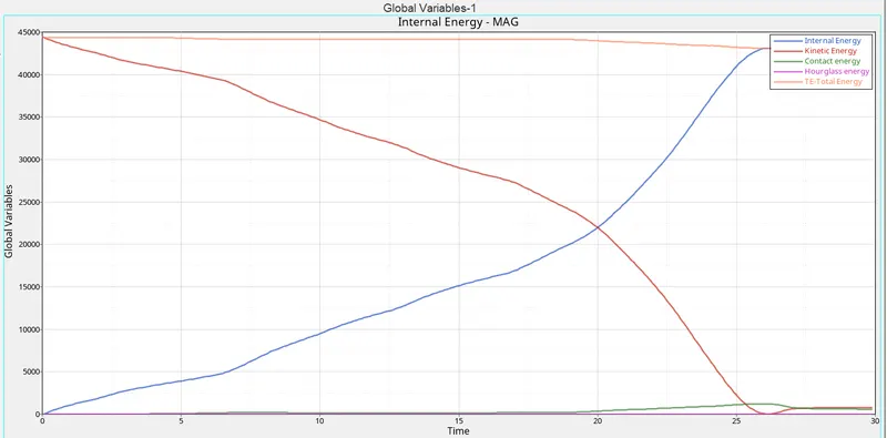
6.Create a new notch with nodes only from opposing 2 faces and run.
- In this case, a notch should be created at the same place in the opposite 2 face direction.
- Again to create a notch, the Translate option is used.
- Go to the Tools panel, Select Translate option >> Select the Nodes to translate >> Select the Orientation of the elements (i.e. in which direction the elements should be moved) >> Give the Magnitude as 4.094 (Distance from node to node).
- The Notch is created.
- To simulate the model, Go to the Analysis Panel, Select the Radios Option >> Select the area to save the file >> click radios.
- The Simulation is run successfully.
Check the mass and energy errors in the out file, which we can see in the below figures that we conclude energy and mass errors are in their limit are not.

CONCLUSION;
NOTCHES;
In mechanical engineering and material science, a notch refers to a deliberately introduced v-shaped, u-shaped, or circular defect in a planar material. In structural components, a notch causes a stress concentration which can result in the initiation and growth of fatigue cracks. Notches are used in material characterization to determine fracture mechanics-related properties such as fracture toughness and rates of fatigue crack growth.
In this sense, a notch means local stress and strain concentrator. Locations with high local stress concentration usually form critical points in mechanical structures where a static failure occurs or where a fatigue crack begins to spread.
Notches can be categorized from different criteria.
which determines the amount of energy absorbed by a material during fracture Absorbed energy is a measure of the material's notch toughness. It is widely used in industry since it is easy to prepare and conduct and results can be obtained quickly and cheaply. A disadvantage is that some results are only comparative.
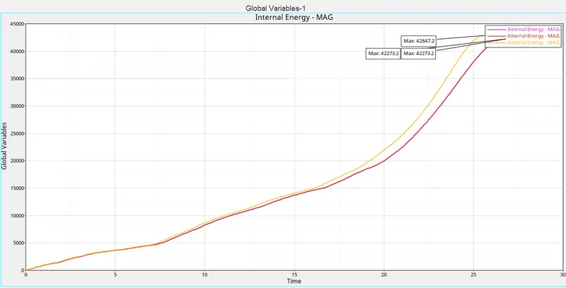
INTERNAL ENERGY
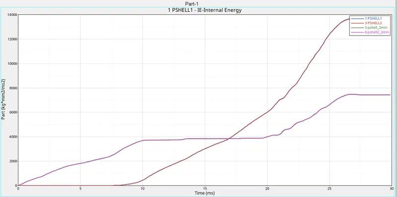
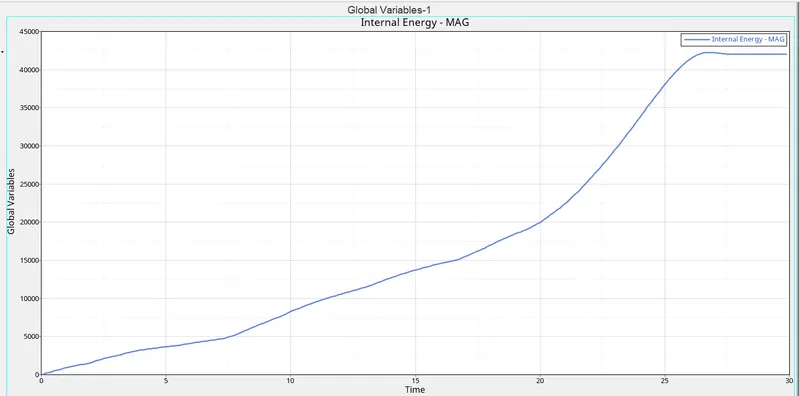
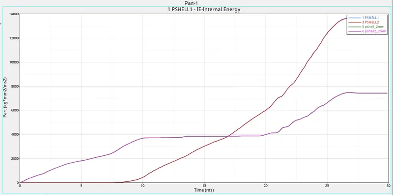
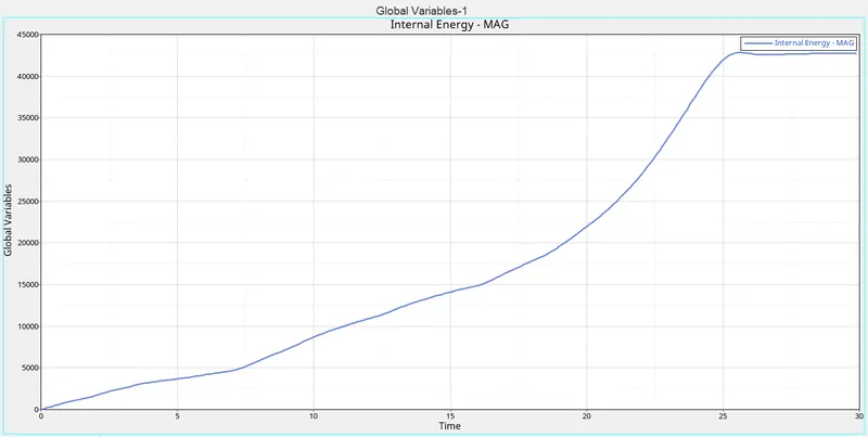
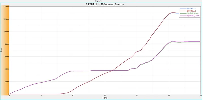
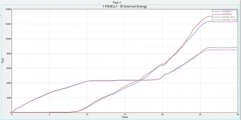
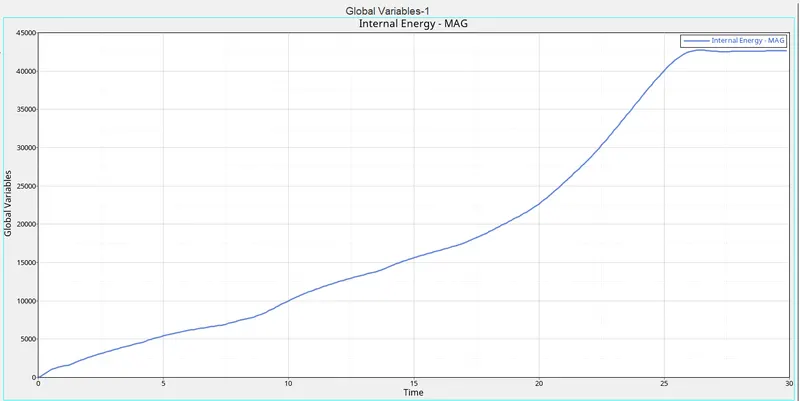
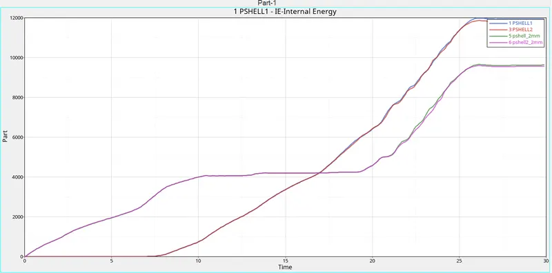
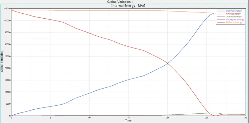
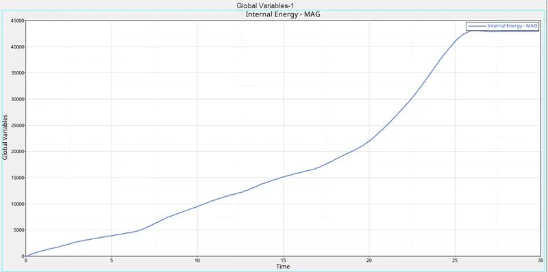
The internal energy will have more ability of the body to absorb forces when deformations occurring on them(stress acting on them), the more internal energy the more impact absorbed by the body of the system.
- As we look into the graph the internal energy is increasing with increase in impact simultaneously the deformation takes place at the notches first and directs the stress to the remaining part of the surface .
Case1,2,3
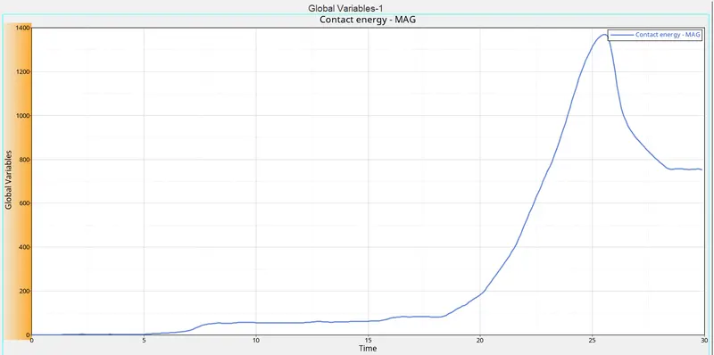
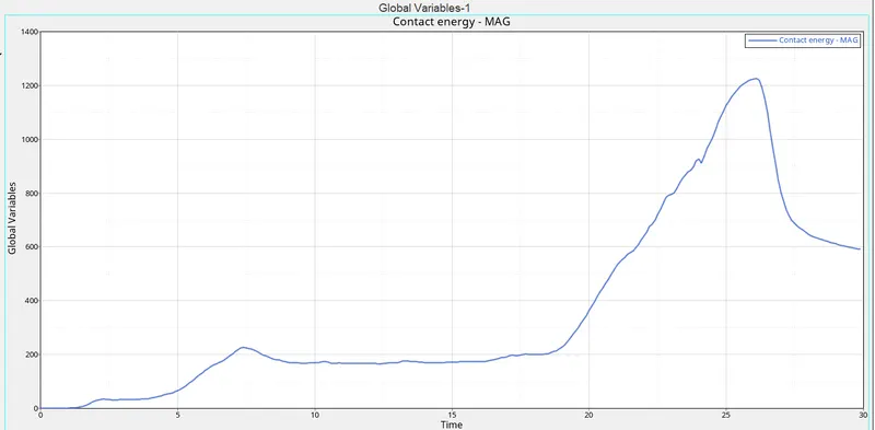
Comparing the Contact in the case 1,2,3
we have seen that contact is good at the type11 (edge to edge) case3, and the remaining cases 1 and 2 are very high.
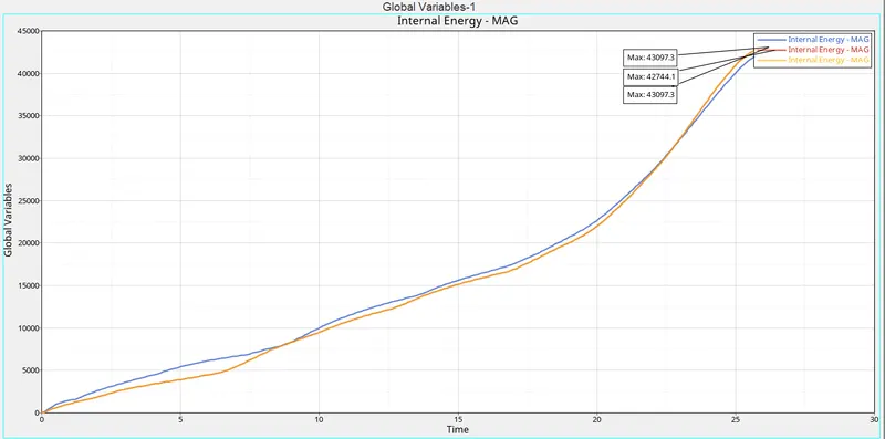
Case4,5,6;
How does the notch affect the results?
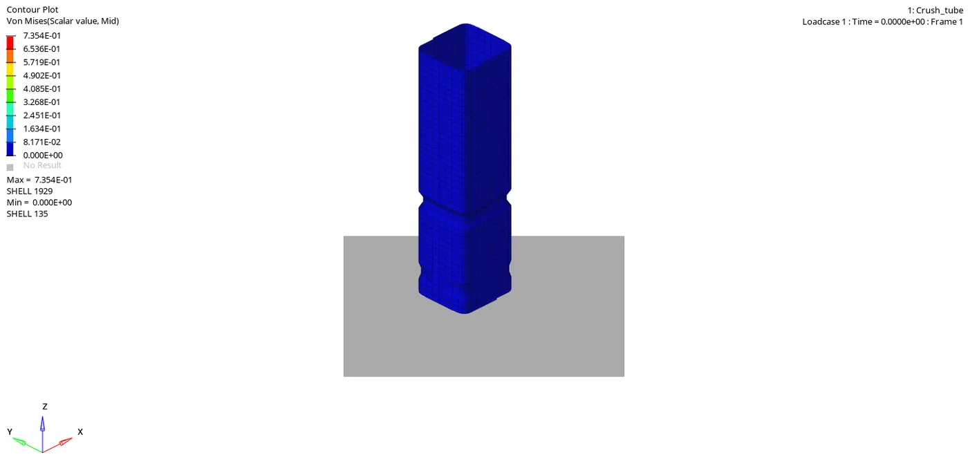
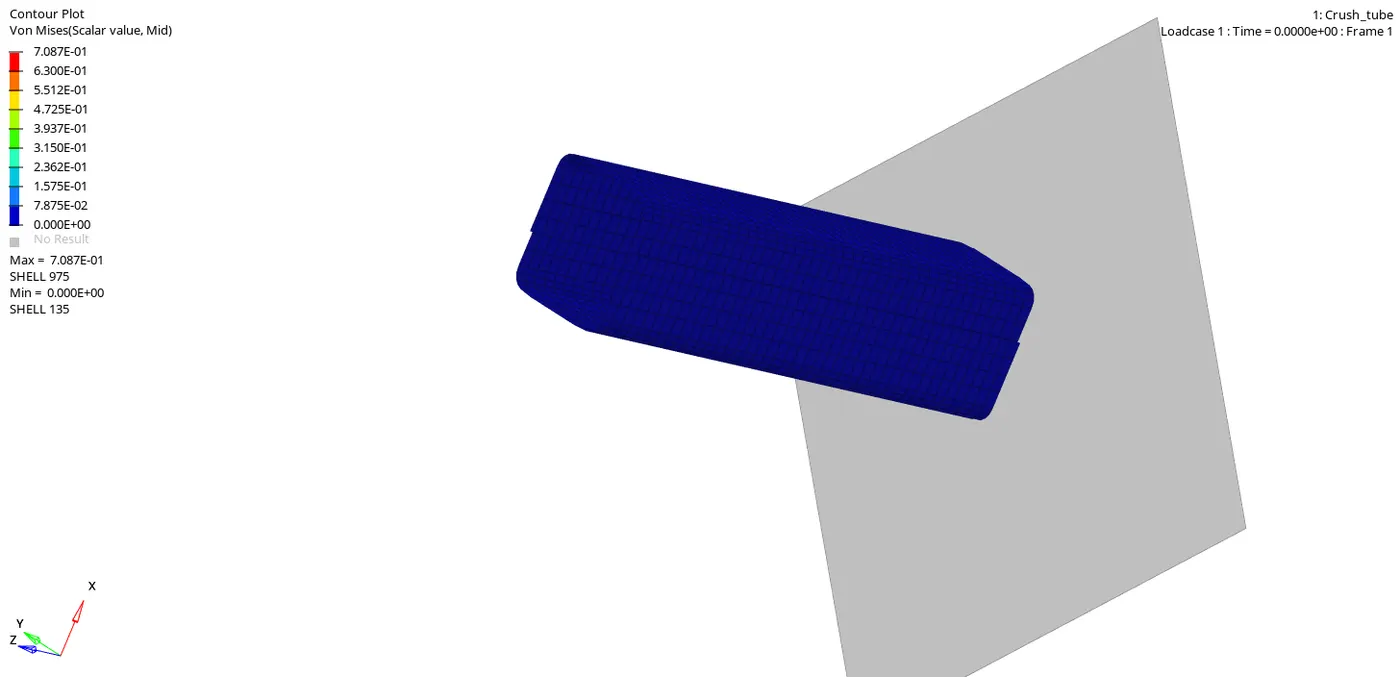
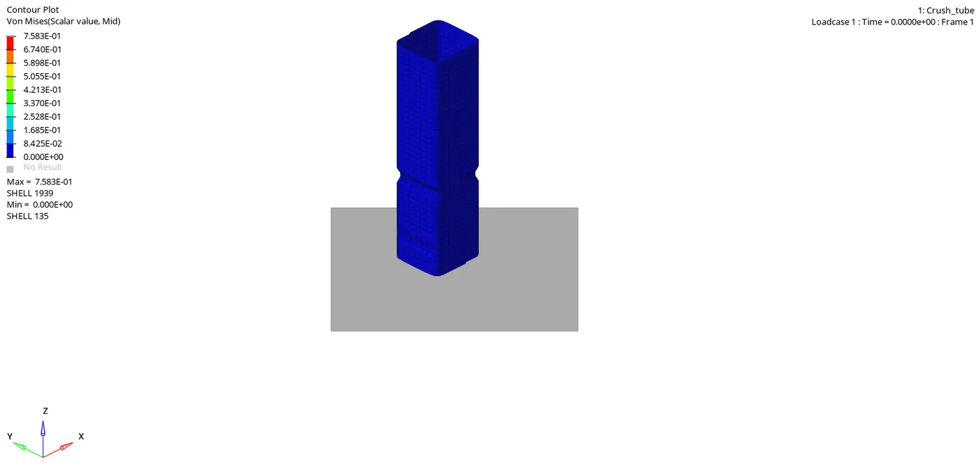
The notch areas have high stresses and deform first. In the plane surface where the notches are removed the stress levels are high. Hence, we can state that removing the notches will lead to an increase in the stress acting in the body.
In case 4 removal of the notches will show the stress concentration will be more.
changes occur in the Internal Energies?
The change in the internal energy is due to the notch. With the removal of the notch, the internal energy decreases in the case4(notches deleted), which we can see clearly below table compare to the case5 and case6(notches created), the internal energy increases and have more absorbing capacity compare to the case4
| no | Cases | energy error | mass error | Von Moises stress | hourglass | Internal energy | Contact maximum | Contact minimum | Rigid wall forces |
| 1 | Run the model as it is | -3.8 |
0.000 |
7.354E-01 | 0 | 42273.2 | 2001 | 1650 | 1320 |
| 2 | change inacti 6 and run the simulation | -3.8 | 0.000 | 7.354E-01 | 0 | 42273.2 | 2001 | 1650 | 1320 |
| 3 | create type11 contact and run the model | -1.7 | 0.000 | 7.762E-01 | 0 | 42847.2 | 1380 | 780 | 1620 |
| 4 | Remove both notches and boundary conditions | -1.7 | 0.000 | 7.807E-01 | 0 | 42744.1 | 1420 | 780 | 1300 |
| 5 | Create a notch in the middle | -1.3 | 0.000 | 6.980E-01 | 0 | 43097.3 | 1220 | 600 | 1340 |
| 6 | Create the new notches in opposite two faces | -1.3 | 0.000 | 7.583E-01 | 0 | 43097.3 | 1220 | 600 | 1320 |