Assignment 5-RADIOSS Interfaces & Study of Effect of Notches Challenge
AIM: To create the mesh for bumper assembly using 6mm mesh size.
PROCEDURE:
- Geometry modification was done using Surface Edit and Edge Edit option under Geometry Tab.
- Mesh option was utilised using the F12 key and each component meshed individually.
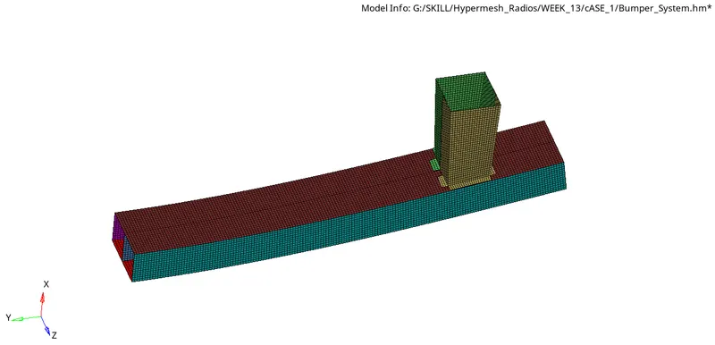
Case 1: Run the crash tube model as it is.
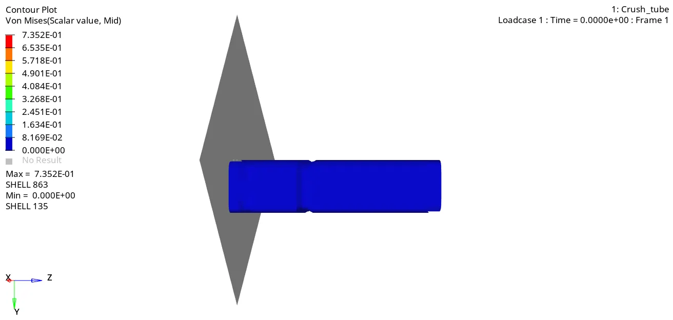
Energy Plot Comparison
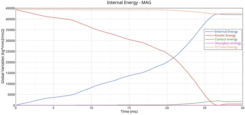
From the results of the simulation, it was observed that there was a 3.8% energy error encountered in the crash simulation. The energy plot depicts that through the simulation, the total energy of the system was conserved but in the later stage where complete compression of the sample took place, resulting in some energy losses.
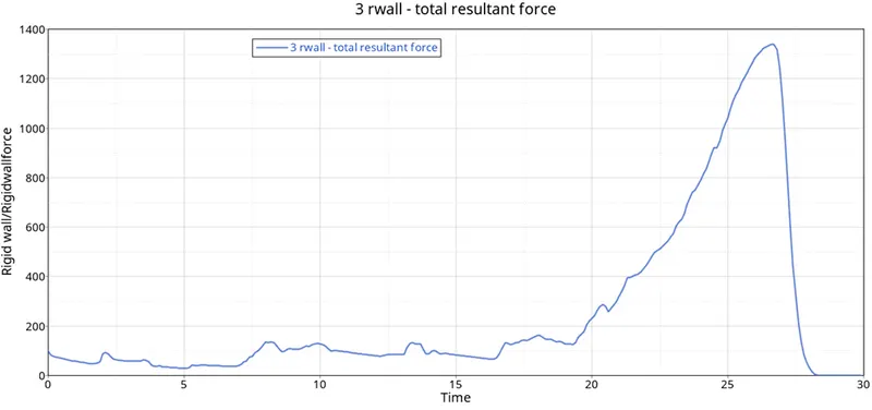
Total rigid wall force was plotted and a peak force of about 1338KN was observed.
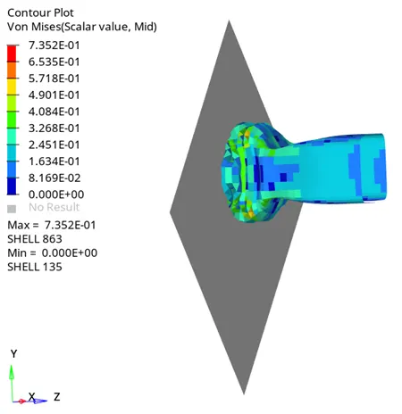
Case 2: Change the Inacti=6 and run.
Energy Plot Comparison
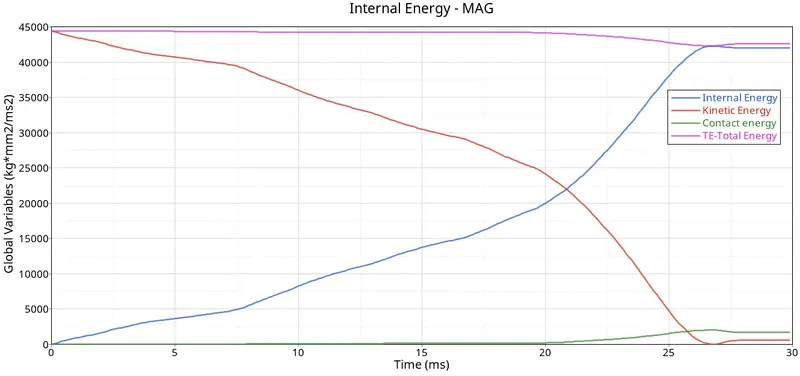
From the results of the simulation, it was observed that there was a 3.8% energy error encountered in the crash simulation. The energy plot depicts that through the simulation, the total energy of the system was conserved but in the later stage where complete compression of the sample took place, resulting in some energy losses.
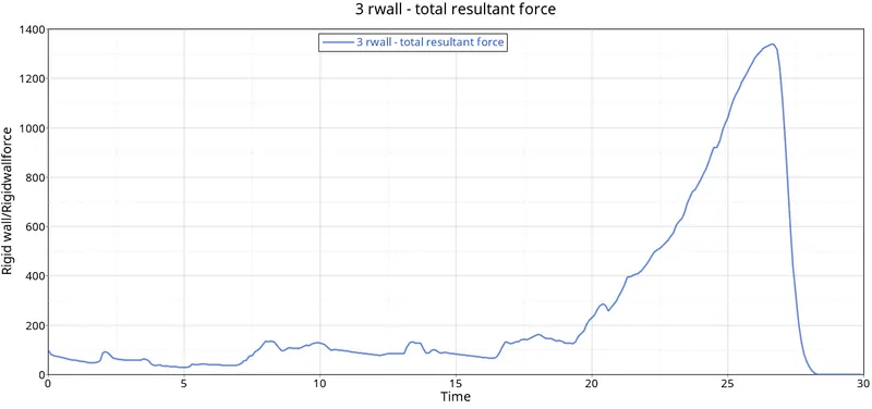
Total rigid wall force was plotted and a peak force of about 1338KN was observed.
Case 3: Create the type 11 contact and run.
There are situations where type 7 contact cannot encounter the edge in case of edges crossing, thus there is a need for contact type 11 that will encounter the edge contacts in the simulation.
Energy Plot Comparison
From the results of the simulation, it was observed that there was a 3.8% energy error encountered in the crash simulation. The energy plot depicts that through the simulation, the total energy of the system was conserved but in the later stage where complete compression of the sample took place, resulting in some energy losses.
Total rigid wall force was plotted and a peak force of about 1338KN was observed.
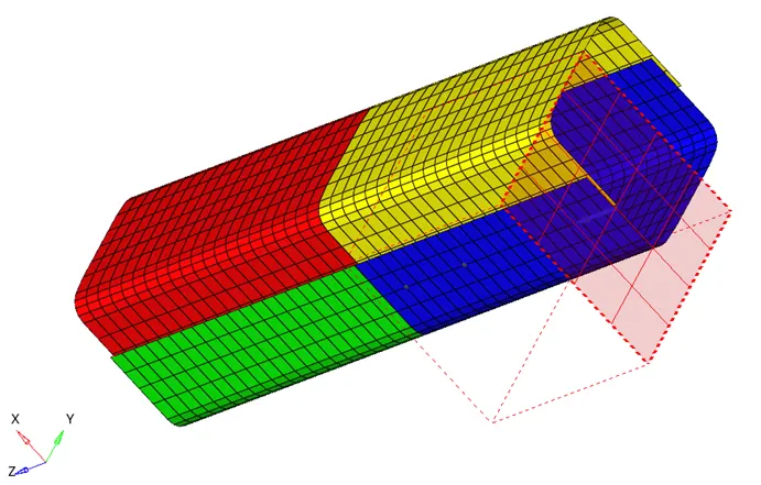
Case 4: Remove both notches and remove boundary condition on rigid body node then run.
Procedure:
1. Align nodes option was used to remove the notch from the geometry.
2. The boundary conditions were removed, where they constrained along translational and rotational DOFs was removed.
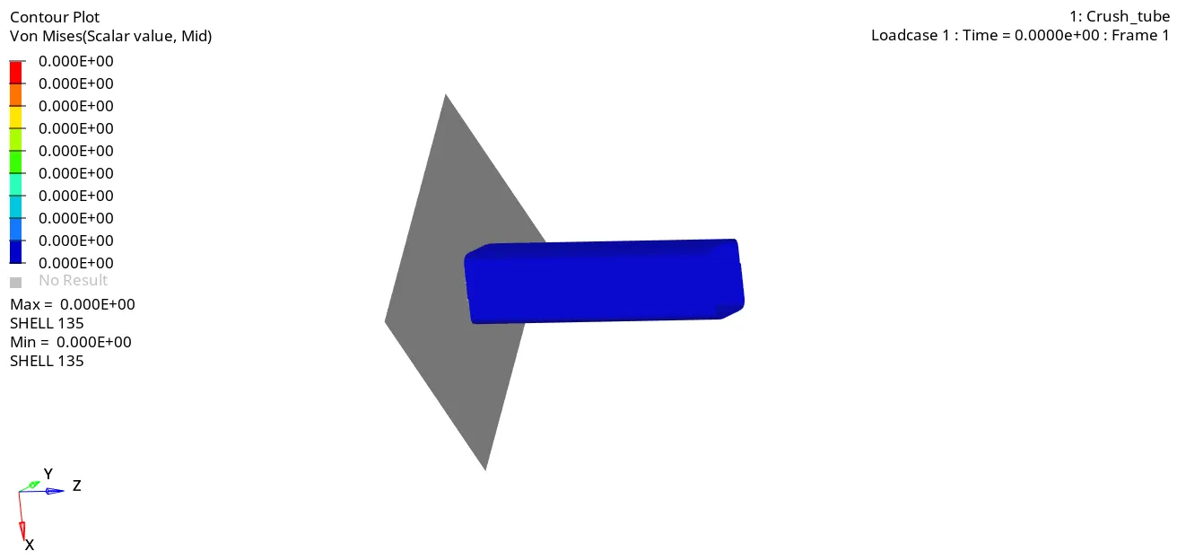
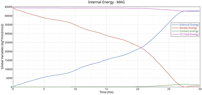
From the results of the simulation, it was observed that there was a 3% energy error encountered in the crash simulation. The energy plot depicts that through the simulation, the total energy of the system was conserved but in the later stage where complete compression of the sample took place, resulting in some energy losses.
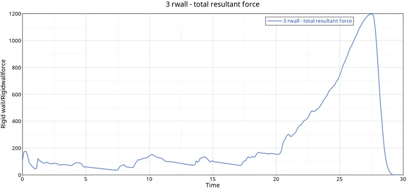
Total rigid wall force was plotted and a peak force of about 1200KN was observed.
Case 5: Create a new notch in the middle, select the whole section and run.
Procedure:
1. Using the Translate option, a notch of 2mm depth at the centre of the geometry was created.
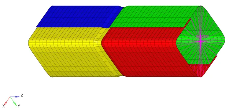
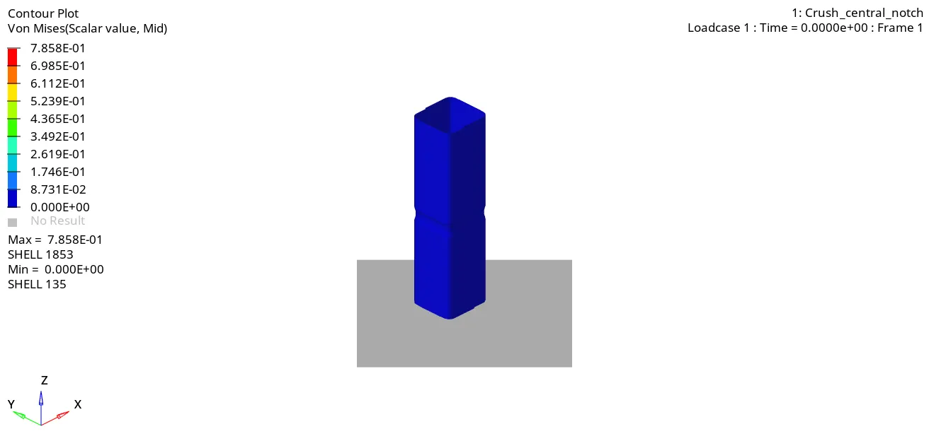
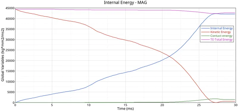
From the results of the simulation, it was observed that there was a 3.3% energy error encountered in the crash simulation. The energy plot depicts that through the simulation, the total energy of the system was conserved but in the later stage where complete compression of the sample took place, resulting in some energy losses.
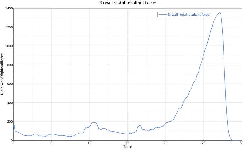
Total rigid wall force was plotted and a peak force of about 1350.40KN was observed.
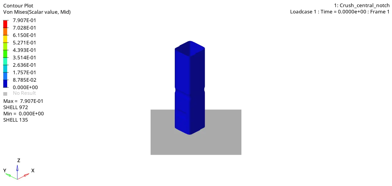
Case 6: Create a new notch with nodes only from opposing 2 faces and run.
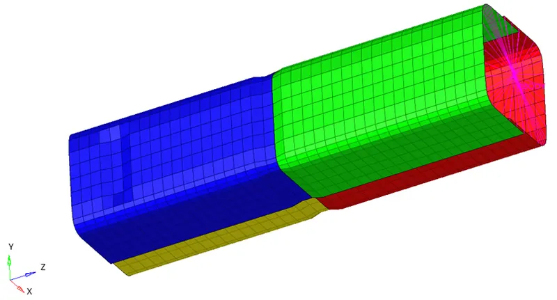
Energy Plot Comparison
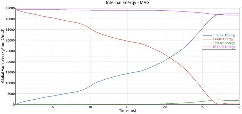
From the results of the simulation, it was observed that there was a 4.0% energy error encountered in the crash simulation. The energy plot depicts that through the simulation, the total energy of the system was conserved but in the later stage where complete compression of the sample took place, resulting in some energy losses.
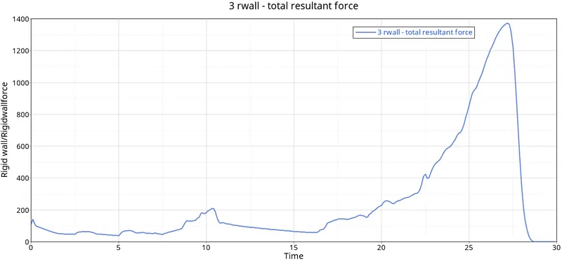
Total rigid wall force was plotted and a peak force of about 13572.12KN was observed.
CONCLUSION
- Results obtained from Case1, Case 2 and Case 3 were similar and no distinct difference in energy or rigid wall force were observed.
- The effect of the notch was evident in the samples. Central Notch leads to the failure initiation for the notched region and the maximum stress obtained is about 785MPa whereas, in the case of side-notched in the sample, the maximum stress of 790MPa was obtained.
- The energy error in all the case was within acceptable range.