Assignment 5
Objective:-
To simulate Six different cases and plot the Contact forces , Rwall forces, and Internal energy.
Compare all the six simulation results and brief on it.
Test cases:
- To run the crash model as it is without any change in its parameters.
- Change the inacti to 6 and then run the simulation.
- Create type 11 contact and run.
- Remove both the notches, remove boundary condition on rigid body and then run the simulation.
- Create a notch in the middle, and then run the simulation
- Create 2 notches in the opposite faces of the component and then run the simulation/.
Post creating all the six case radios files, plot the required graphs, and compare the von mises and comment on the result.
Import the model in the hypermesh.
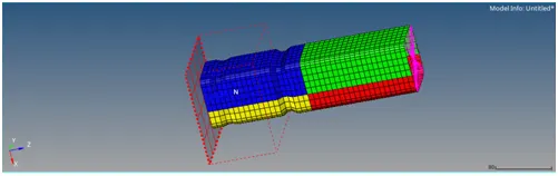
A rigid wall is their on one side of the tube. The material used is steel. The initial velocity is [-13.3m/s] in the negative z-direction.
Case 1:-
Without changing the property export the file, remember not to change any of the properties.
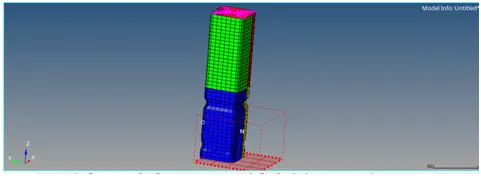
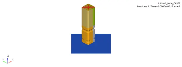
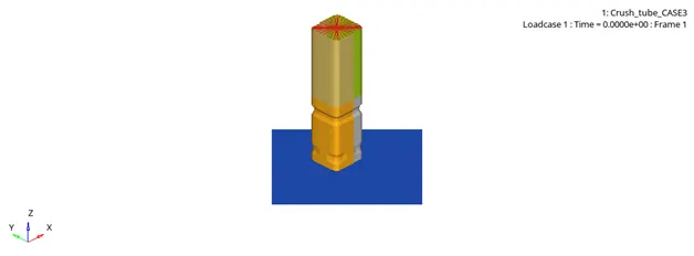
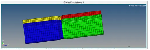
Hyperview view
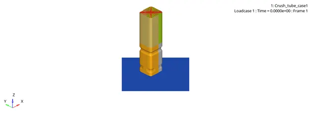
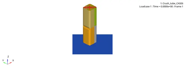
From the above it is evidemt that the buckling starts at the notch area, post notch area the component primarily ruptures at the lower region, and when the lower region is over the upper regin starts rupturing.
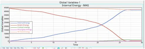
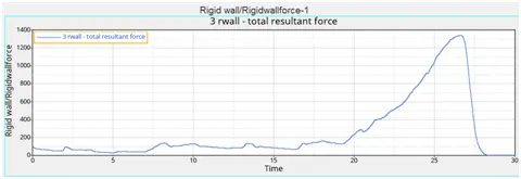
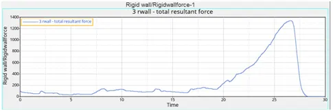
The Rwall forces maximizes after 26ms of time and goes to 1300 at max.
Case 2:-
Changing the inacti value to 6 and then running the simulation.
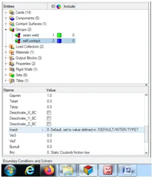
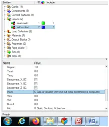
Run the simulation in hyperview and with the help of hypergraph plot the various parameters required.
Total resultant force
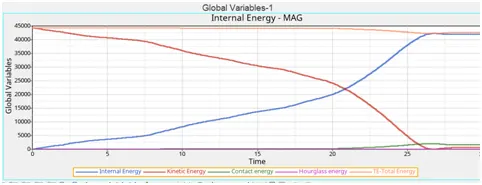
Contact energy
Inacti=6 is recommended to avoid high frequency interfaces into the surface.
As seen in the graph, the Rwall forces for this case is almost same as case – 1 and maximum of rwall force is seen at near to 1350.
Considering the contact energy, it is almost 0 and a slightly elevation is seen at 20 ms.
Case 3:-
Creating the type 11 file and then exporting the same to radioss, for further simulation.
The parameters that are set for type 11 contact are as follows:-
Istf = 4
Idel = 2
Gapmin = .45
Inacti = 6
Coulomb friction = .25
Stmin = 1
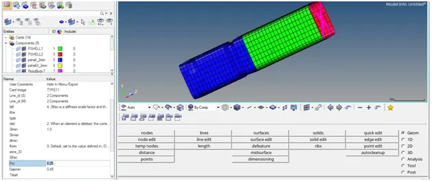
the simulation for case 3 is as follows:
plotting the rwall forces and contact energy and internal forces.
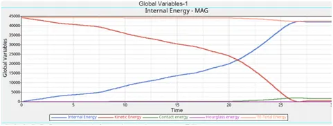
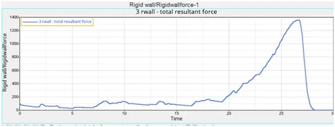
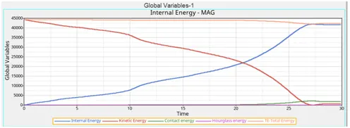
The energy plot are almost similar like in case 1 and case 2, but only a slightly change is observed due to change in contact method type i.e. type 11 co0ntact.
Case 4:-
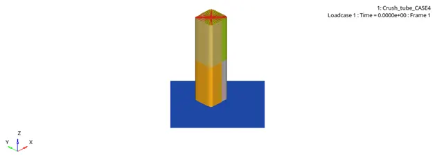
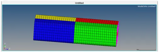
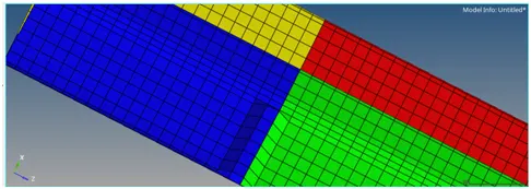
Removing the notches by using the align node command in hypermesh. Also the boundary condition is removed.
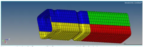
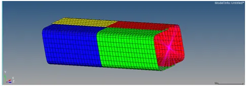
after making the changes in the model, run the simulation.
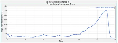
There is a slight change in rwall forces at start of the crash. In previous cases the rwall forces start at 100 but in this case it ise neaqr to 180 because of removing the notches and boundary condition.
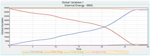
Case 5:-
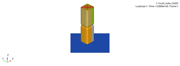
In the middle create a notch and run the simulation and comment on the difference in the graph.
Run the simulation
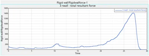
From the above graph for Rwall forces, it can be clearly seen that in this case the rwall forces maximizes to above 1400 at 26 ms.
Case 6:-
Generating notches in middle at opposite two faces only. Post notches plot graphs for contact energy and rwall forces.
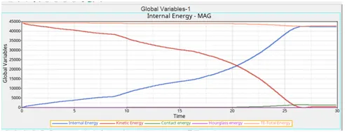
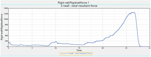
Due to reduction in notch area , it can be seen that the rwall forces is reduced in this case due to only 2 notches present as compared to the rwall force in case 5 which has the notch at all sides.
Conclusion:-
The von mises plot for all the six cases are attached below.
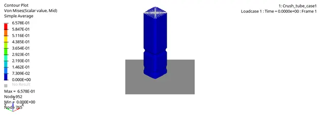
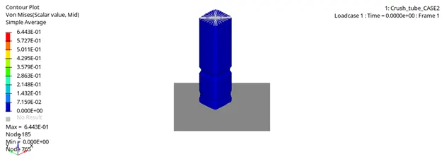
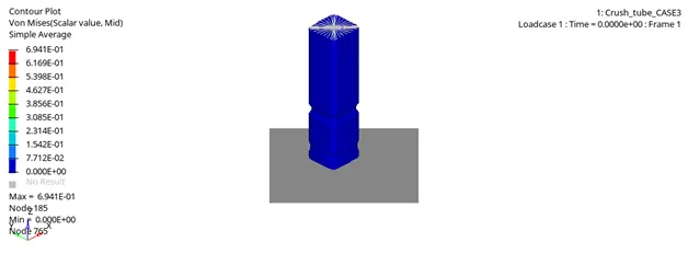
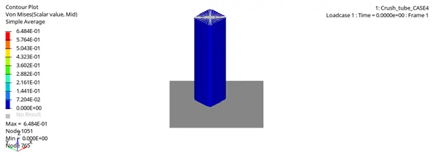
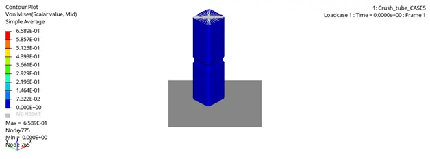
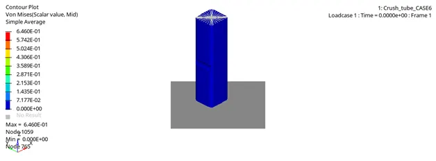
In case where both the type 7and type 11 contact methods are used it can be seen that the contacts with type 7 have more contact energy comparatively.
In all the above cases it is evident that the models with notches tend to start buckling at the notches and then it translates to the other portion of the component. As seen in case 4 in which the notch is removed the buckling starts at the bottom portion and then it gradually translates towards the upper portion.
Also it is well understood that the notches play a vital role in understanding the deformation to a component.
BUMPER SYSTEM
Objective:-
To mesh a component providsed to us with keeping the mind the quality parameters of the elements.
Import the component.
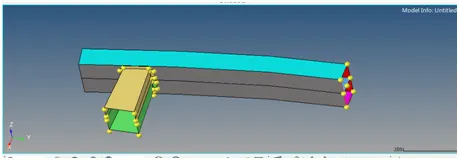
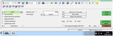
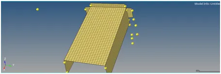
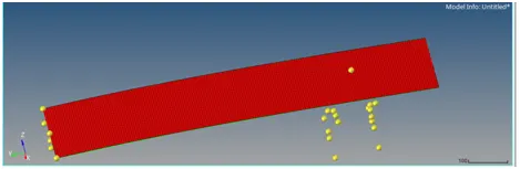
Individually meshing with mesh size 6 mm
Conclusion:-
We get a proper meshed component bumper finally. Only a half part of the bumper was with us, so reflecting the meshed half part to obtain a complete bumper component.