Crush Cube Analysis For the Study of Interfaces
Model 1:
To Create mesh For the Bumper For the given Element Size And Connect the components using suitable Connectors.
Procedure:
1. The Given component was Imported in the new Radioss file format in Hypermesh.
2. Set to the Topology Mode for viewing the errors in the model.
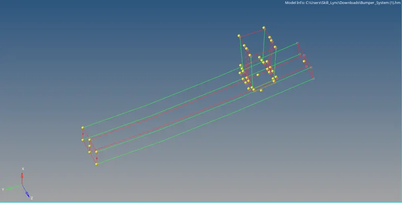
3. The Tempnodes were cleared and the Lines are deleted using delete Option F2.
4.The Surface in The middle is trimmed Using Trim with Surface Option and joined with the surface on both sides.
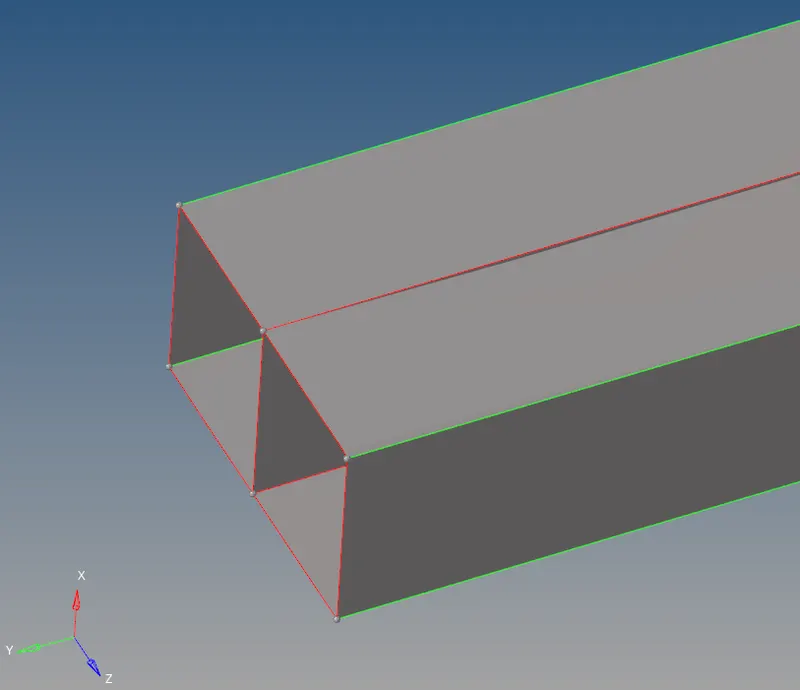
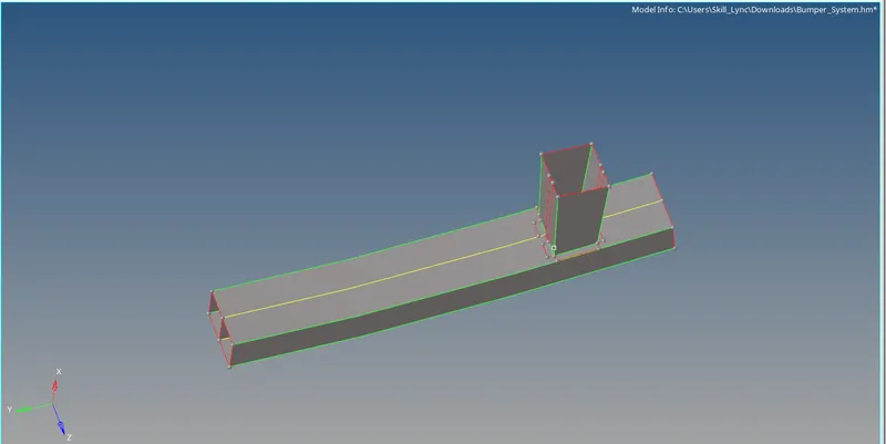
5. Another necessary Geometry cleanup was Done, like Toggling the edges Wherever necessary.
6.2D mesh was Generated over the Component With the Element Size of 6.
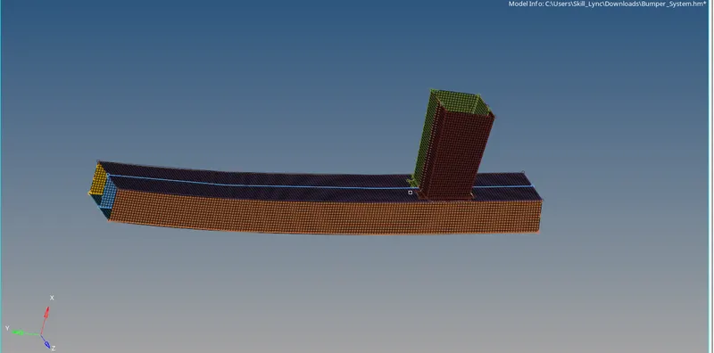
7. As the Given Component is not attached it should be Connected using Connectors.
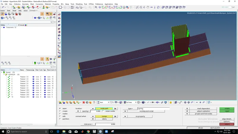
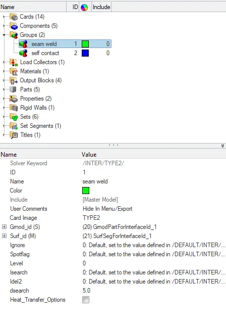
8. The connectors were Created By using the seam Option in 1D pannel.
9.1D > Connectors > Seam > Nodepath > components > create.
10. select The type of plot as Spring and Give the Required spacing and Tolerance.

11. Select The Nodes and Select The Components and choose to Create.
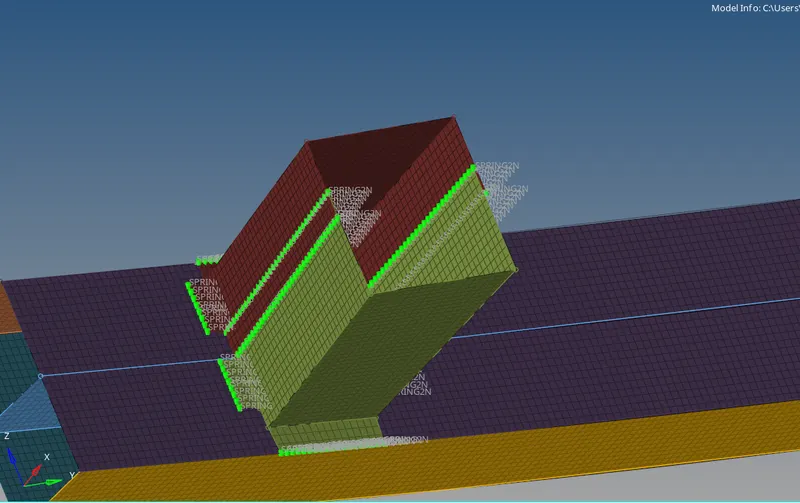
12. To Check whether the Connections are realized or not goto view > Browsers >Hypermesh > Connectors.
13.Green Colour Indicates the Connections Realized.
Comparison Of Interface With Different Properties.
CASE-1:
1.Import the given crush tube model into Hypermesh
2.no change is done to the model.
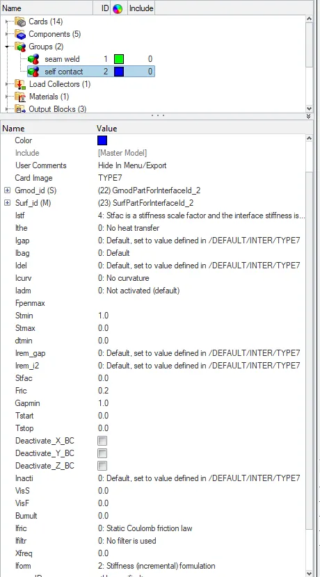
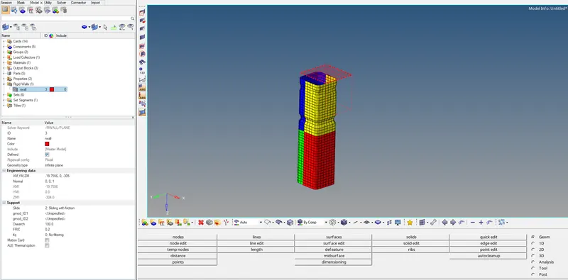
3.Note the Materials, Properties, and type of contacts used for reference
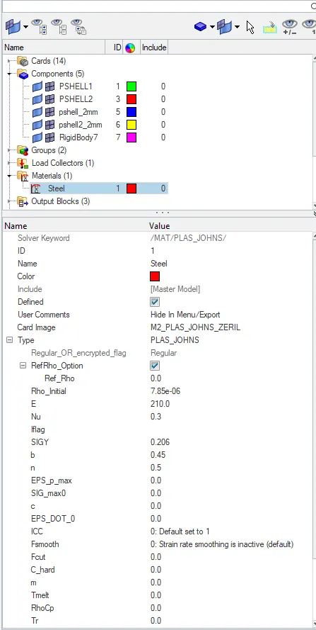
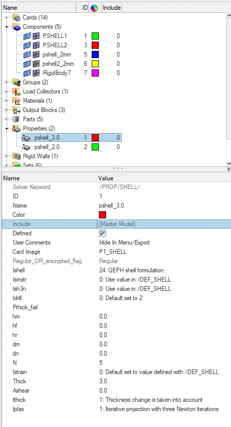
4.Click on the analysis panel in the Hypermesh.
5.Save the model in the local directory.
6.For Running The analysis: Analysis > Radioss is selected from the panel
7. The analysis runs and shows the result.
8. The energy error And mass errors are checked.
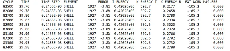
9. The energy error is -3.8 and the Mass error is 0.000 which lies within the Acceptable Conditions.
10.Click results for viewing the Analysis in Animated and Graphical Format.
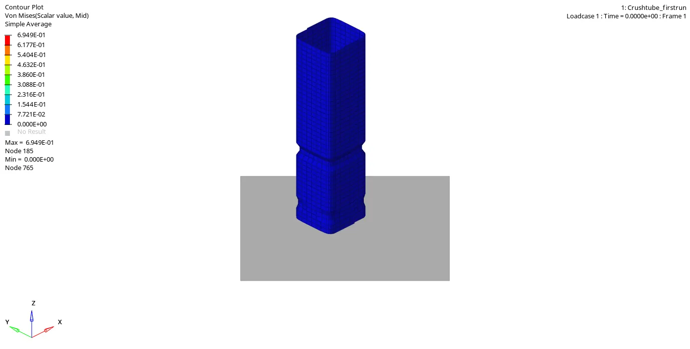
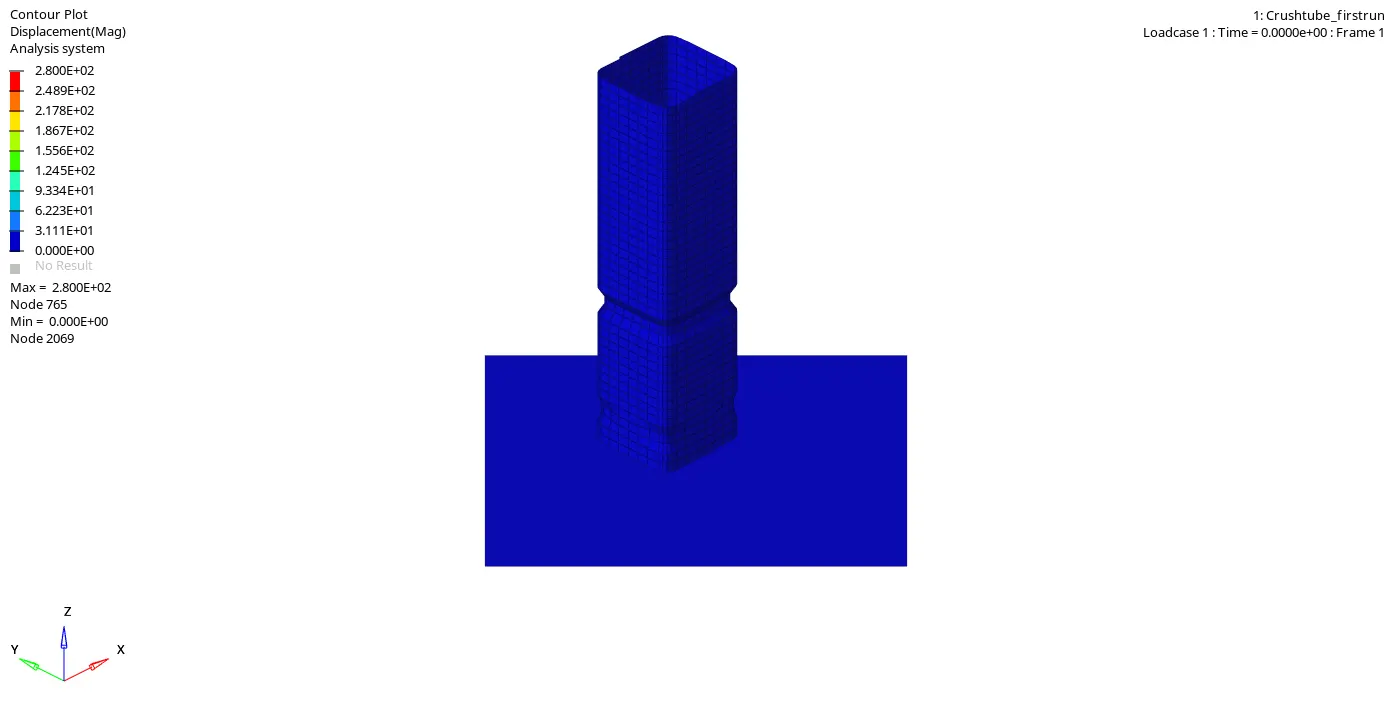
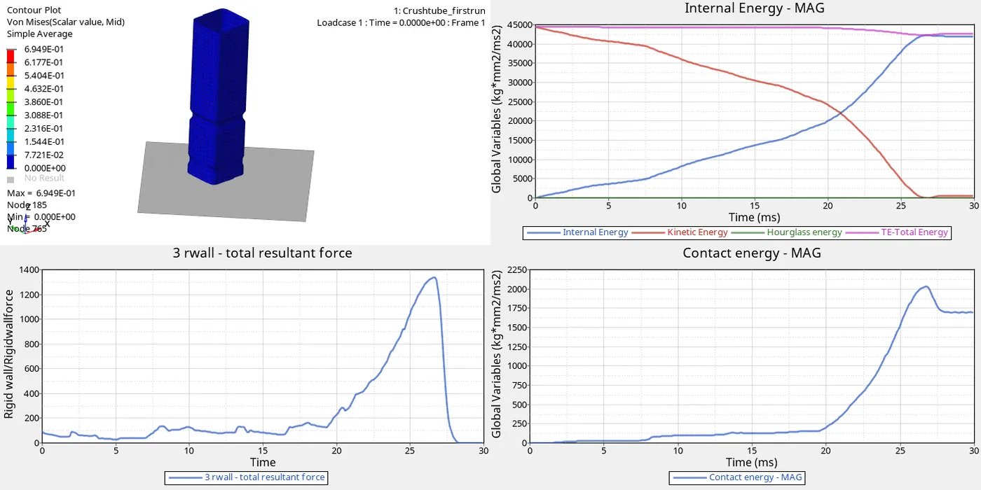
Von-mises stress shows the maximum peak value of 6.949E+01 is at node 185
Von-mises stress shows the minimum value of 0.00E+00 is at node 765.
Maximum displacement: 2.800E+02 is at node 765
Minimum displacement: 0.000E+00 is at node 765.
11.Import the T01 file from the 0001 files to view the analysis in Graphical format.
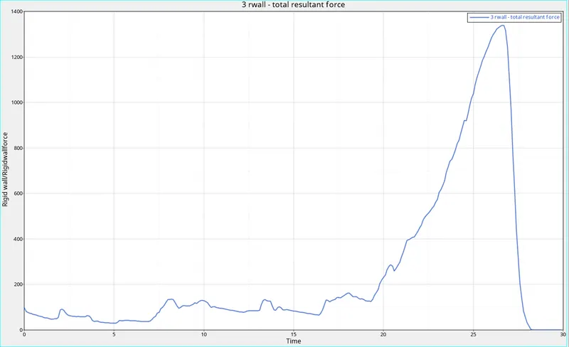
12. For the Rigid wall, Forces choose Rigid wall/ Rigidwall force > 3wall > Total Resultant Force > mag > Apply.
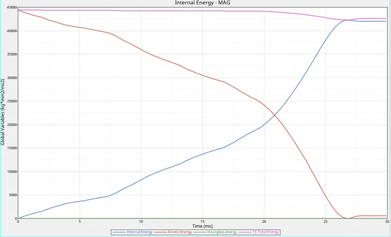
13. For the Energy graph choose the energies to be plotted, Global variables > Kinetic Energy, Internal energy, Contact energy, Hourglass energy, Total Energy > MAg, and choose to Apply.
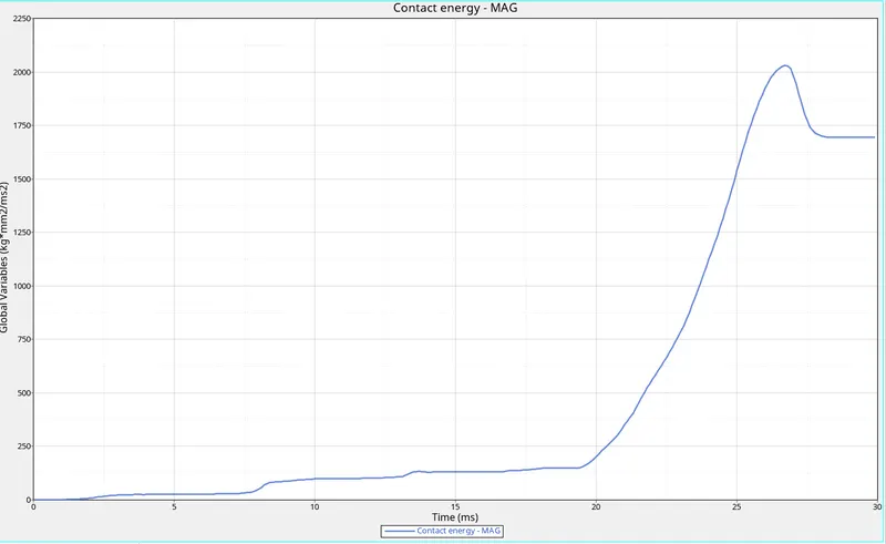
14.To Check the Internal energy for each part choose > P shell 1, P shell 2, P shell 2mm, P shell2_2mm > Mag > Apply.
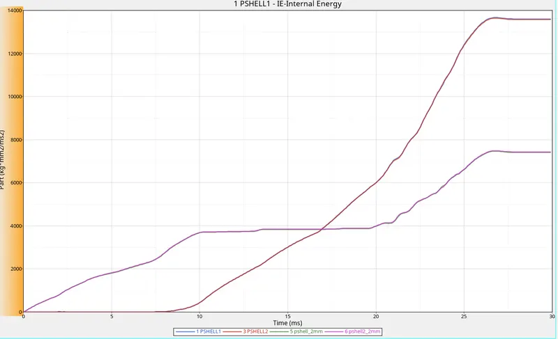
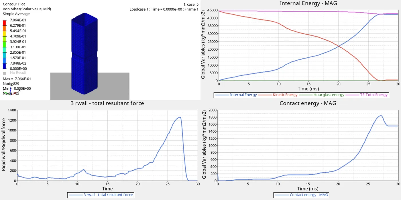
15. As the Model contains Four Parts with variable Thickness Internal energy Graph is Plotted according to that.
Observation From The graph:
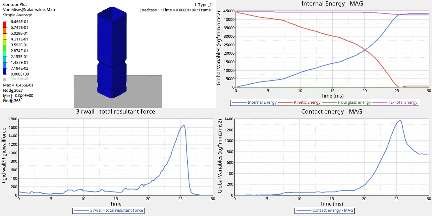
- The Crash Tube consists of Two Grooves, Grooving is used to shape the path of deformation to occur.
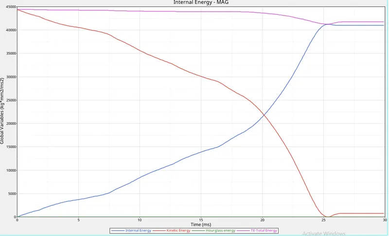
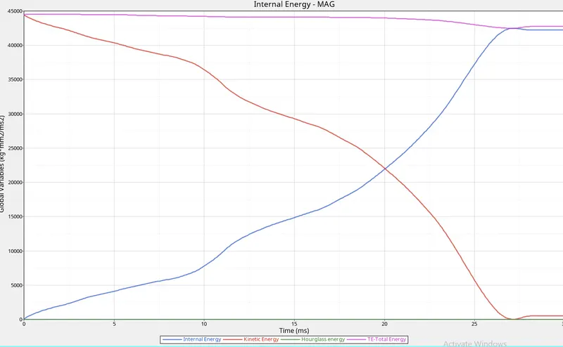
- Kinetic Energy is maximum at 45000 and, it decreases with time and reaches zero points,
- Internal energy starts from zero, due to the deformation that occurs, the internal energy raises steadily till the rebound condition and becomes steady.
- There is no hourglass energy observed in the crash.
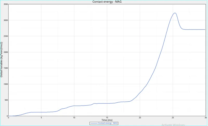
- Contact Energy is the sum of Both forces acting in Slave and master nodes when comes in contact.
CASE-2: Change the Inacti = 6 and run
1.Import the given crush tube model into Hypermesh
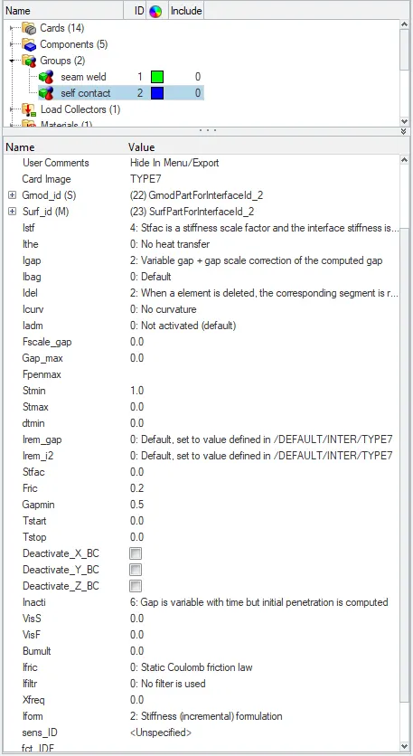
2.Change the Inacti = 6, which can be used to reduce and scale the gap is one of the methods for removing initial penetration. And the parameters were changed According to the type such as value for Istiff, Idel, Gapmin, are given
3.Click on the analysis panel in the Hypermesh.
4.Save the model in the local directory.
5.For Running The analysis: Analysis > Radioss is selected from the panel
6. The analysis runs and shows the result.
7. The energy error And mass errors are checked.
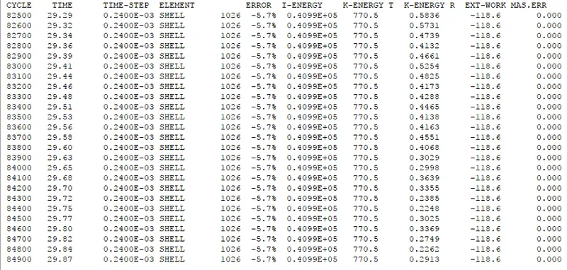
8.From the result the energy error is -5.7% and the mass error is found out to be 0.000, which lies in the acceptable Conditions.
9.Click results for viewing the Analysis in an Animated and Graphical Format.
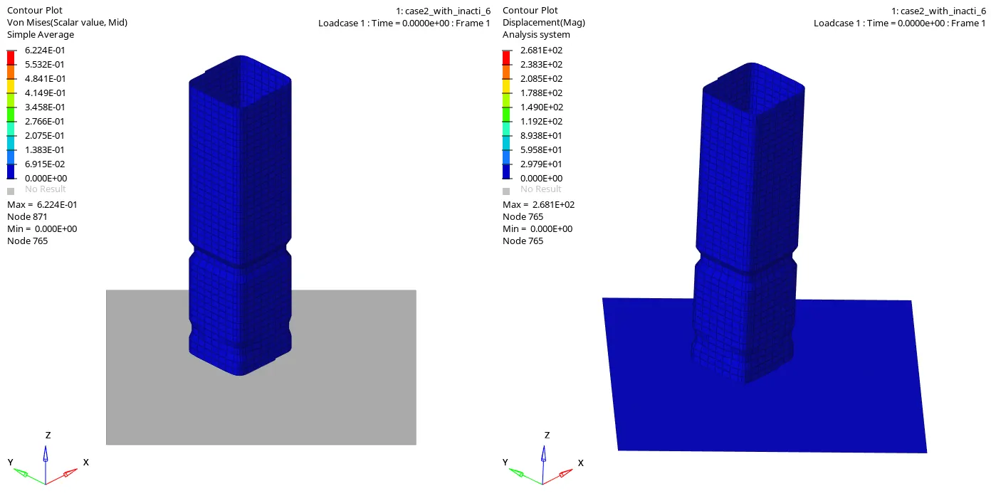
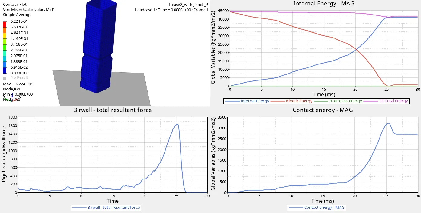
Von-mises stress shows the maximum peak value of 6.224E+01 is at node 871
Von-mises stress shows the minimum value of 0.00E+00 is at node 765.
Maximum displacement: 2.681E+02 is at node 765
Minimum displacement: 0.000E+00 is at node 765.
10. In the Above Case There is no Inacti=6 activated so there will be no energy that avoids Pushing the elements penetrating In the initial condition.
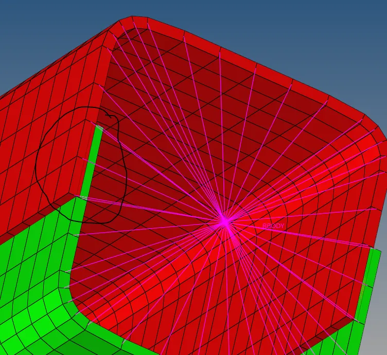
11. As in this case Inacti=6 is activated additional energy is Produced to oppose the elements penetrating This leads to comparatively High energy error with case 1.
12. Import the T01 file from the 0001 files to view the analysis in Graphical format.
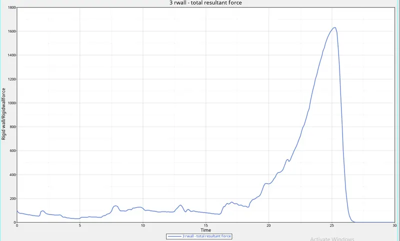
13. For the Rigid wall, Forces choose Rigid wall/ Rigidwall force > 3wall > Total Resultant Force > mag > Apply.
14.For the Energy graph choose the energies to be plotted, Global variables > Kinetic Energy, Internal energy, Contact energy, Hourglass energy, Total Energy > MAg, and choose to Apply.
15. To Check the Internal energy for each part choose > P shell 1, P shell 2, P shell 2mm, P shell2_2mm > Mag > Apply.
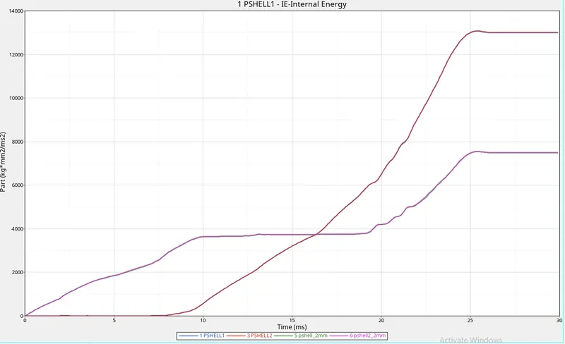
16. Similar to the first case, in this initial penetrations, are avoided by activating Inacti as 6, all other data is the same as observed in case 1.
CASE-3: CREATE TYPE 11 CONTACT AND RUN:
1.Import the given crush tube model into Hypermesh
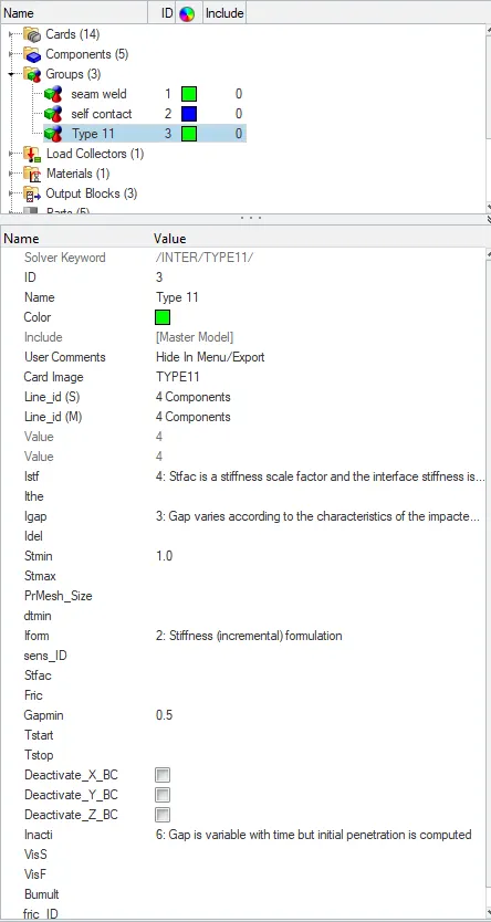
2.Change the Interface As Type=11 (Edge to Edge contact), And the parameters were changed According to the type such as value for Istiff, Idel, Gapmin, are given.
3.Click on the analysis panel in the Hypermesh.
4.Save the model in the local directory.
5.For Running The analysis: Analysis > Radioss is selected from the panel
6. The analysis runs and shows the result.
7. The energy error And mass errors are checked.

8.As the energy error is -1.7% which is less than 15% so it is acceptable, also the mass error is found out to be 0.000
9.Click results for viewing the Analysis in an Animated and Graphical Format.
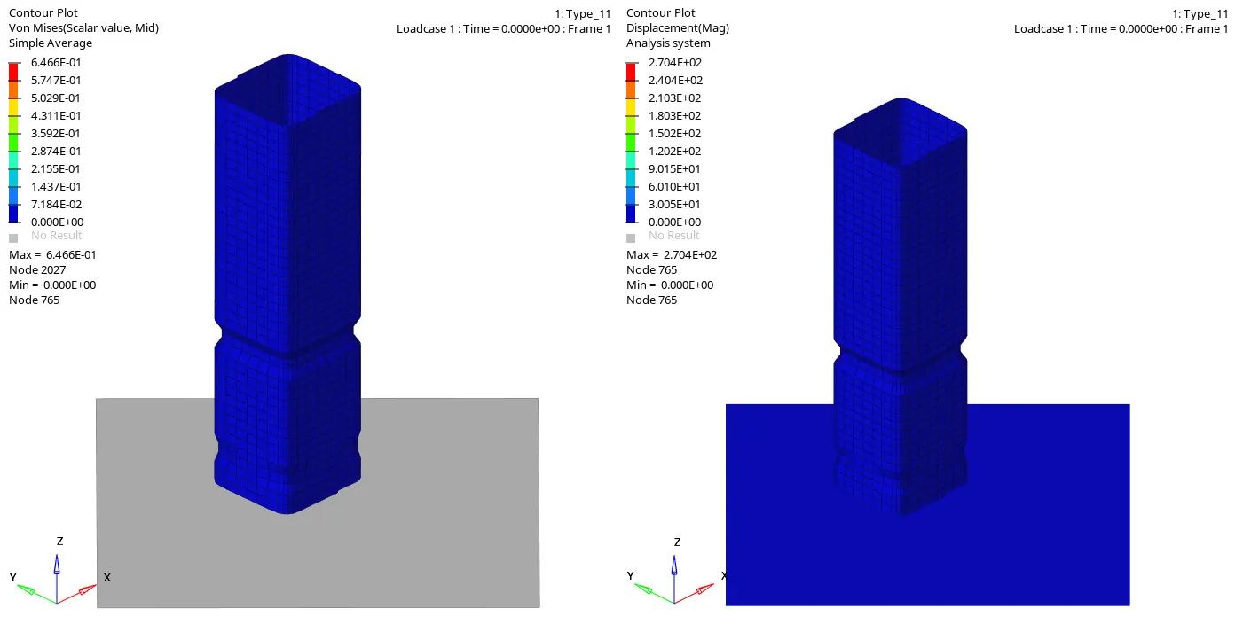
Von-mises stress shows the maximum peak value of 6.466E+01 is at node 2027
Von-mises stress shows the minimum value of 0.00E+00 is at node 765.
Maximum displacement: 2.704E+02 is at node 765
Minimum displacement: 0.000E+00 is at node 765.
10. Import the T01 file from the 0001 files to view the analysis in Graphical format.
11. For the Rigid wall, Forces choose Rigid wall/ Rigidwall force > 3wall > Total Resultant Force > mag > Apply.
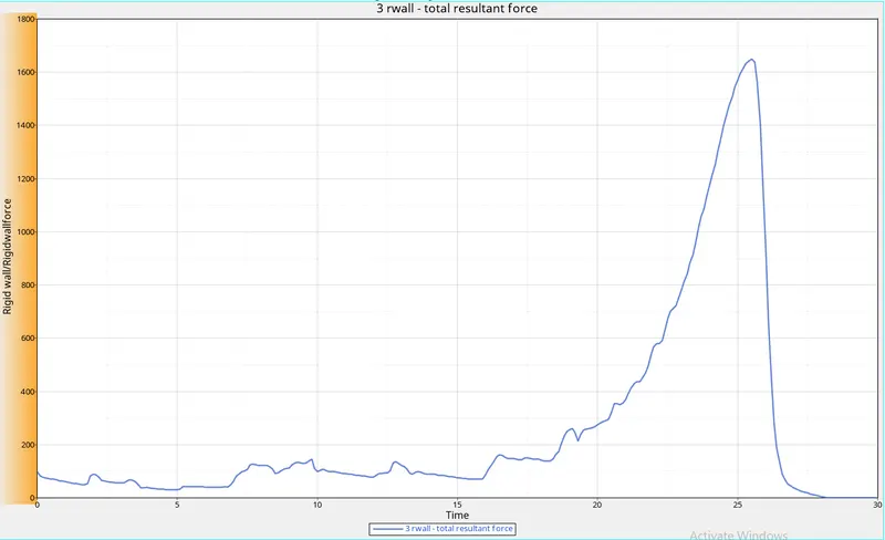
12.For the Energy graph choose the energies to be plotted, Global variables > Kinetic Energy, Internal energy, Contact energy, Hourglass energy, Total Energy > MAg, and choose to Apply.
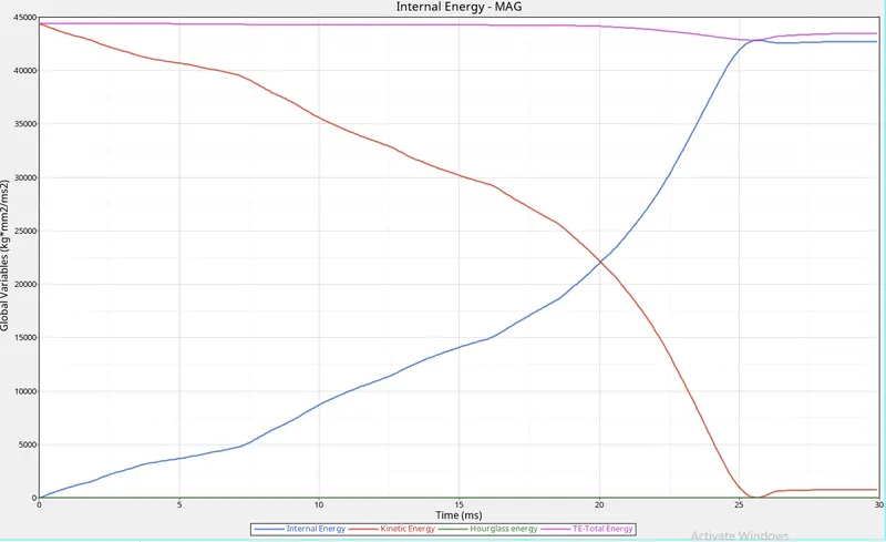
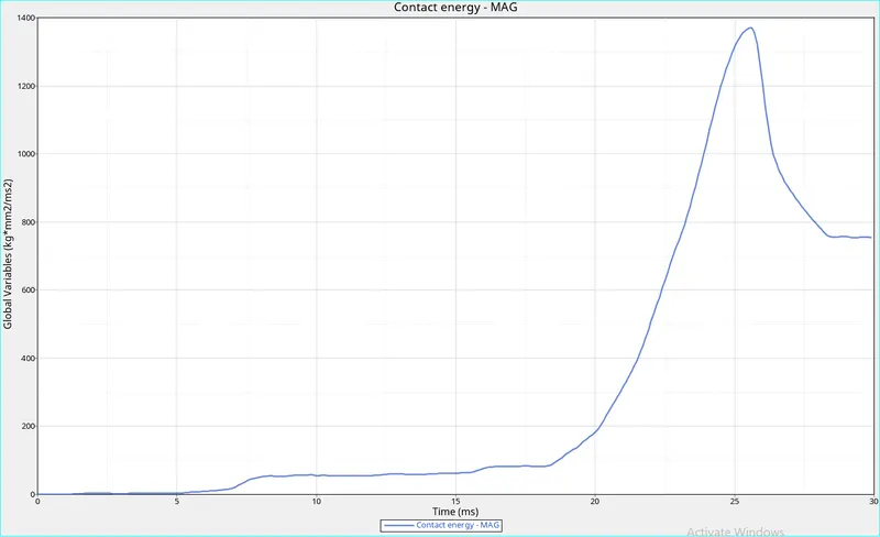
13. To Check the Internal energy for each part choose > P shell 1, P shell 2, P shell 2mm, P shell2_2mm > Mag > Apply.
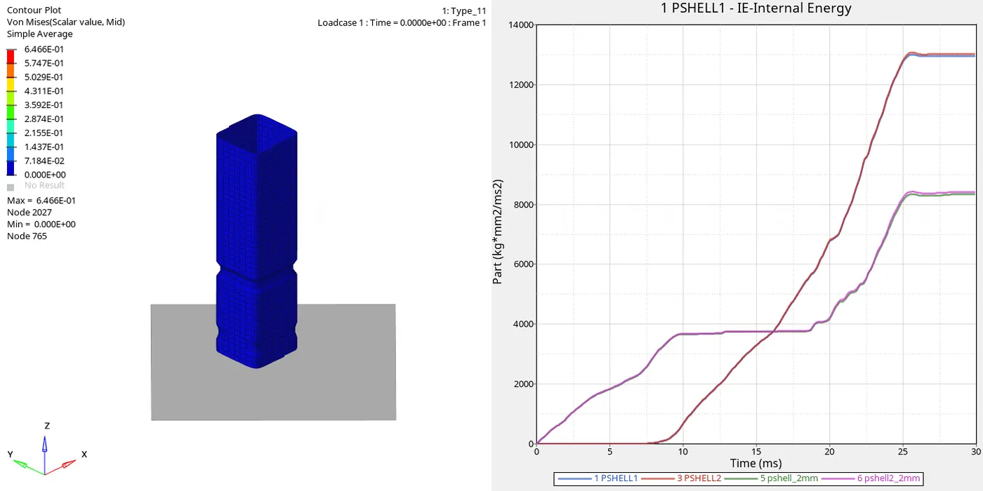
14. As the P SHELL-1 and P SHELL-2 are in contact with the rigid wall surface It deforms first while the load is applied so it starts from 0
15.The other 2 shells start deforming later compared with P shells 1 and 2. they start deforming at 7s.
16. Due to the variable Thickness in P Shell 1 and 2 it deforms less compared with the Other Components.
CASE-4:Remove both notches and remove boundary conditions on rigid body node then run
1. Import the given crush tube model into hHypermesh
2. Tthe notches are removed by aligning the nodes using the node edit option available under the geometry panel or (F7)
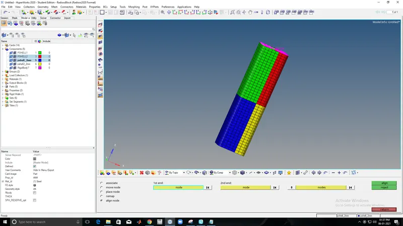
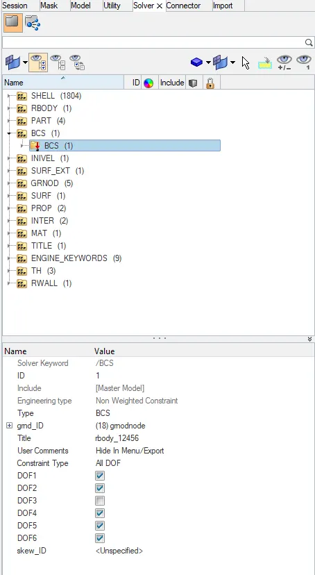
3. The boundary conditions which are available in the Solver area as BCS are deleted.
4. Click on the analysis panel in the Hypermesh.
5. Save the model in the local directory.
6. For Running The analysis: Analysis > Radioss is selected from the panel
7. The analysis runs and shows the result.
8. The energy error And mass errors are checked.
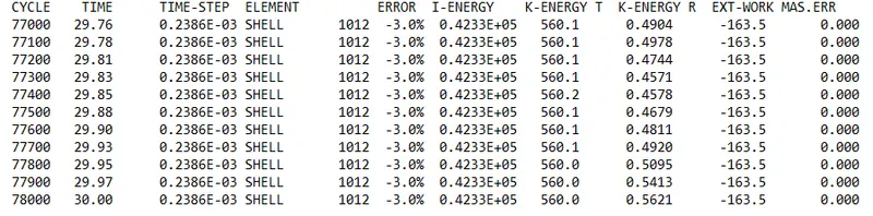
9.As the energy error is -3.0% which is less than 15% so it is acceptable, also the mass error is found out to be 0.000
10.Click results for viewing the Analysis in an Animated and Graphical Format.
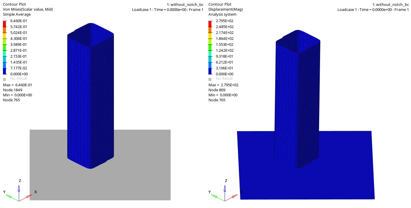
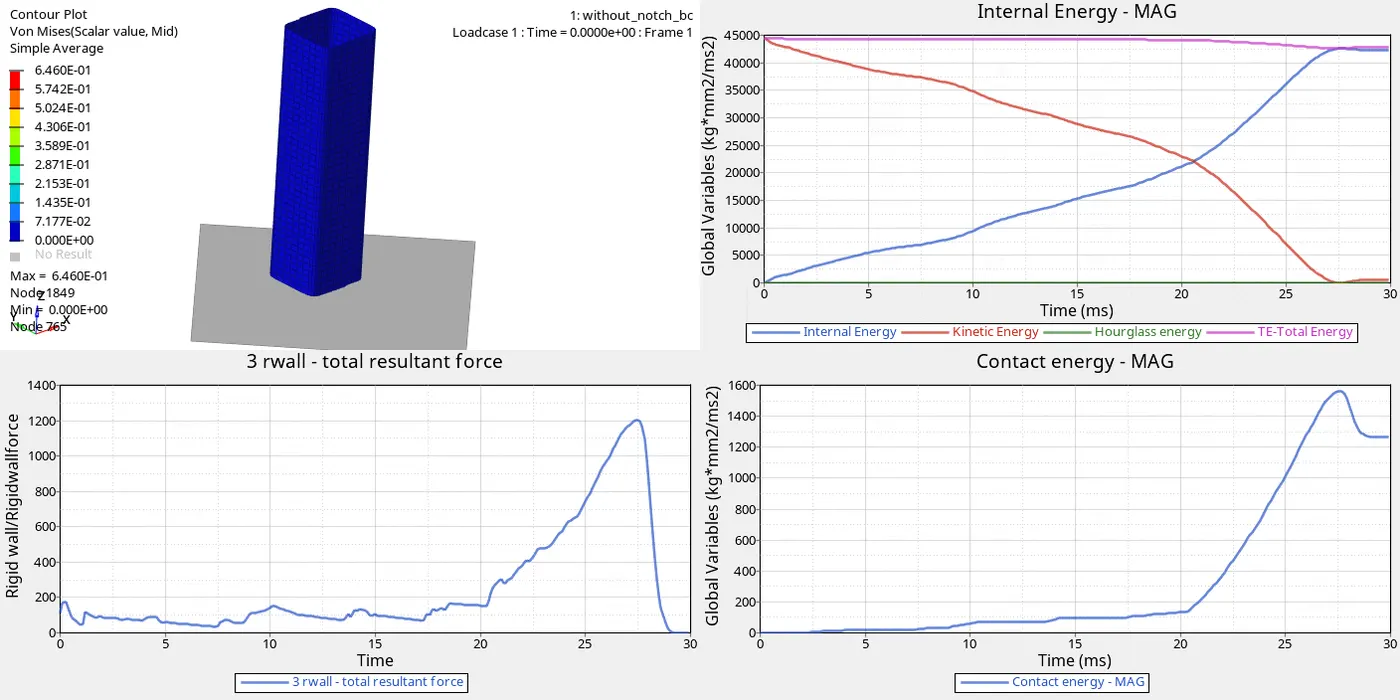
Von-mises stress shows the maximum peak value of 6.460E-01 is at node 1849
Von-mises stress shows the minimum value of 0.00E+00 is at node 765.
Maximum displacement: 2.795E+02 is at node 809
Minimum displacement: 0.000E+00 is at node 765.
11.Import the T01 file from the 0001 files to view the analysis in Graphical format.
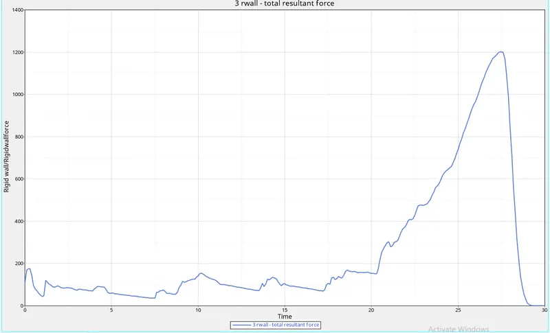
12. For the Rigid wall, Forces choose Rigid wall/ Rigidwall force > 3wall > Total Resultant Force > mag > Apply.
13.For the Energy graph choose the energies to be plotted, Global variables > Kinetic Energy, Internal energy, Contact energy, Hourglass energy, Total Energy > MAg, and choose to Apply.
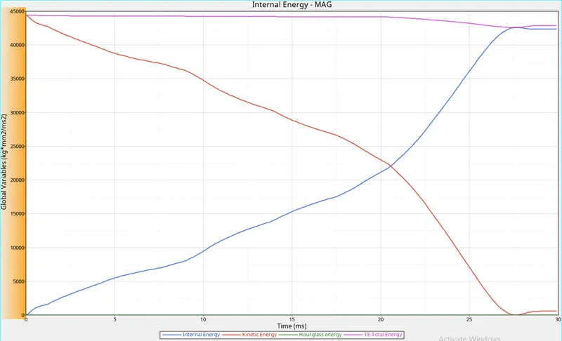
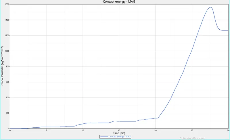
14. To Check the Internal energy for each part choose > P shell 1, P shell 2, P shell 2mm, P shell2_2mm > Mag > Apply.
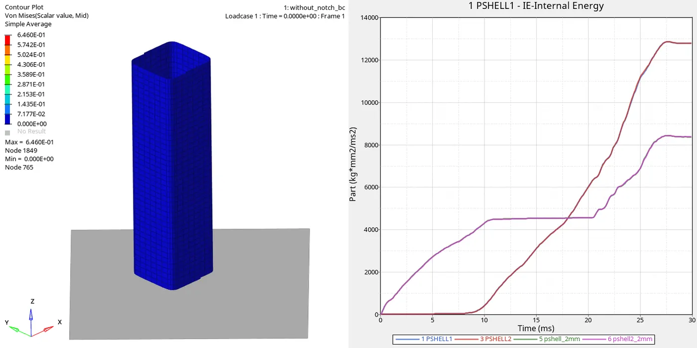
15. As the P SHELL-1 and P SHELL-2 are in contact with the rigid wall surface It deforms first while the load is applied so it starts from 0
16. As the Notch is removed here the Other two components experience the force acting in a way much quicker compared to the case before.
without notch With Notch
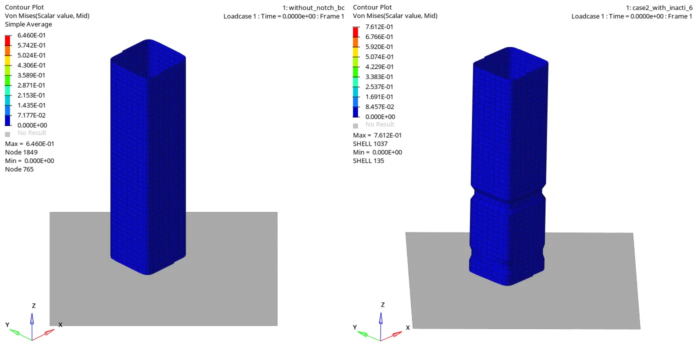
17.As the Deformation in the model with a notch is quite linear as the deformation occurs in the panel which is in contact with the rigid wall first and moves to the component above the notch
18.whereas in the model without a notch the force is distributed Uniformly throughout the components.
CASE-5:Create a new notch in the middle, select the whole section and run
1.Import the given crush tube model into Hypermesh
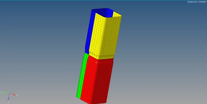
2. The notches were removed in the model and created in the middle of the model
3.The nodes in the middle are selected and translated in a negative direction along the axis, using the translate option in the Tools pannel.
5. Click on the analysis panel in the Hypermesh.
6. Save the model in the local directory.
7. For Running The analysis: Analysis > Radioss is selected from the panel
8. The analysis runs and shows the result.
9. The energy error And mass errors are checked.
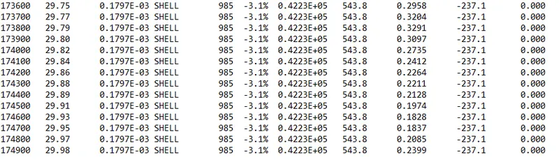
10.As the energy error is -3.1% which is less than 15% so it is acceptable, also the mass error is found out to be 0.000
11.Click results for viewing the Analysis in Animated and Graphical Format.
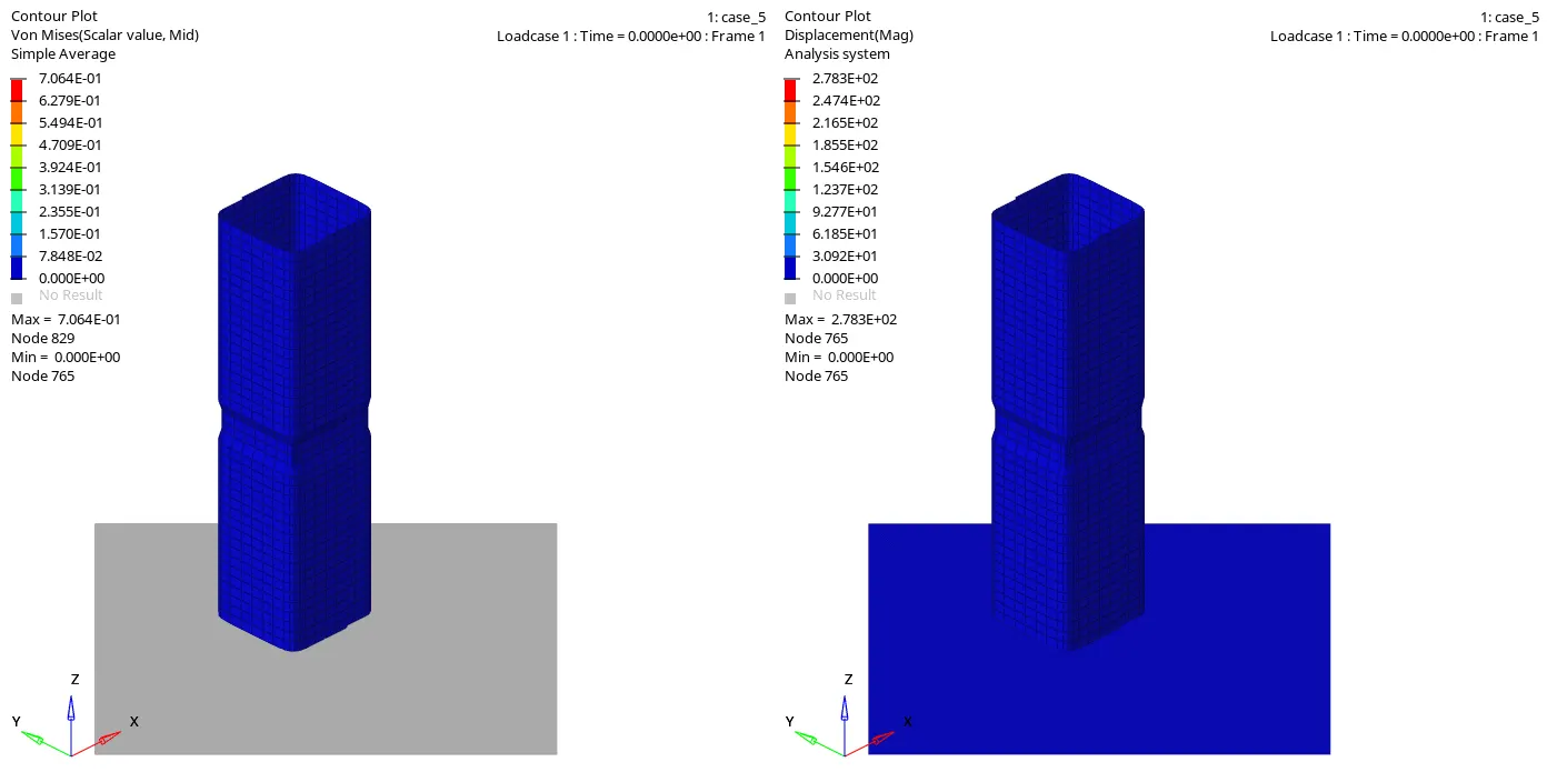
Von-mises stress shows the maximum peak value of 7.064E-01 is at node 829
Von-mises stress shows the minimum value of 0.00E+00 is at node 765.
Maximum displacement: 2.783E+02 is at node 765
Minimum displacement: 0.000E+00 is at node 765.
12. Import the T01 file from the 0001 files to view the analysis in Graphical format.
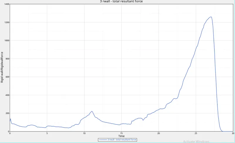
13. For the Rigid wall, Forces choose Rigid wall/ Rigidwall force > 3wall > Total Resultant Force > mag > Apply
14. For the Energy graph choose the energies to be plotted, Global variables > Kinetic Energy, Internal energy, Contact energy, Hourglass energy, Total Energy > MAg, and choose to Apply.
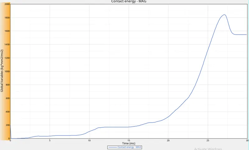
15.To Check the Internal energy for each part choose > P shell 1, P shell 2, P shell 2mm, P shell2_2mm > Mag > Apply.
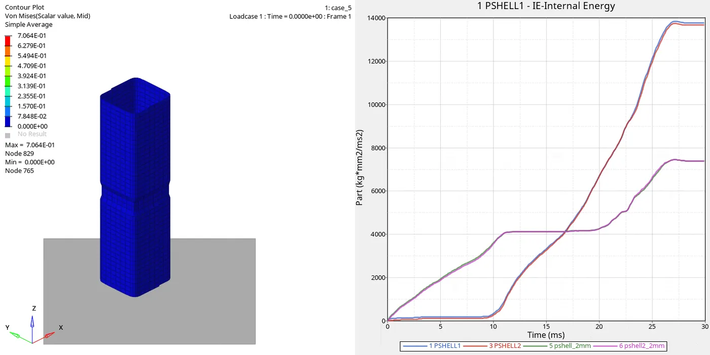
16. As in this model due to the force applied the buckling starts in the middle so all the 4 components experiences deformation equally starting from 0 secs.
17.Due to the variable thickness the Internal energies vary for the components.
The Notch at Middle Default Notch position.
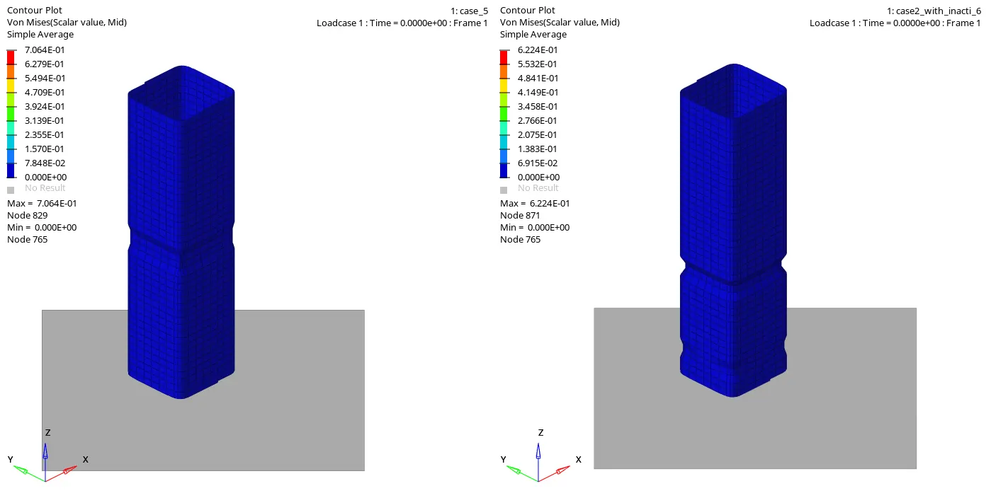
18. From the above Gif we can see that the Buckling occurs in a different Position in each Model because of the position of the notch placed
I.E of Notch in Middle I.E of Notch in Default Position.
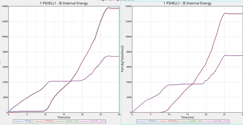
From the graph
* due to the Buckling acting in middle, All the components with the notch in between experience internal energy at the same Point.
* whereas in the Other case The Internal energy of P shell 1 and 2, starts from 0 and the other 2 starts slightly later.
CASE-6: Create a new notch with nodes only from opposing two faces and run:
1.Import the given crush tube model into Hypermesh
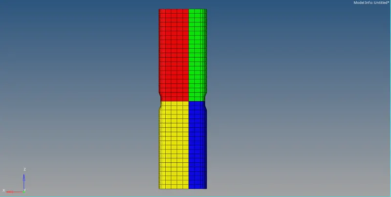
2.In this case, the notches which were removed like in case 4 are created again but only to the opposing two faces.
3.This can be done by using the translate option which is available in the Tools panel.
4. For Running The analysis: Analysis > Radioss is selected from the panel
5.Save the model in the local directory.
6. The analysis runs and shows the result.
7. The energy error And mass errors are checked.

8.As the energy error is -2.9% which is less than 15% so it is acceptable, also the mass error is found out to be 0.000
9.Click results for viewing the Analysis in Animated and Graphical Format.
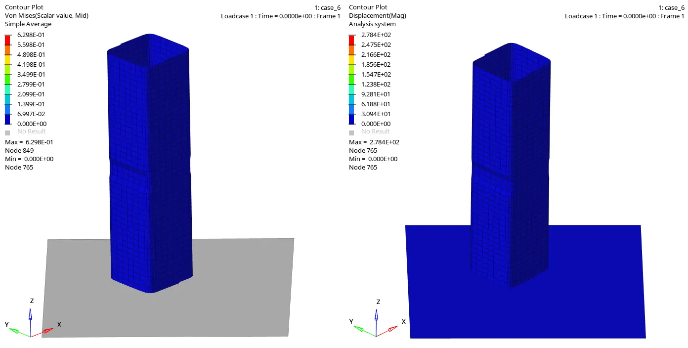
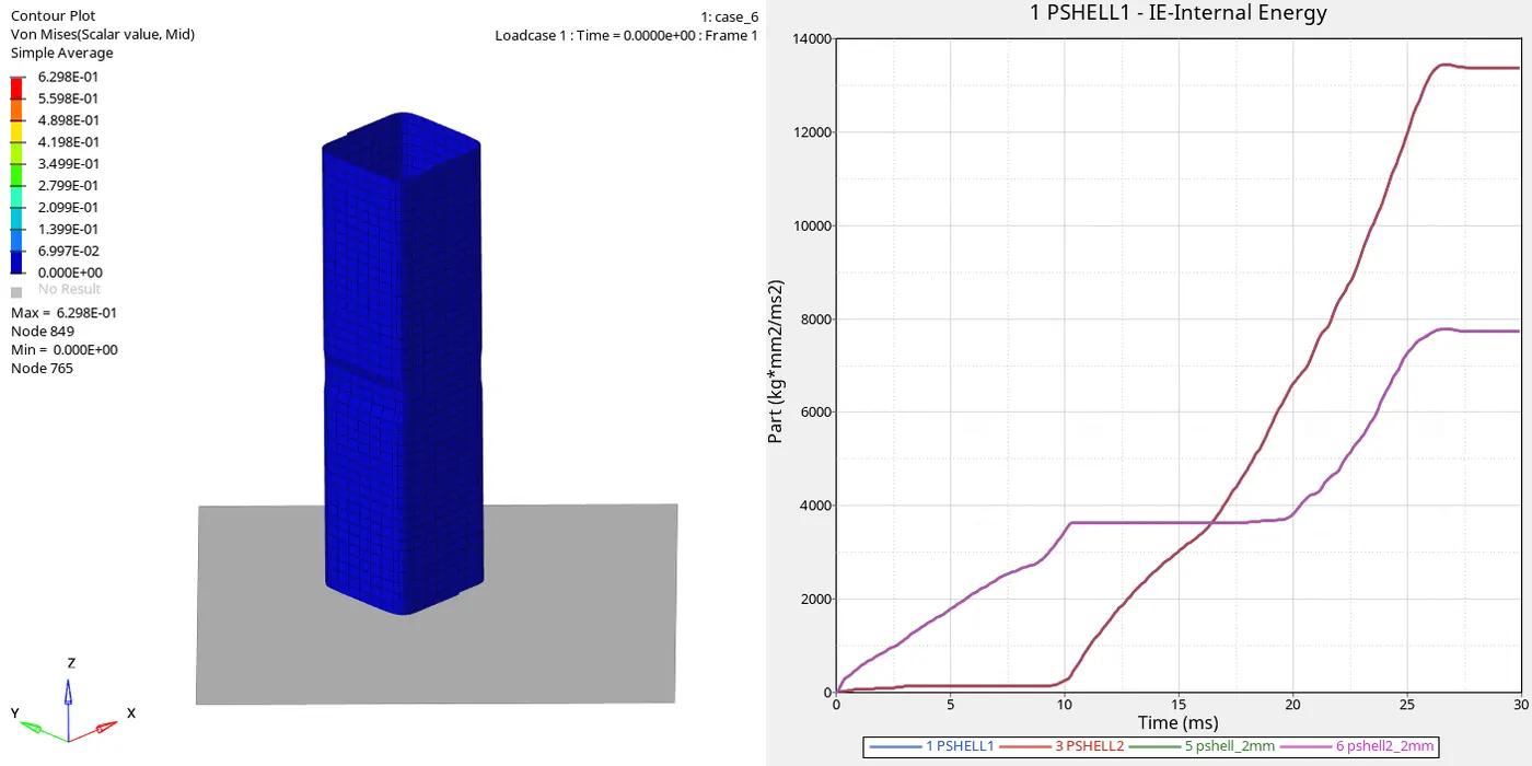
Von-mises stress shows the maximum peak value of 6.298E-01 is at node 849
Von-mises stress shows the minimum value of 0.00E+00 is at node 765.
Maximum displacement: 2.784E+02 is at node 765
Minimum displacement: 0.000E+00 is at node 765.
10.Import the T01 file from the 0001 files to view the analysis in Graphical format.
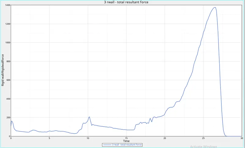
11. For the Rigid wall, Forces choose Rigid wall/ Rigidwall force > 3wall > Total Resultant Force > mag > Apply
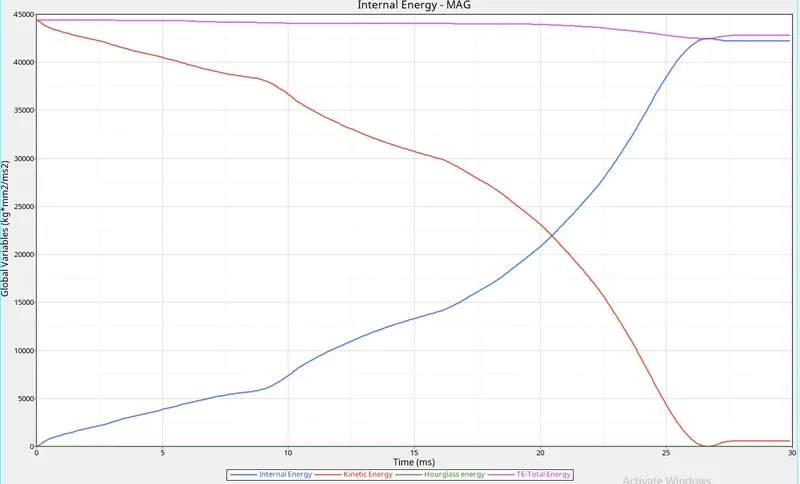
12.For the Energy graph choose the energies to be plotted, Global variables > Kinetic Energy, Internal energy, Contact energy, Hourglass energy, Total Energy > MAg, and choose to Apply.
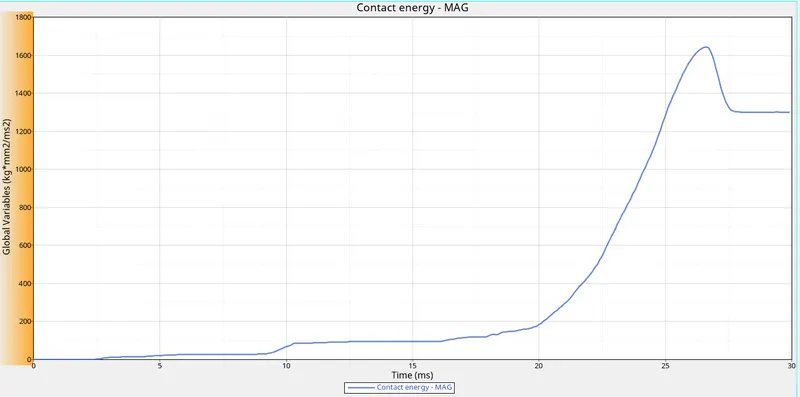
13.To Check the Internal energy for each part choose > P shell 1, P shell 2, P shell 2mm, P shell2_2mm > Mag > Apply.
From the Graph.
*The Grooving region attracts the flow direction of the force.
*Energies plots are similar to all the cases.
* The buckling occurs as same as in the above case.
Case-2 vs, case-5 vs, case-6.
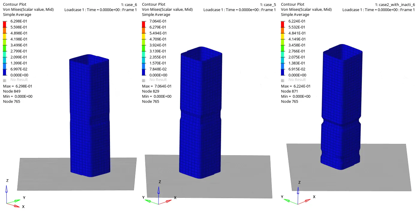
Comparison with Graph:
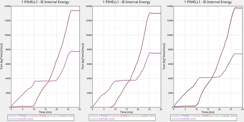
Here the notches present only on the opposing hence it resists forces from the rigid wall due to which the results obtained are not ideal.
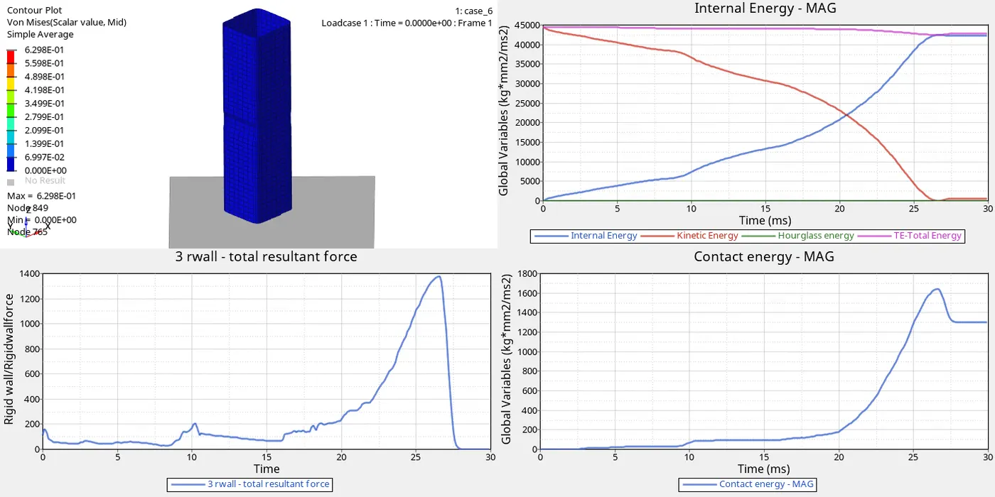
Comparison of all the cases:
| Type of contact | Number of cycles | Energy error | Mass error | Simulation time | Remarks |
| Case 1: Run the model as it is (TYPE7 contact without the recommended values) | 83496 | -3.8% | 0.000 | 137.13 s | The basic simulation was performed and energy error and mass error are quite ok with the boundary conditions |
| Case 2: Change the Inacti=6 (TYPE7 contact without the recommended values) | 85449 | -5.7% | 0.000 | 178.05 s | Inacti=6 value is given as 6 which will give resistive force with respect to time so that the penetration will be removed. As in this case, Inacti=6 is activated additional energy is Produced to oppose the elements penetrating This leads to comparatively High energy error with case 1. |
| Case 3: Change to TYPE11 contact | 105557 | -1.7% | 0.000 | 350.37 s | Here the number of cycles and simulation time is increased due to the type of contact being edge to edge self impact contact but the energy error is significantly reduced compared to other cases |
| Case 4: Remove both notches and remove the boundary conditions on rigid body | 78015 | -3.0% | 0.000 | 124.10 s | Since the notch has been removed it can be noted that the number of cycles is reduced but the energy error is increased compared to the previous case whereas the simulation time is manageable |
| Case 5: Create a new notch in the middle | 174988 | -3.1% | 0.000 | 270.06 s | Because of the creation of a new notch it the middle shows almost similar results to that of case 1&2 |
| Case 6: Create a new notch with nodes only from opposing two faces | 93666 | -2.9% | 0.000 | 155.71 s | Here the notches present only on the opposing hence it resists forces from the rigid wall due to which the results obtained is not ideal. |
CONCLUSION:
- From the Assignment, I've able to understand the process to create connections.
- gained knowledge about Interface and its types.
- Create Types of interfaces and what are their parameters defines.
- Understood How energies acting on it and get to know the values of it.