RADIOSS Material Laws study
Objective: To study material laws 1 (M1_ELAST), 2 (M2_PLAS_JOHNS_ZERIL), 27 (M27_PLAS_BRIT), and 36 (M36_PLAS_TAB) with a rupture plate example.
Procedure:
1. Import the given 0000.rad file into hypermesh.
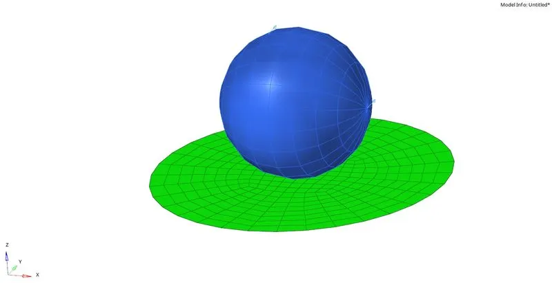
Fig 1: Geometry of plate and a rigid ball.
Case 1: LAW 2.
- The material card values and the failure card values are not altered.
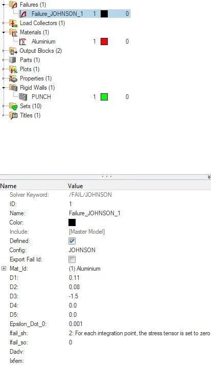
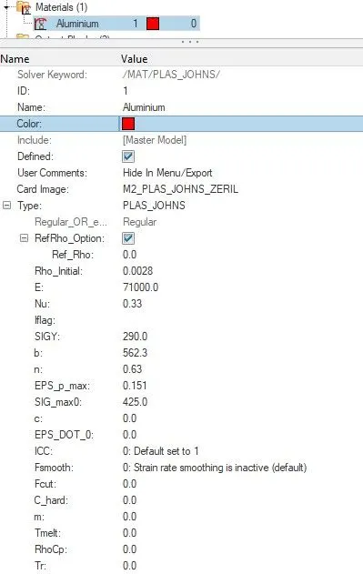
Fig 2: Failure and material card values.
- Now we can proceed to run our simulation. Navigate to the analysis tab and choose the radioss option.
- Input file option will be available to save the starter and engine file in the desired location.
- In the options bar, "-nt 6" is entered, which denotes parallel processing for the simulation.

Fig 3: Saving the file with an appropriate name.
- Once all the options are selected correctly, click on the radioss button to run the simulation.
- A separate window pops up and shows the calculation going on, and it might take up to few seconds to minutes based on the complexity of the solution.
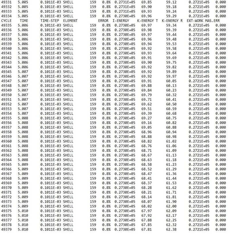
Fig 4: 0001.out files contains the solution information.
- We can check for the energy and mass error from the engine output file whether it lies within the permissible limit or not.
- The energy error starts from -0.3 to 0.8%, and the mass error is 0. Both are in the acceptable range, and we can proceed with the post-processing of our results.
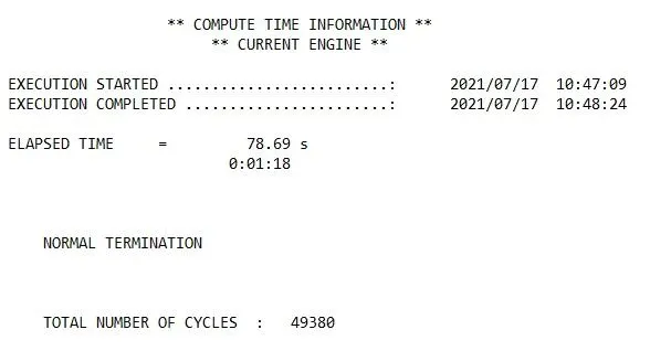
Fig 5: Compute time information.
- ELAPSED TIME = 78.69 s
- TOTAL NUMBER OF CYCLES: 49380
Results:
- For post-processing the results Hyperview and hypergraph are used.
- When hyperview is open, we need to load the model and results file of our simulation.

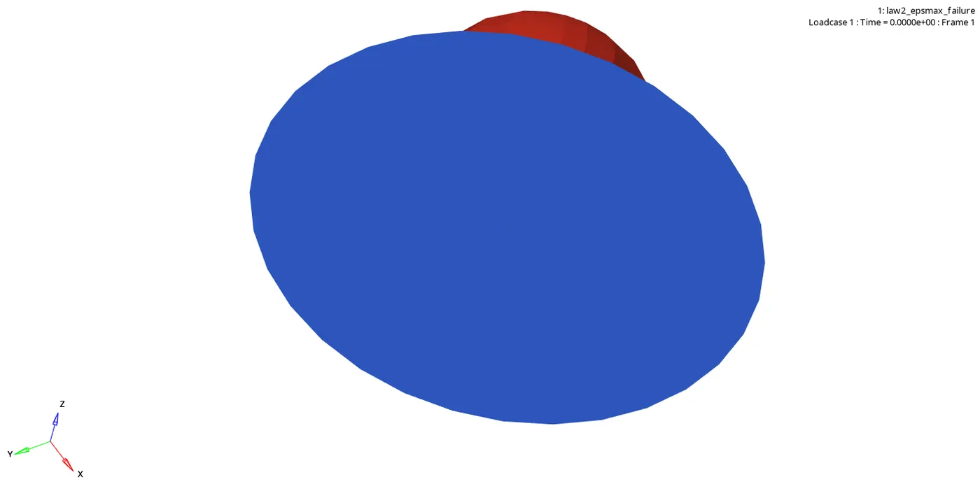
- The above animation represents the rupture plate when the rigid ball hits it.
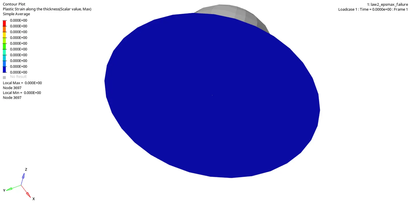
- The above animation represents the plastic stain on the plate, where the maximum value is 1.492E-01.
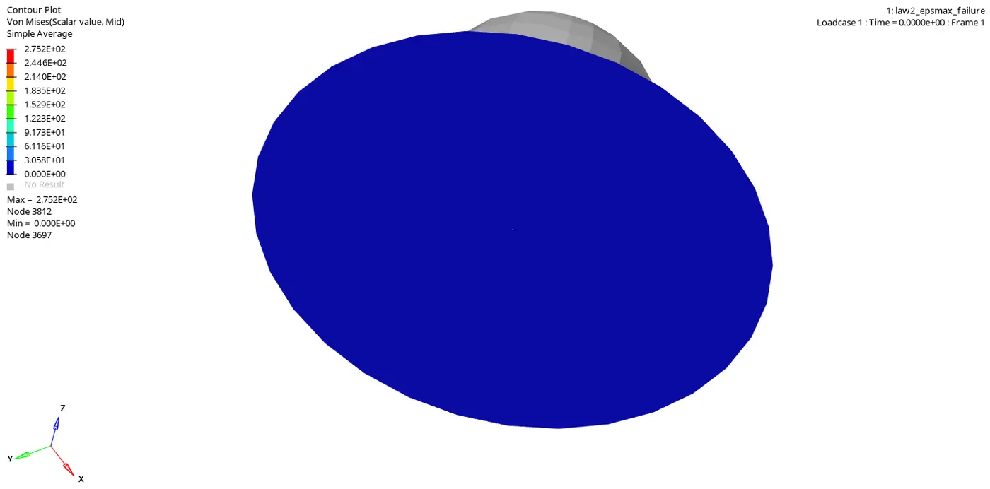
- The above animation represents the von mises stresses generated in the plate, and the maximum value is 2.752E+02.
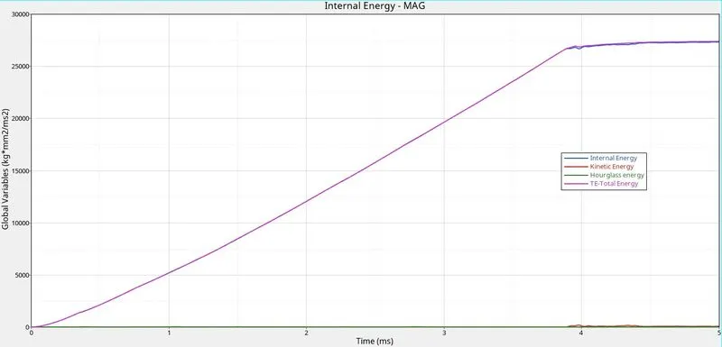
- The above plot shows the Total energy, Kinetic energy, Internal energy, and hourglass energy.
- The total energy is the summation of an internal, kinetic, hourglass, and contact energy.
- Internal energy is the sum of kinetic and potential energy in a system.
- The hourglass energy is controlled because of the element formulation.
Case 2: Law 2 with modified element failure parameters.
- The failure card values are modified as shown below.
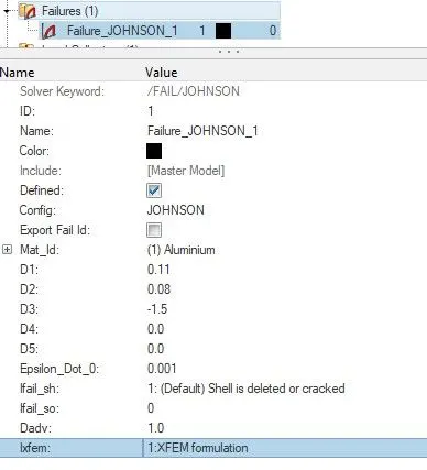
Fig 6: Modified values of the failure card.
- The material card values are not changed and kept as in case 1.
- Now we can proceed to run our simulation. Navigate to the analysis tab and choose the radioss option.
- Input file option will be available to save the starter and engine file in the desired location.
- In the options bar, "-nt 6" is entered, which denotes parallel processing for the simulation.
- Once all the options are selected correctly, click on the radioss button to run the simulation.
- A separate window pops up and shows the calculation going on, and it might take up to few seconds to minutes based on the complexity of the solution.
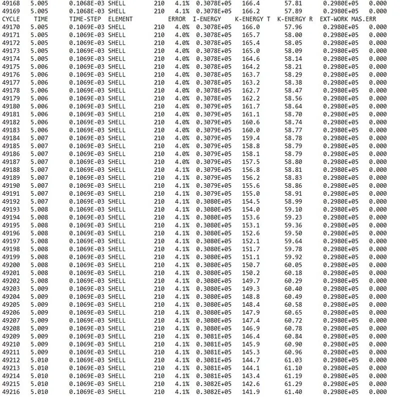
Fig 7: 0001.out files contains the solution information.
- We can check for the energy and mass error from the engine output file whether it lies within the permissible limit or not.
- The energy error starts from -0.3 to 4.1%, and the mass error is 0. Both are in the acceptable range, and we can proceed with the post-processing of our results.
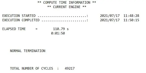
Fig 8: Compute time information.
- ELAPSED TIME = 110.79 s.
- TOTAL NUMBER OF CYCLES: 49217.
Results:
- For post-processing the results Hyperview and hypergraph are used.
- When hyperview is open, we need to load the model and results file of our simulation.
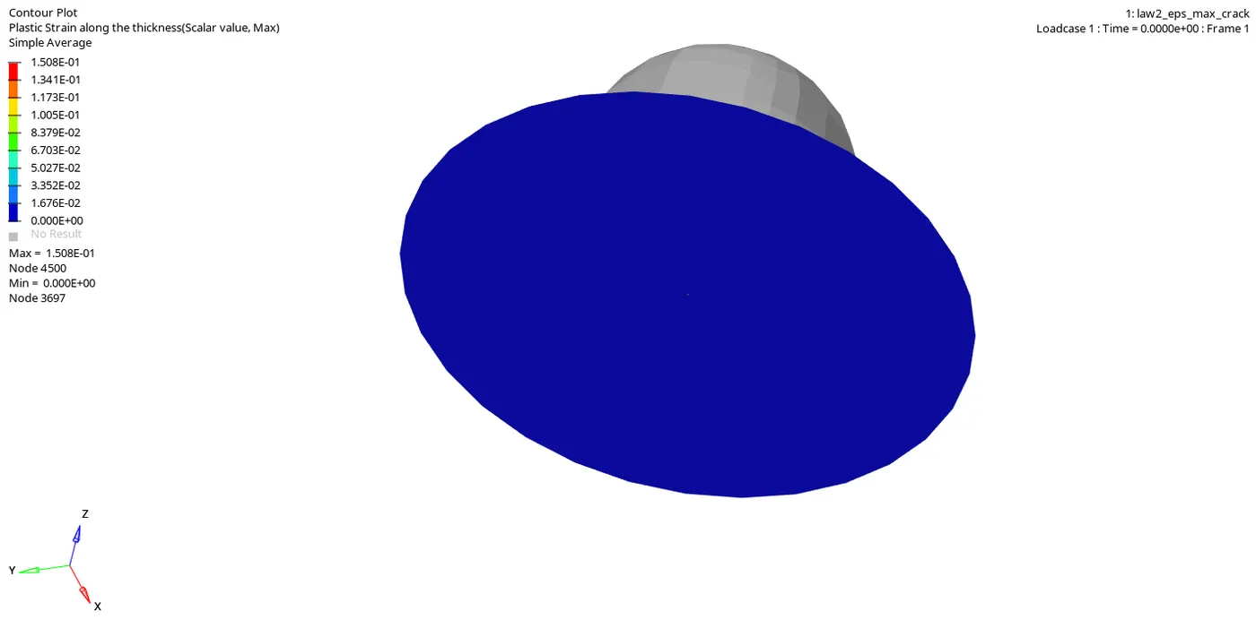
- The above animation represents the plastic stain on the plate, where the maximum value is 1.508E-01.
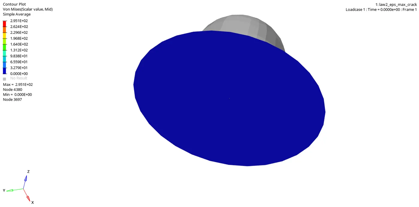
- The above animation represents the von mises stresses generated in the plate, and the maximum value is 2.951E+02.
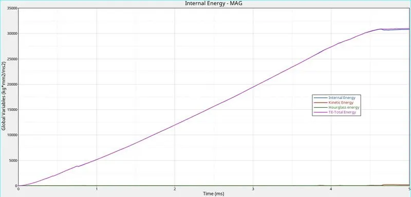
- The above plot shows the Total energy, Kinetic energy, Internal energy, and hourglass energy.
- The total energy is the summation of an internal, kinetic, hourglass, and contact energy.
- Internal energy is the sum of kinetic and potential energy in a system.
- The hourglass energy is controlled because of the element formulation.
Case 3: without failure card in Law 2.
- The failure card is deleted in this case.
- The other properties regarding the material are unaltered.
- Now we can proceed to run our simulation.
- Navigate to the analysis tab and choose the radioss option.
- Input file option will be available to save the starter and engine file in the desired location.
- In the options bar, "-nt 6" is entered, which denotes parallel processing for the simulation.
- Once all the options are selected correctly, click on the radioss button to run the simulation.
- A separate window pops up and shows the calculation going on, and it might take up to few seconds to minutes based on the complexity of the solution.
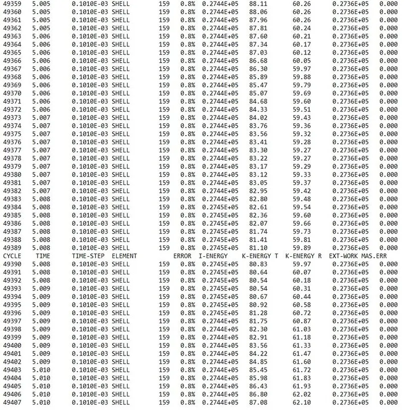
Fig 9: 0001.out files contains the solution information.
- We can check for the energy and mass error from the engine output file whether it lies within the permissible limit or not.
- The energy error starts from -0.3 to 0.8%, and the mass error is 0. Both are in the acceptable range, and we can proceed with the post-processing of our results.
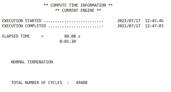
Fig 10: Compute time information.
- ELAPSED TIME = 80.08 s.
- TOTAL NUMBER OF CYCLES: 49408.
Results:
- For post-processing the results Hyperview and hypergraph are used.
- When hyperview is open, we need to load the model and results file of our simulation.
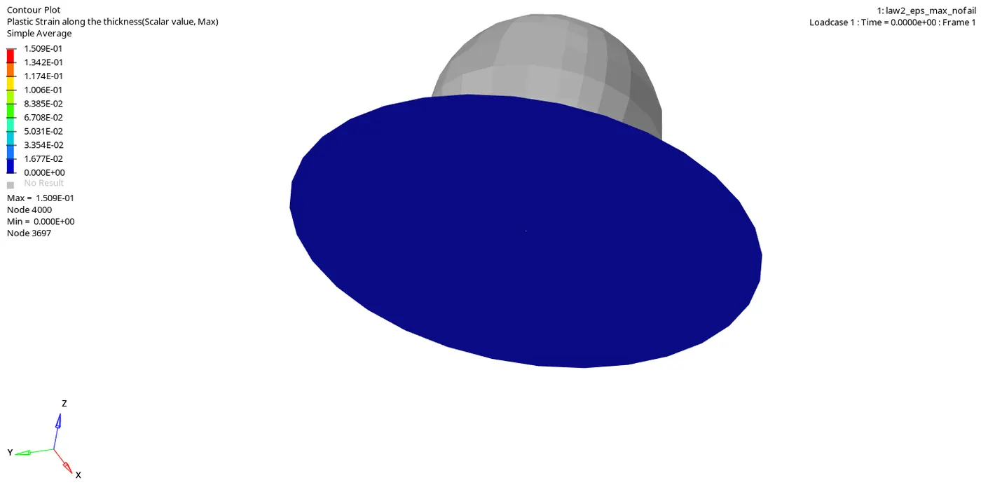
- The above animation represents the plastic stain on the plate, where the maximum value is 1.509E-01.
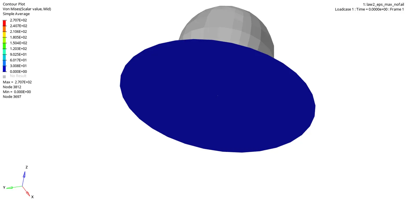
- The above animation represents the von mises stresses generated in the plate, and the maximum value is 2.707E+02.
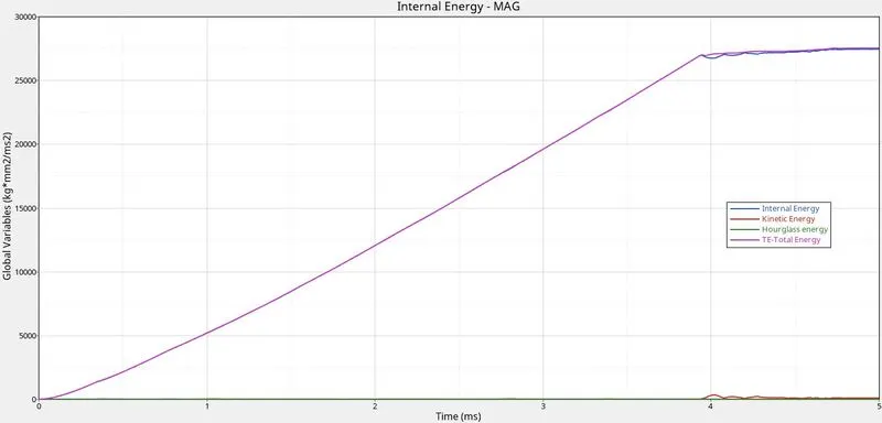
- The above plot shows the Total energy, Kinetic energy, Internal energy, and hourglass energy.
- The total energy is the summation of an internal, kinetic, hourglass, and contact energy.
- Internal energy is the sum of kinetic and potential energy in a system.
- The hourglass energy is controlled because of the element formulation.
Case 4: without EPS_p_mas value.
- In this case, the EPS_p_max value is set to zero in the material card.
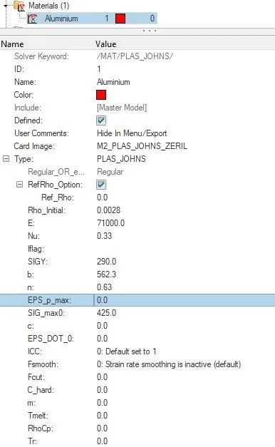
Fig 11: Material card with EPS_p_max value set to zero.
- Now we can proceed to run our simulation.
- Navigate to the analysis tab and choose the radioss option.
- Input file option will be available to save the starter and engine file in the desired location.
- In the options bar, "-nt 6" is entered, which denotes parallel processing for the simulation.
- Once all the options are selected correctly, click on the radioss button to run the simulation.
- A separate window pops up and shows the calculation going on, and it might take up to few seconds to minutes based on the complexity of the solution.
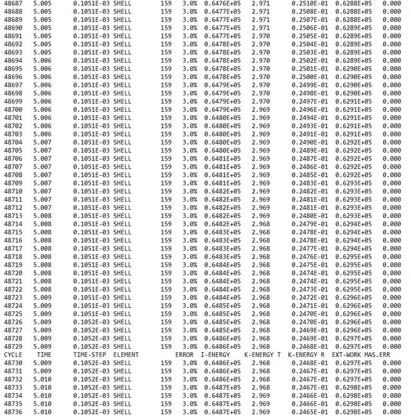
Fig 12: 0001.out files contains the solution information.
- We can check for the energy and mass error from the engine output file whether it lies within the permissible limit or not.
- The energy error starts from -0.3 to 3%, and the mass error is 0. Both are in the acceptable range, and we can proceed with the post-processing of our results.
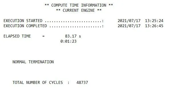
Fig 13: Compute time information.
- ELAPSED TIME = 83.17 s.
- TOTAL NUMBER OF CYCLES: 48737.
Results:
- For post-processing the results Hyperview and hypergraph are used.
- When hyperview is open, we need to load the model and results file of our simulation.
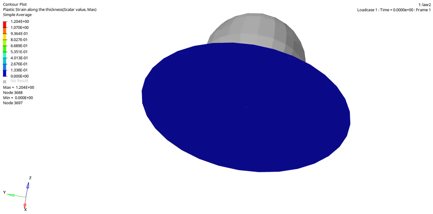
- The above animation represents the plastic stain on the plate, where the maximum value is 1.201E+00.
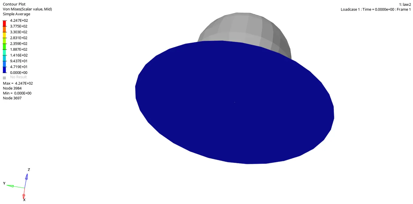
- The above animation represents the von mises stresses generated in the plate, and the maximum value is 4.247E+02.
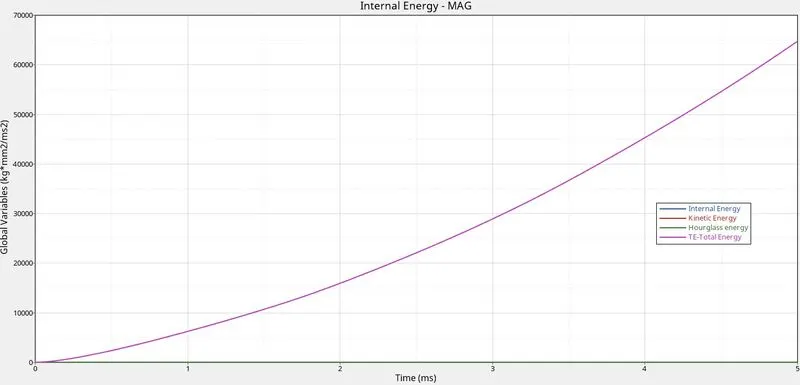
- The above plot shows the Total energy, Kinetic energy, Internal energy, and hourglass energy.
- The total energy is the summation of an internal, kinetic, hourglass, and contact energy.
- Internal energy is the sum of kinetic and potential energy in a system.
- The hourglass energy is controlled because of the element formulation.
Case 5: Law 1.
- The material card image is changed to M1_Elast, and the values of rho, E, and nu are entered to define the material properties completely.
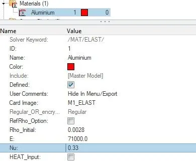
Fig 14: elastic material properties are assigned.
- Now we can proceed to run our simulation.
- Navigate to the analysis tab and choose the radioss option.
- Input file option will be available to save the starter and engine file in the desired location.
- In the options bar, "-nt 6" is entered, which denotes parallel processing for the simulation.
- Once all the options are selected correctly, click on the radioss button to run the simulation.
- A separate window pops up and shows the calculation going on, and it might take up to few seconds to minutes based on the complexity of the solution.
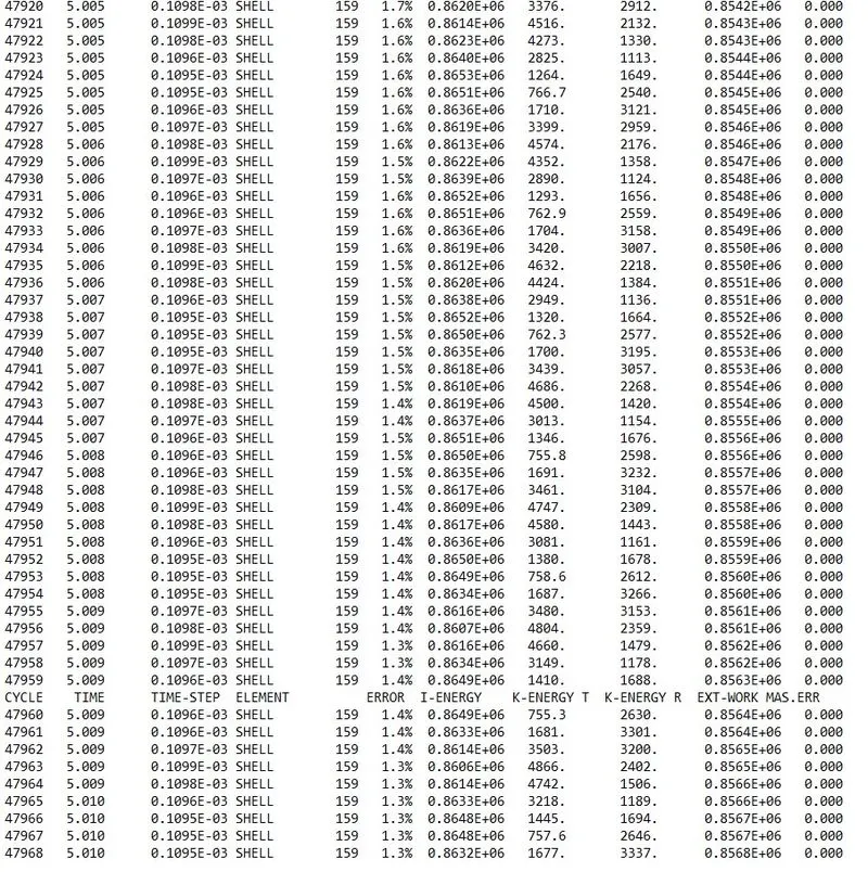
Fig 15: 0001.out files contains the solution information.
- We can check for the energy and mass error from the engine output file whether it lies within the permissible limit or not.
- The energy error starts from -0.3 to 1.3%, and the mass error is 0. Both are in the acceptable range, and we can proceed with the post-processing of our results.
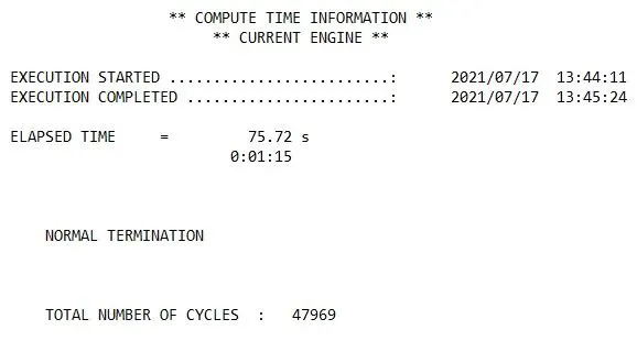
Fig 16: Compute time information.
- ELAPSED TIME = 75.72 s.
- TOTAL NUMBER OF CYCLES: 47969.
Results:
- For post-processing the results Hyperview and hypergraph are used.
- When hyperview is open, we need to load the model and results file of our simulation.
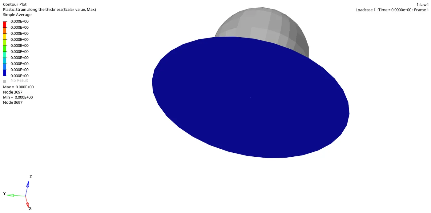
- The above animation represents the plastic stain on the plate, where the maximum value is 0.000E+00.
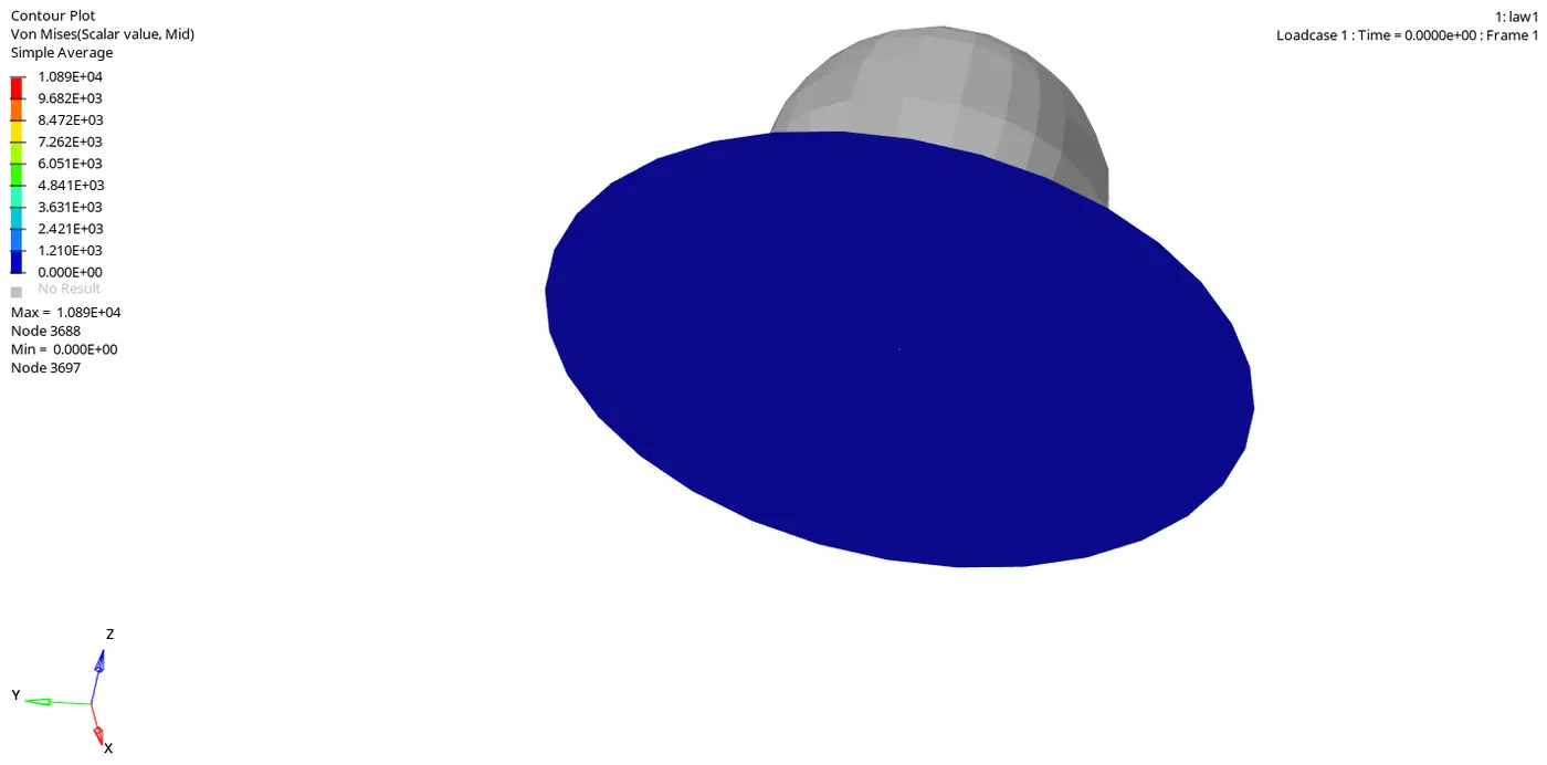
- The above animation represents the von mises stresses generated in the plate, and the maximum value is 1.089E+04.
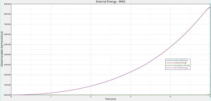
- The above plot shows the Total energy, Kinetic energy, Internal energy, and hourglass energy.
- The total energy is the summation of an internal, kinetic, hourglass, and contact energy.
- Internal energy is the sum of kinetic and potential energy in a system.
- The hourglass energy is controlled because of the element formulation.
Case 6: Law 27.
The card image for the material is changed to M27_PLAS_BRIT, and the required values to define the material are filled in.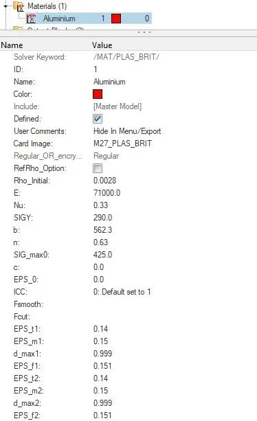
Fig 17: brittle material properties are assigned.
- EPS_t1 represents the tensile failure in which stress begins to reduce in the principal strain direction1.
- EPS_m1 represents the maximum tensile failure strain in the principal strain direction1 at which the stress in the element is set to a value dependent on dmax1.
- EPD_f1 represents the maximum tensile strain for the element deletion in the principal strain direction1.
- dmax1 represents the maximum damage factor in the principal direction1, which is a default value of 0.999.
- EPS_t2, EPS_m2, and EPS_f2 represents the direction2.
- Now we can proceed to run our simulation.
- Navigate to the analysis tab and choose the radioss option.
- Input file option will be available to save the starter and engine file in the desired location.
- In the options bar, "-nt 6" is entered, which denotes parallel processing for the simulation.
- Once all the options are selected correctly, click on the radioss button to run the simulation.
- A separate window pops up and shows the calculation going on, and it might take up to few seconds to minutes based on the complexity of the solution.
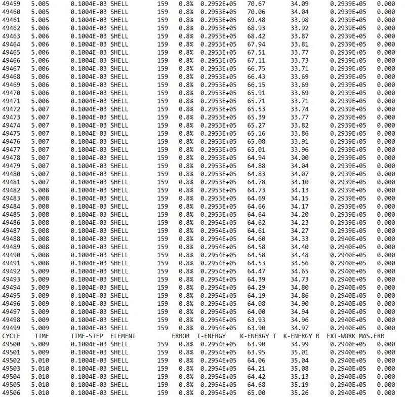
Fig 18: 0001.out files contains the solution information.
- We can check for the energy and mass error from the engine output file whether it lies within the permissible limit or not.
- The energy error starts from -0.3 to 0.8%, and the mass error is 0. Both are in the acceptable range, and we can proceed with the post-processing of our results.
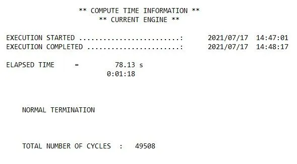
Fig 19: Compute time information.
- ELAPSED TIME = 78.13 s.
- TOTAL NUMBER OF CYCLES: 49508.
Results:
- For post-processing the results Hyperview and hypergraph are used.
- When hyperview is open, we need to load the model and results file of our simulation.
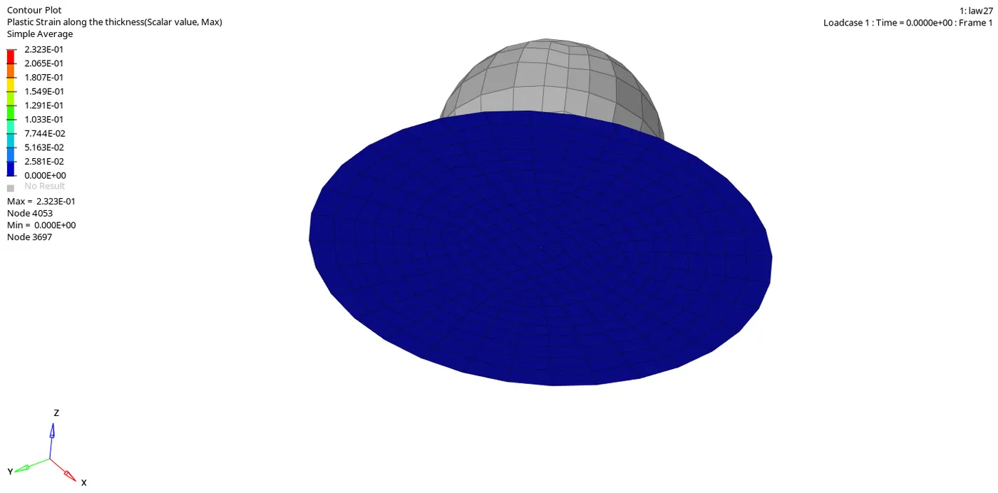
- The above animation represents the plastic stain on the plate, where the maximum value is 2.323E-01.
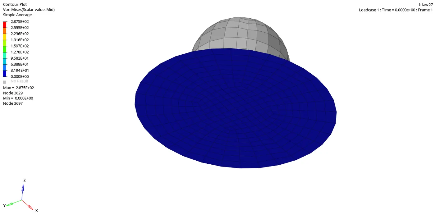
- The above animation represents the von mises stresses generated in the plate, and the maximum value is 2.875E+02.
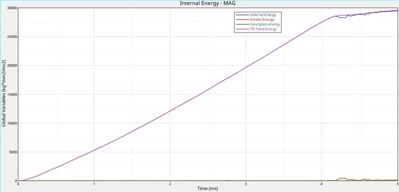
- The above plot shows the Total energy, Kinetic energy, Internal energy, and hourglass energy.
- The total energy is the summation of an internal, kinetic, hourglass, and contact energy.
- Internal energy is the sum of kinetic and potential energy in a system.
- The hourglass energy is controlled because of the element formulation.
Case 7: Law 36.
- The material card image is changed to M36_PLAS_TAB. The values are filled in the required columns to define the material card completely.
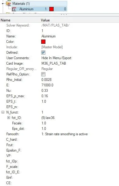
Fig 20: Material card definition.
- For the N_funct, a new curve is defined with the given values, and Fscale and Eps_dot are set to 1.
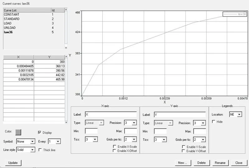
Fig 21: Plastic strains and their post-yield stress are plotted.
- The element formulation is taken according to the recommended values.
- Now we can proceed to run our simulation.
- Navigate to the analysis tab and choose the radioss option.
- Input file option will be available to save the starter and engine file in the desired location.
- In the options bar, "-nt 6" is entered, which denotes parallel processing for the simulation.
- Once all the options are selected correctly, click on the radioss button to run the simulation.
- A separate window pops up and shows the calculation going on, and it might take up to few seconds to minutes based on the complexity of the solution.
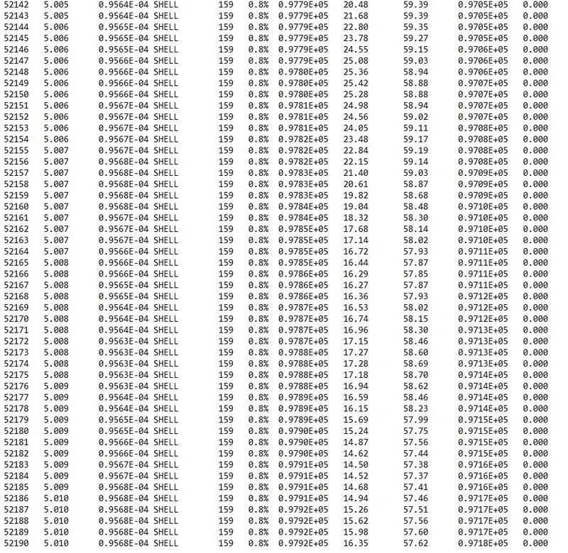
Fig 22: 0001.out files contains the solution information.
- We can check for the energy and mass error from the engine output file whether it lies within the permissible limit or not.
- The energy error starts from -0.3 to 0.8%, and the mass error is 0. Both are in the acceptable range, and we can proceed with the post-processing of our results.
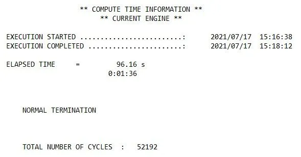
Fig 23: Compute time information.
- ELAPSED TIME = 96.16 s.
- TOTAL NUMBER OF CYCLES: 52192.
Results:
- For post-processing the results Hyperview and hypergraph are used.
- When hyperview is open, we need to load the model and results file of our simulation.
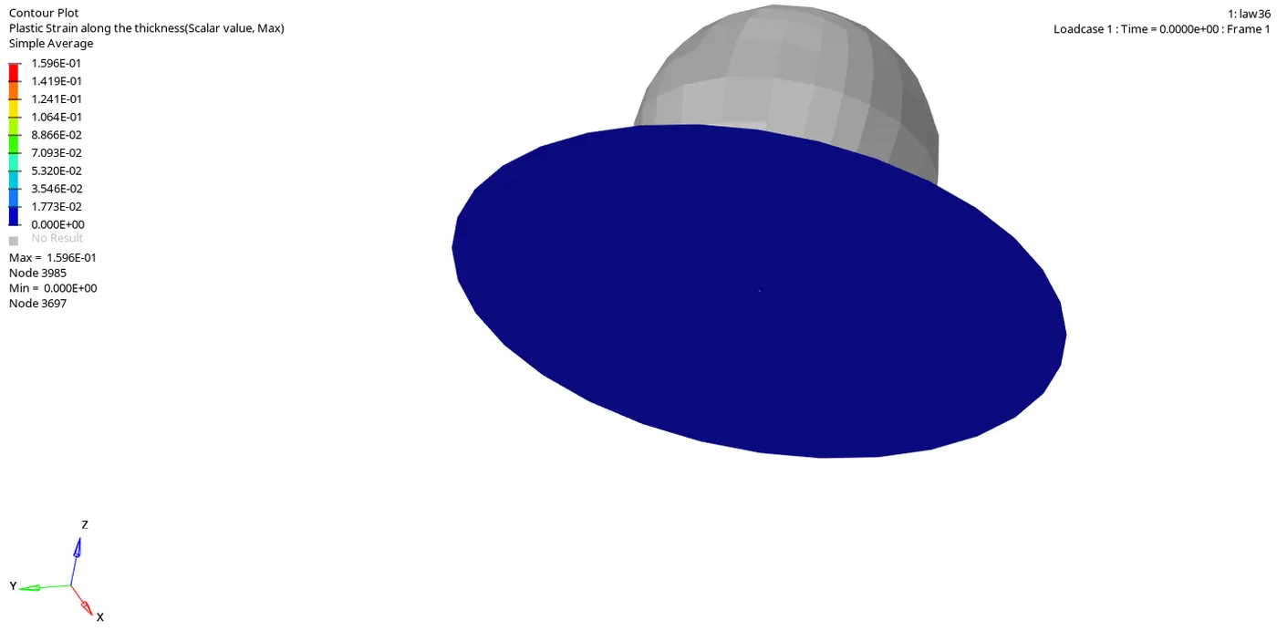
- The above animation represents the plastic stain on the plate, where the maximum value is 1.596E-01.
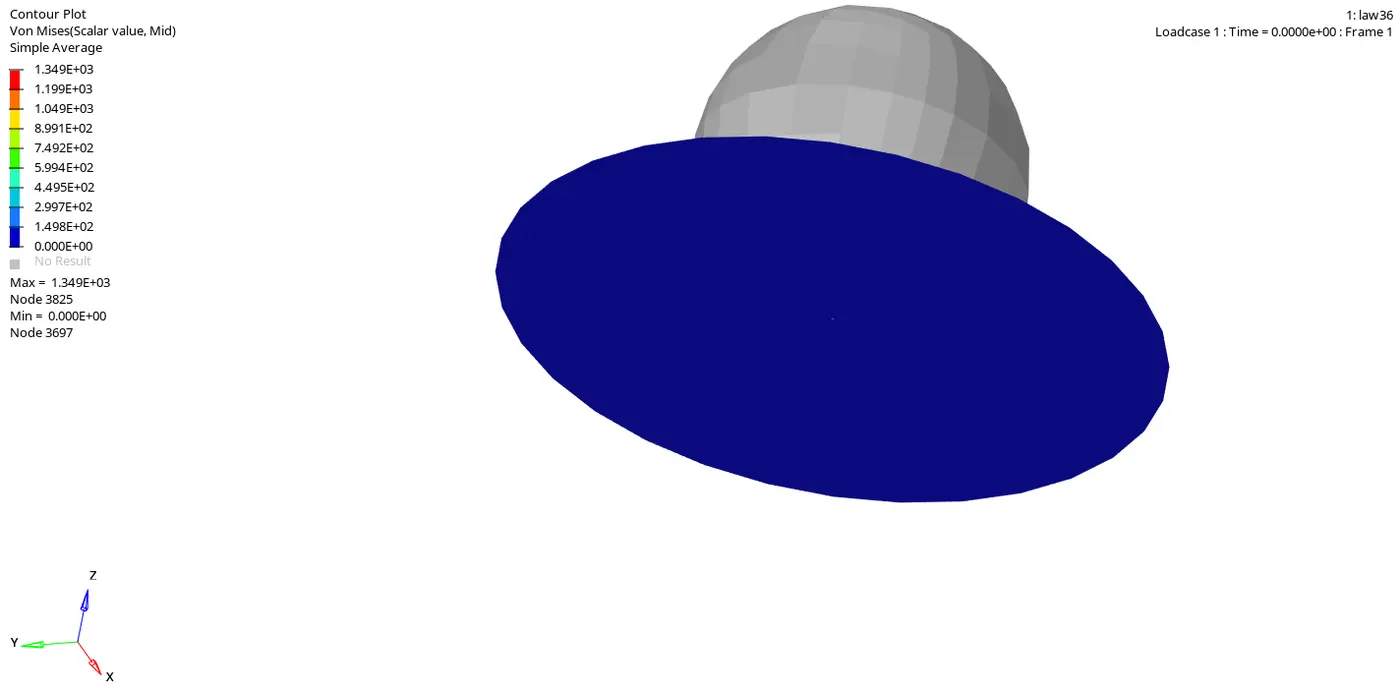
- The above animation represents the von mises stresses generated in the plate, and the maximum value is 1.349E+03.
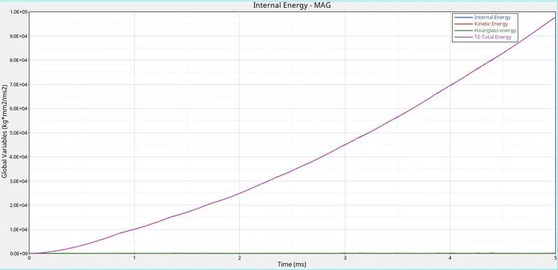
- The above plot shows the Total energy, Kinetic energy, Internal energy, and hourglass energy.
- The total energy is the summation of an internal, kinetic, hourglass, and contact energy.
- Internal energy is the sum of kinetic and potential energy in a system.
- The hourglass energy is controlled because of the element formulation.
Discussion of results for each case:
Case 1:
- In this case, law 2 is used, i.e., Johnson-Cook law.
- EPS_p_max of 0.151 is set, which means whenever the element crosses the yield stress and enters the plastic region, and the strain continues to increase, the loading is still occurring. When the value of stain is 15% of the maximum value, i.e., 425 MPa, the element is deleted, and the energy is dissipated.
- Here deletion of elements happens because there is no crack definition in the failure card. Only the D1, D2, and D3 parameters are defined, indicating the type of failure it is undergoing.
Case 2:
- In this case, law 2 is used, i.e., Johnson-Cook law.
- Ifail_sh, Dadv, and Ixfem options are set to 1, which means they are activated. Ixfem represents the crack formation in the elements, then the deleting of the elements happens. Dadv is the crack advancement.
- So the elements are first cracked, and then when it reaches the threshold value of EPS_p_max, they are deleted.
Case 3:
- In this case, law 2 is used, i.e., Johnson-Cook law.
- Here the failure card defining the element failure behavior is eliminated, leaving the material card itself. Here the type of failure modes are not present, and again as in case 1, the deletion of elements happens when the value of EPS_p_max is triggered.
Case 4:
- In this case, law 2 is used, i.e., Johnson-Cook law.
- The value of EPS_p_max is set to zero, i.e., there is no percent consideration of the plastic region.
- The failure of elements happens when the value of stress goes beyond the sigma max value defined in the card.
- We can see the maximum stress developed here is 4.247E+02; if it had run for one more millisecond, we could see the element deletion.
Case 5:
- In this case, law 1 is used, i.e., purely elastic.
- In this law, the plastic region consideration is absent entirely.
- As the stress increases, the strain also increases linearly. There is no failure region in this case.
- This material law is not suitable for models undergoing large deformations.
- It is evident from the Von Mises plot the maximum stress developed in the plate is 1.089E+04, and the plastic strain was 0.
Case 6:
- In this case, law 27 is used, i.e., brittle materials.
- As we know, brittle materials are strong, but their strain rate is significantly less. They can withstand large amounts of stress, and for that stress, the deformation is very minute. Once the stress reaches its ultimate point, failure happens.
- From the plastic strain plot, we can observe the maximum strain is 2.323E-01. The elements are deleted.
Case 7:
- In this case, law 36 is used, i.e., PLAS_TAB.
- The strain rates are user-defined in this law, where different conditions can be fitted into a curve and can be applied to the material.
- Once the EPS_p reaches the maximum EPS_p_max, the elements are deleted.
| Case | Material Law | Simulation Name | Simulation time (sec) | Number of cycles | Energy error % | Stress MPa | Element Failure Behaviour |
| 1 | Law 2 | law2_epsmax_failure | 78.69 | 49380 | 0.8 | 275.2 | deleted |
| 2 | Law 2 | law2_epsmax_crack | 110.79 | 49217 | 4.1 | 295.1 | cracks then deleted |
| 3 | Law 2 | law2_epsmax_nofail | 80.08 | 49408 | 0.8 | 270.7 | deleted |
| 4 | Law 2 | law2 | 83.17 | 48737 | 3 | 424.7 | preserved |
| 5 | Law 1 | law1 | 75.72 | 47969 | 1.3 | 1089 | preserved |
| 6 | Law 27 | law27 | 78.13 | 49508 | 0.8 | 287.5 | deleted |
| 7 | Law 36 | law36 | 96.16 | 52192 | 0.8 | 1349 | deleted |
Conclusion: Different material laws, i.e., 1, 2, 27, and 36, are studied with a rupture plate example, and the element failure behavior is noted down for each case. Among all the cases presented, case 2 (law 2) would best represent the on-field scenario. Also, law 36 would be an excellent material definition because different strain rates can be defined for the same material and according to the loading the appropriate curve is chosen by the solver and gives accurate results.