Assignment 4-RADIOSS Material Laws Challenge
Objective
Comparison of the 7 cases of the behaviour of the element with the changes in the material and element property. We compare the result when the do the changes in the failure card. We are gonna compare the total number of cycles, Energy error, mass error and simulation time, Hourglass energy, etc.
Introduction
Any good simulation depends on the input we have given in the simulation. So the simulation also depends on which type of material we are giving in the input and what are the properties we are giving to these materials. In the RADIOSS there are many types of material present. So we are going to change the material and their properties and we are going to use some different materials and we are going to analyse the effect of the changes.
(i). LAW1
LAW1 is an isotropic, Linear Elastic material using Hooke’s Law. It is available for truss, beam, shell and solid elements. It is used only for Elastic materials. To define the elasticity of the material we need to define three-point which are density, Young’s modulus and Poisson’s ratio.
(ii). LAW2
LAW2 is an isotropic elasto-plastic material. It uses the Johnson-Cook material model. This model expresses material stress as a function of strain, strain rate and temperature. We can decide at what plastic strain the element fails.
(iii). LAW36
LAW36 is an isotropic elasto-plastic material. This is more preferred in the industry. It gives a more accurate result. We can define the stress-strain curve in this material with different strain rate. It is available for brick and shell elements. The advantage of using this material is that we can add the Johnson-Cook failure model in this material.
(iv). LAW27
This law combines an isotropic elasto-plastic Johnson-Cook material model with an orthotropic brittle failure model. This is a special material card for brittle materials like Aluminium and glass etc. failure and damage is happening only in the tension. In this material the material damage is taken into account even before failure. It is used only for shell elements.
Procedure
Case-1
1. We are going to choose the profile to be Radioss.
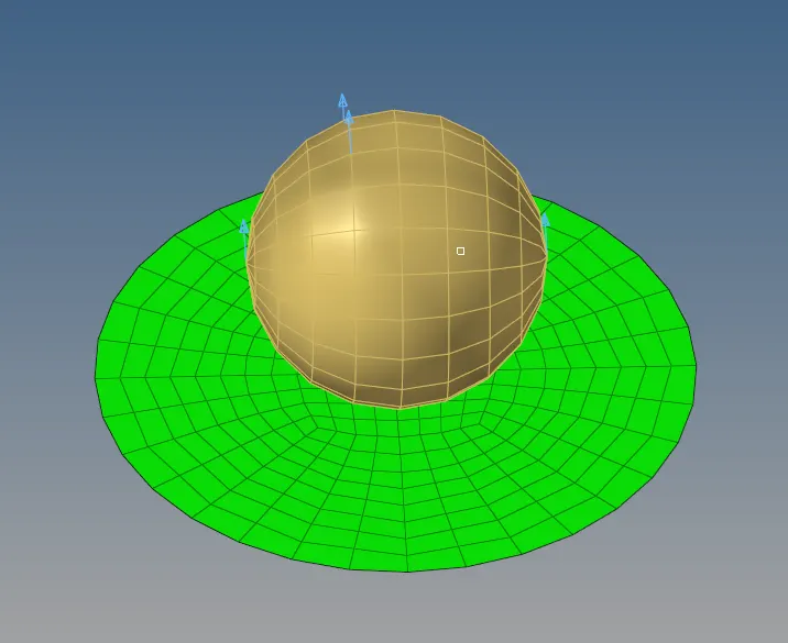
2. Now we are going to import the model.
3. Now we are going to check the unit of the model. For that, we will go to the BEGIN_CARD.
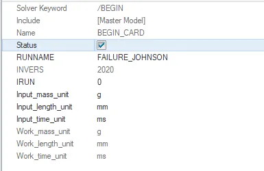
So the unit of the system is in g, mm, ms.
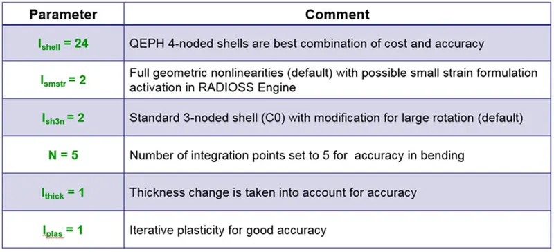
4. In this case we need to run the base Simulation. Before running this simulation, we need to change the Shell Elemental Properties to the recommended values. The following properties were used:
Ishell
When the thickness of the component is less than 6 mm we convert that component from 3D to 2D. So in that case we take the shell elements. So Ishell is the 2D representation of the 4 noded elements in the RADIOSS.
The recommended value of Ishell is Ishell =24. It is a QEPH type of element. Which is an improved under-integrated element. In this type of shell element, the integration point on the surfaces decreases. WHich decreases our computational time.
It uses the stiffness method which is a physical hourglass stabilization. So when the deformation goes beyond the limit. It increases the stiffness of the element. So that the simulation does not get unstable.
Ismstr
Ismstr is the small strain formulation. It goes activated when the element starts to deform. It stored the strain value of the elements.
The recommended value of the Ismstr is Ismstr = 2. When the elements get a large deformation/strain. It will switch to the large strain.
Ish3n
Ish3n is the representation of the 3 noded elements in the RADIOSS.
The recommended value of the Ish3n is Ish3n = 2. It is a standard triangle with modification for large rotation. It has only 1 integration point on the surface. There is hourglass deformation.
N
N is the no. of integration points we want through the thickness of the element. We can give the no. of integration points to be up to 10.
The recommended value of N is 5. When we take N to be 5 we get the accuracy with less cost.
Ithick
So when the elements start to deform, the thickness of the elements also changes. So we need to choose that if we want to take that change of the thickness into account or not.
The recommended value of the Ish3n is Ithick = 1. Which is that we have to take the change in the thickness to be in the account. Which gives us an accurate result.
Iplas
When the elements go beyond the elastic region and go to the plastic region it goes activated.
The recommended value of the Ish3n is Iplas = 1. When the elements go to the plastic region. It will calculate the values for the three iterations and give us the average value. It increases the simulation time but we will get the accurate result.
So in order to change the element property. We will go to the property
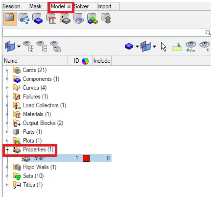
Here we will change the property to the recommended values.
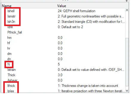
5. After changing the property we will run the simulation. To run the simulation we will go to the Analysis-->Radioss


In the radioss we are going to save the rad file into another folder with the name Law2_epsmax_failure and we are going to run the simulation.
6. To check the simulation we have done is correct or not we are going to check the energy error and mass error. If it is in the accepted range then we can say that our simulation is correct.
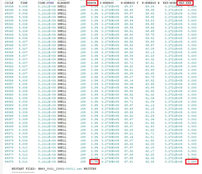
The energy error is between -15% to 5% and the mass error is 0. That is very less so we can see that the simulation we have done is right.
The total running time of the simulation was 99 seconds.
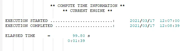
7. Now we have to analyze the simulation frame by frame and check the behaviour of the element after the impact.
Output
Simulation Gif
Displacement Gif
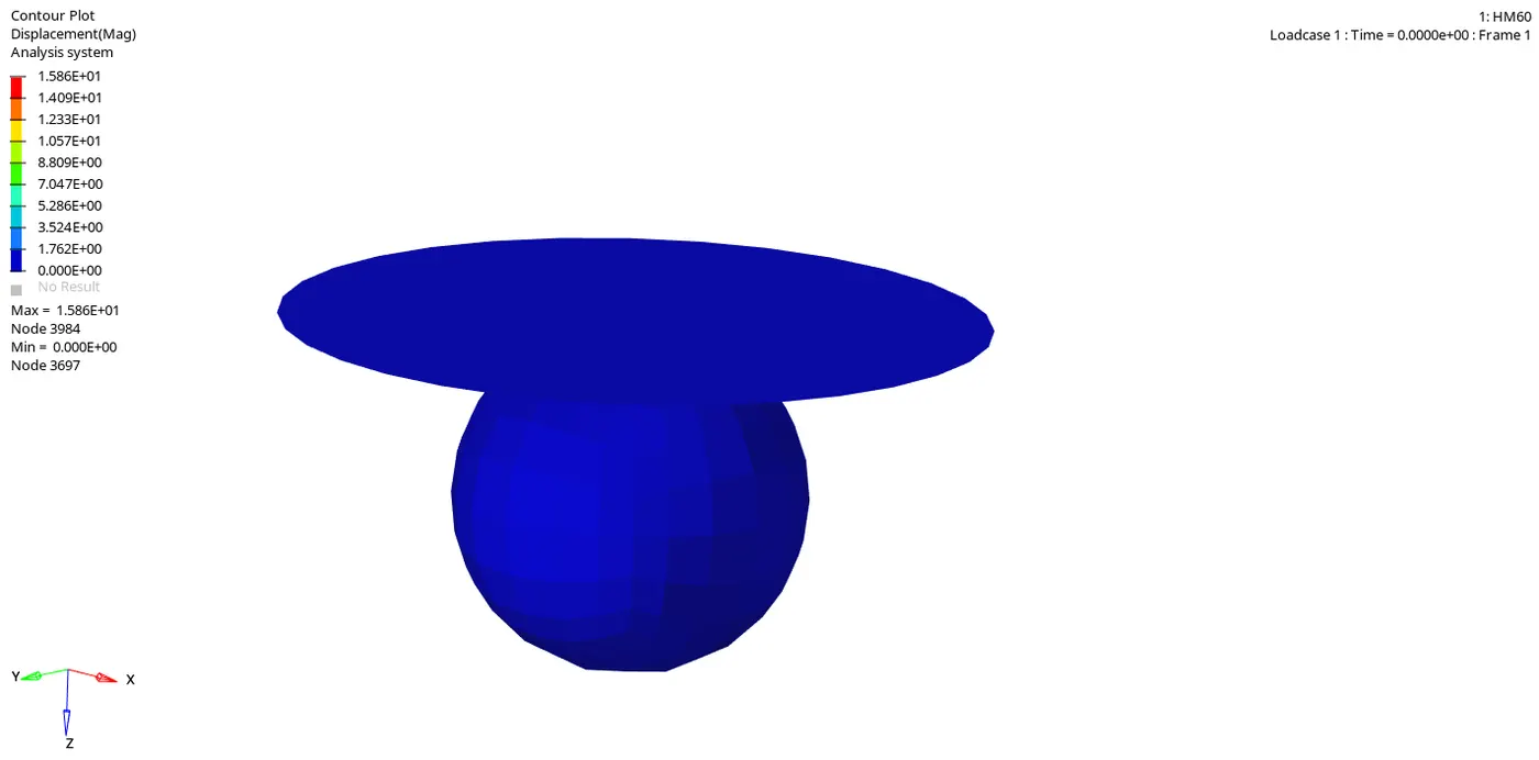
In this Gif, we can see that how many elements how much getting displaced.
Von Mises Gif
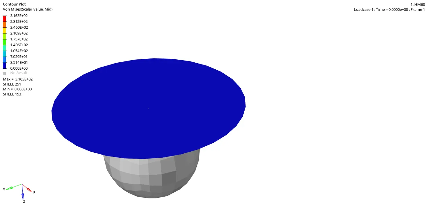
Von Mises stress is a value used to determine if a given material will yield or fracture. It is mostly used for ductile materials, such as metals. The von Mises yield criterion states that if the von Mises stress of a material under load is equal or greater than the yield limit of the same material under simple tension then the material will yield.
From both simulations, we can see that the elements which are getting deformed beyond the limit are getting detached from the component and flying away and deleted.
Energy Plots
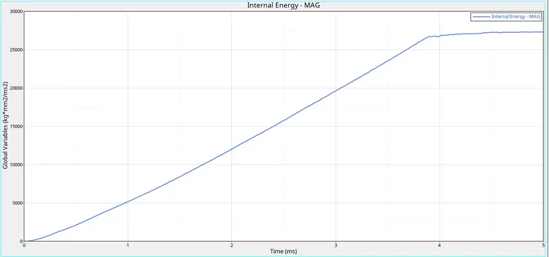
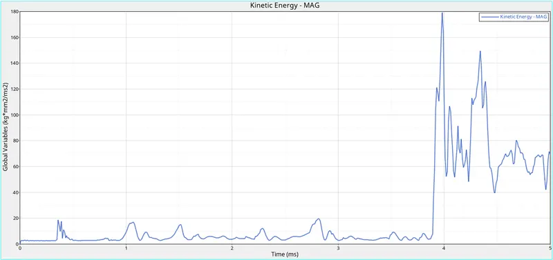
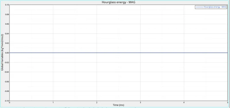
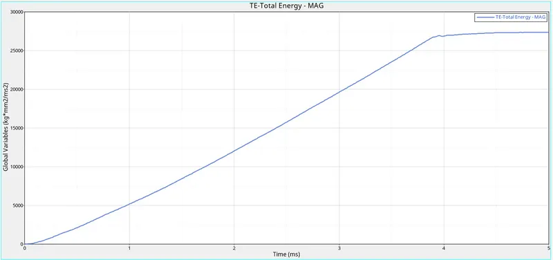
From the above graphs, we can see that the internal energy is increasing with respect to time but in the end, it remains constant.
The kinetic energy of the elements is zero in the beginning because the plate is stationary in this case and the rigid ball is moving. We get the sudden kinetic energy when the ball got an impact on the plate before that kinetic energy is very low that is because there is some movement in the plate caused by some disturbance and vibration. Kinetic energy is getting increase and decrease after the impact that's happening because of the contact between elements and rigid ball.
We have taken the shell element to be QEPH so we get hourglass energy to be zero.
In this case, the total energy is also increased with respect to time. Because it is the sum of kinetic energy and internal energy. So with the increase in the potential energy our total energy also get increases.
Rigid Wall Forces
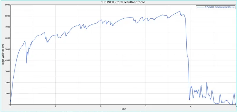
Rigid wall forces are the forces that are acting on the rigid wall by the other object.
In this case, the rigid wall is moving. So to move any object there should be some external force is applying to the object. So that is why the rigid wall forces start increasing to zero and when it collided with the plate, the energy got transferred to the elements, that's the reason the rigid wall forces get decrease.
Case-2
In this case, we have to do some changes to the failure card. To change these values, we need to click on the failure card and change the following given values.
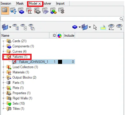
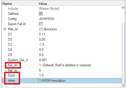
Ifail = 1 which determines the Shell element Failure method. So there are two ways in which we can see the element failing, the element will either get deleted or in some cases the cracking occurs according to the material properties.
Ixfem
In this, we can choose that if there is any element that is failing we want that element to delete or we want the element to be crack.
We are going to take Ixfem=1. Which allow failed element to cracked not to delete.
Dadv
It gets activated when we have taken Ixfem=1. We are going to take Dadv=1. Which gives the criteria that how much an element can get break into small pieces. If it goes beyond the limit the element gets delete.
After changing the property we will run the simulation. To run the simulation we will go to the Analysis-->Radioss

In the radioss we are going to save the rad file into another folder with the name Law2_epsmax_crack and we are going to run the simulation.
To check the simulation we have done is correct or not we are going to check the energy error and mass error. If it is in the accepted range then we can say that our simulation is correct.
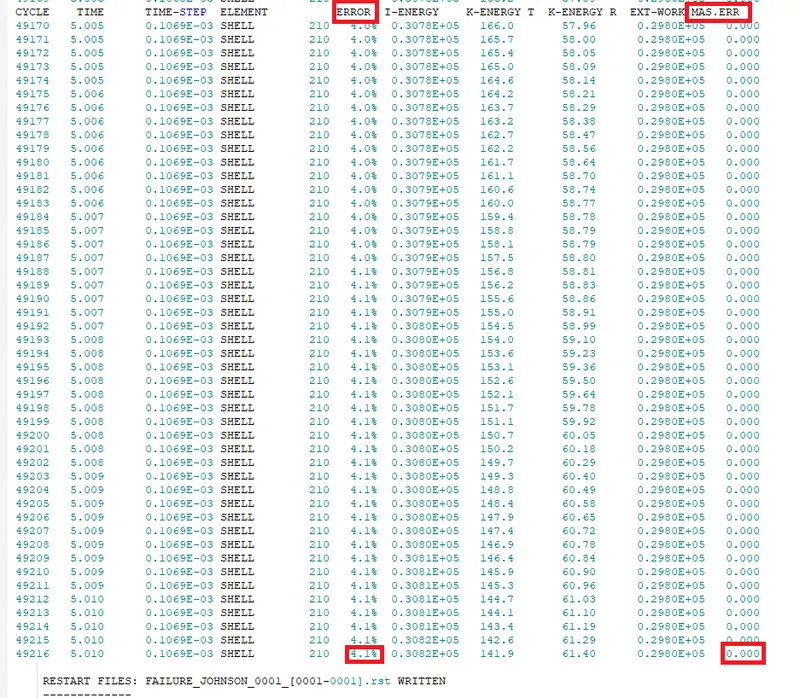
The energy error is between -15% to 5% and the mass error is 0. That is very less so we can see that the simulation we have done is right.
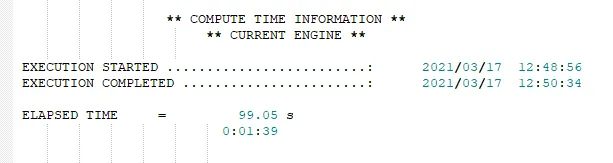
The total running time of the simulation was 99 seconds.
Now we have to analyze the simulation frame by frame and check the behaviour of the element after the impact.
Output
Simulation Gif
Displacement Gif
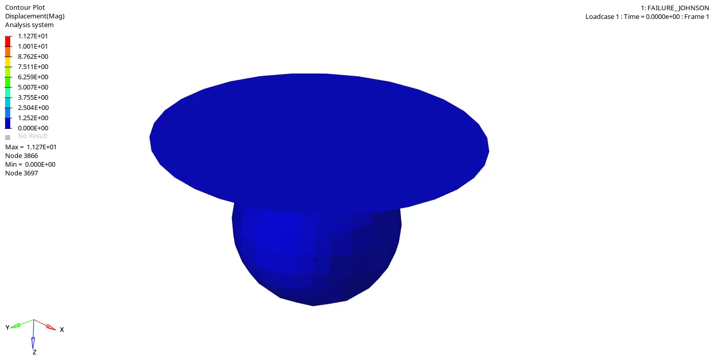
In this Gif, we can see that how many elements how much getting displaced.
Von Mises Gif
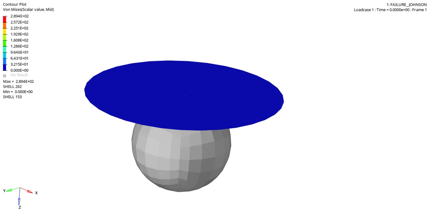
Von Mises stress is a value used to determine if a given material will yield or fracture. It is mostly used for ductile materials, such as metals. The von Mises yield criterion states that if the von Mises stress of a material under load is equal or greater than the yield limit of the same material under simple tension then the material will yield.
From both simulations, we can see that the elements are getting crack when they are failing. Elements are not flying away in this case. So when the elements break beyond the limit it gets deleted. But those elements are very few.
Energy Plots
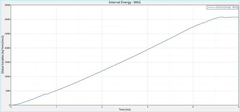
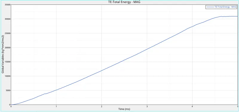
From the above graphs, we can see that the internal energy is increasing with respect to time but in the end, it remains constant.
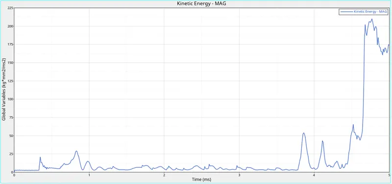
The kinetic energy of the elements is zero in the beginning because the plate is stationary in this case and the rigid ball is moving. We get the sudden kinetic energy when the ball got an impact on the plate before that kinetic energy is very low that is because there is some movement in the plate caused by some disturbance and vibration. The kinetic energy gets increase when the ball impacts the plate then it decreases and in the end, it goes very high. Kinetic energy is getting increase and decrease after the impact that's happening because of the contact between elements and rigid ball.
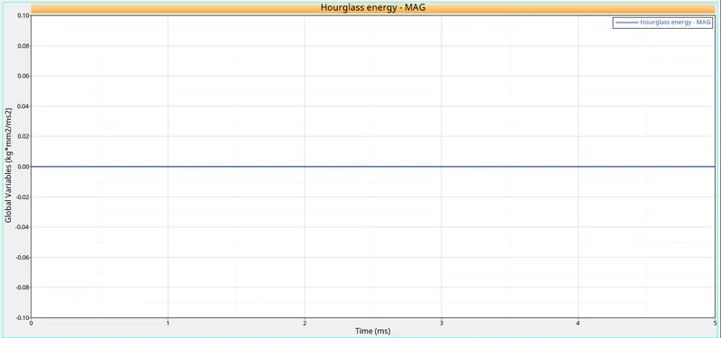
We have taken the shell element to be QEPH so we get hourglass energy to be zero.
In this case, the total energy is also increased with respect to time. Because it is the sum of kinetic energy, and internal energy. So with the increase in the potential energy our total energy also get increases.
Rigid Wall Forces
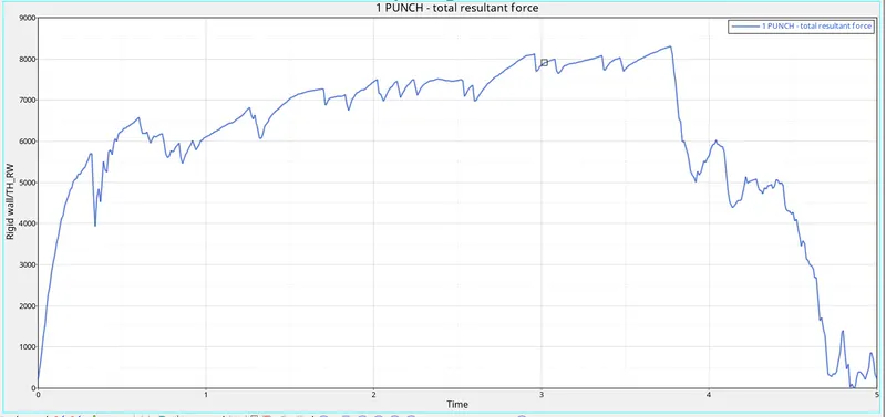
Rigid wall forces are the forces that are acting on the rigid wall by the other object.
In this case, the rigid wall is moving. So to move any object there should be some external force is applying to the object. So that is why the rigid wall forces start increasing to zero and when it collided with the plate, the energy got transferred to the elements, that's the reason the rigid wall forces get decrease.
Case-3
In this case, we are going to delete the Failure card and then run the simulation. To delete this card, we simply need to right-click on the failure card "Failure_JOHNSON_1" and then click on delete.
After deleting the failure card we will run the simulation. To run the simulation we will go to the Analysis-->Radioss

In the radioss we are going to save the rad file into another folder with the name Law2_epsmax_nofail and we are going to run the simulation.
To check the simulation we have done is correct or not we are going to check the energy error and mass error. If it is in the accepted range then we can say that our simulation is correct.
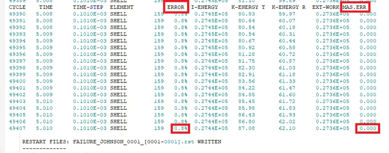
The energy error is between -15% to 5% and the mass error is 0. That is very less so we can see that the simulation we have done is right.
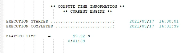
The total running time of the simulation was 99 seconds.
Now we have to analyze the simulation frame by frame and check the behaviour of the element after the impact.
Output
Simulation Gif
Displacement Gif
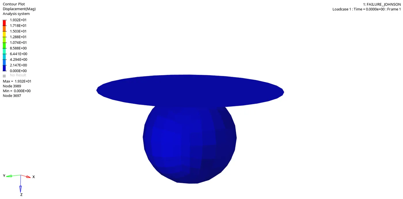
In this Gif, we can see that how many elements how much getting displaced.
Von Mises Gif
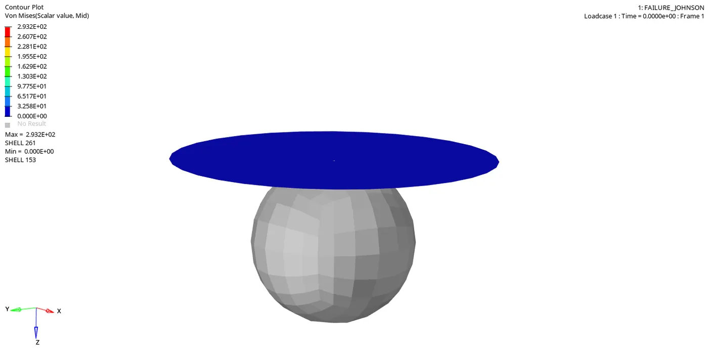
Von Mises stress is a value used to determine if a given material will yield or fracture. It is mostly used for ductile materials, such as metals. The von Mises yield criterion states that if the von Mises stress of a material under load is equal or greater than the yield limit of the same material under simple tension then the material will yield.
From both simulations, we can see that the elements which are getting deformed beyond the limit are getting detached from the component and flying away and deleted.
In this case, we have deleted Johnson failing card so we haven't defined any failing limit so the solver has taken the default values for the failure. So when it goes beyond those limitations, the element gets deleted.
Energy Plots
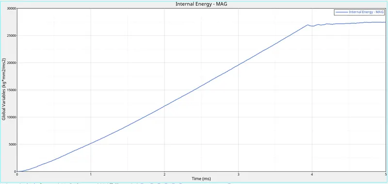
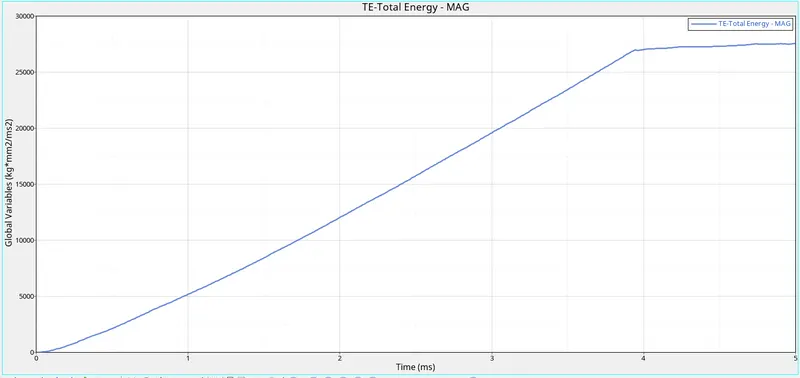
From the above graphs, we can see that the internal energy is increasing with respect to time but when they collide the internal energy gets constant.
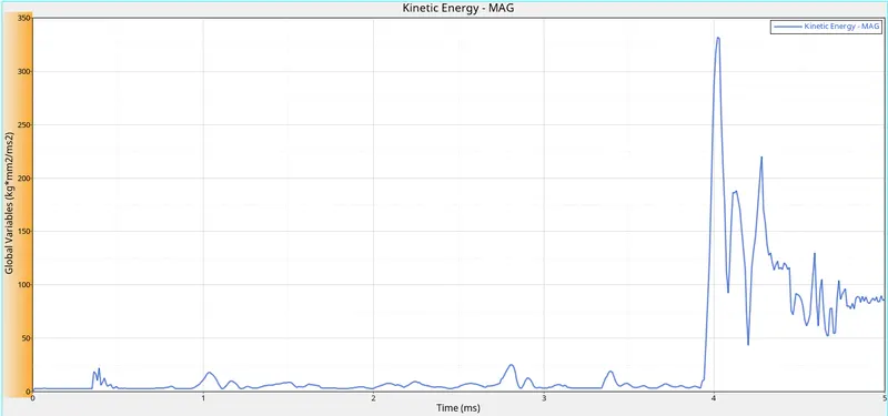
The kinetic energy of the elements is zero in the beginning because the plate is stationary in this case and the rigid ball is moving. We get the sudden kinetic energy when the ball got an impact on the plate before that kinetic energy is very low that is because there is some movement in the plate caused by some disturbance and vibration. After the sudden increase in the kinetic energy, it again gets decreases. Kinetic energy is getting increase and decrease after the impact that's happening because of the contact between elements and rigid ball.
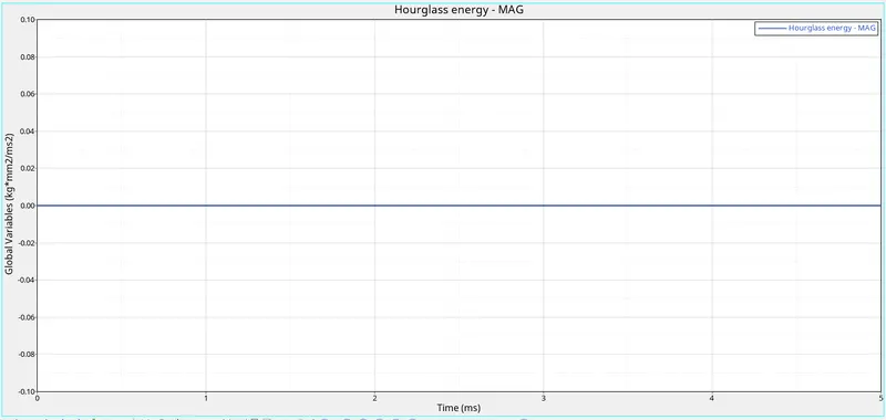
We have taken the shell element to be QEPH so we get hourglass energy to be zero.
In this case, the total energy is also increased with respect to time. Because it is the sum of kinetic energy, and internal energy. So with the increase in the potential energy our total energy also get increases.
Rigid Wall Forces
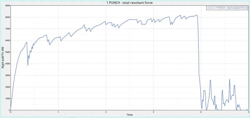
Rigid wall forces are the forces that are acting on the rigid wall by the other object.
In this case, the rigid wall is moving. So to move any object there should be some external force is applying to the object. So that is why the rigid wall forces start increasing to zero and when it collided with the plate, the energy got transferred to the elements, that's the reason the rigid wall forces get decrease.
Case-4
In this case, we need to set the value for EPS_p_max as zero and then run the simulation. This value of eps_p_max is called the Plastic strain for tension, compression or shear for the material. EPS_p value goes to the EPS_p_max value the elements gets deleted.
For changing the eps_max value we will go the material and we are going to change the value to be zero.
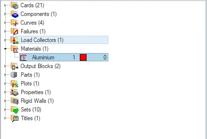
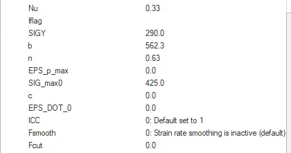
After changing the values we will run the simulation. To run the simulation we will go to the Analysis-->Radioss

In the radioss we are going to save the rad file into another folder with the name Law2 and we are going to run the simulation.
To check the simulation we have done is correct or not we are going to check the energy error and mass error. If it is in the accepted range then we can say that our simulation is correct.
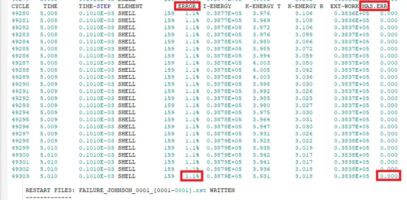
The energy error is between -15% to 5% and the mass error is 0. That is very less so we can see that the simulation we have done is right.
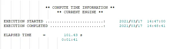
The total running time of the simulation was 101 seconds.
Now we have to analyze the simulation frame by frame and check the behaviour of the element after the impact.
Output
Simulation Gif
Displacement Gif
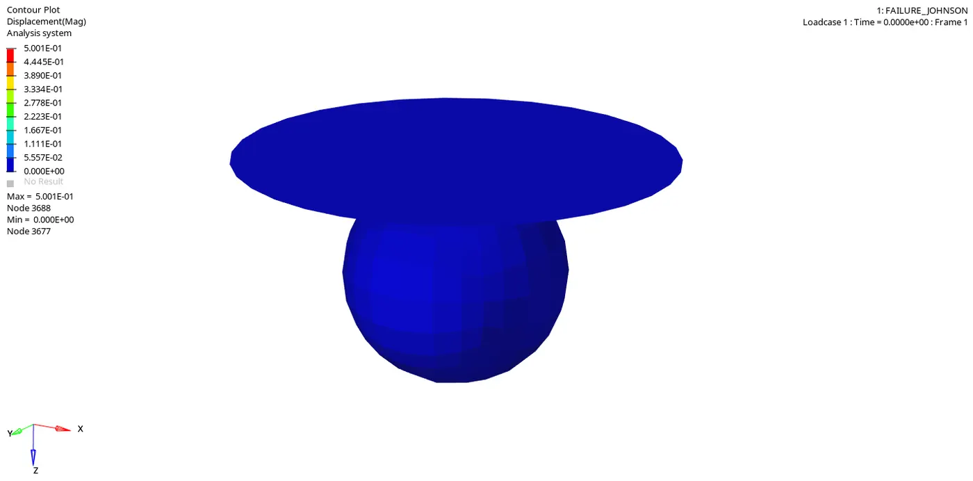
In this Gif, we can see that how many elements how much getting displaced.
Von Mises Gif
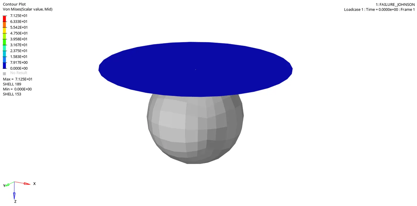
Von Mises stress is a value used to determine if a given material will yield or fracture. It is mostly used for ductile materials, such as metals. The von Mises yield criterion states that if the von Mises stress of a material under load is equal or greater than the yield limit of the same material under simple tension then the material will yield.
From both simulations, we can see that the elements are not failing because we have not given any EPS_p_max value. We have taken that as zero. So the element will not get deleted.
Energy Plots
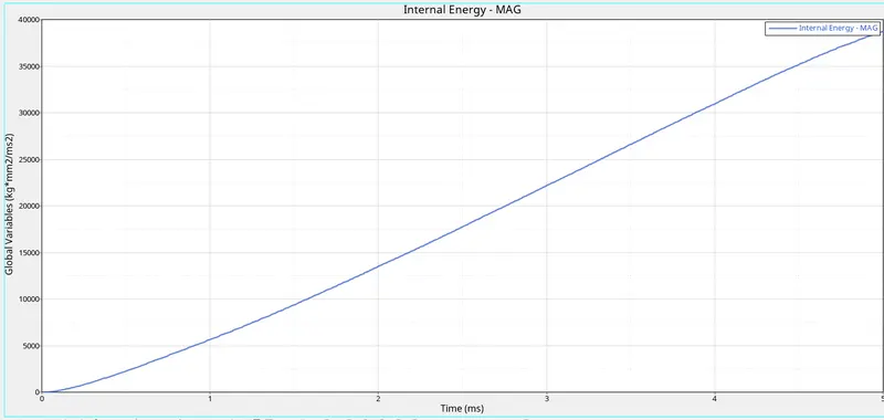
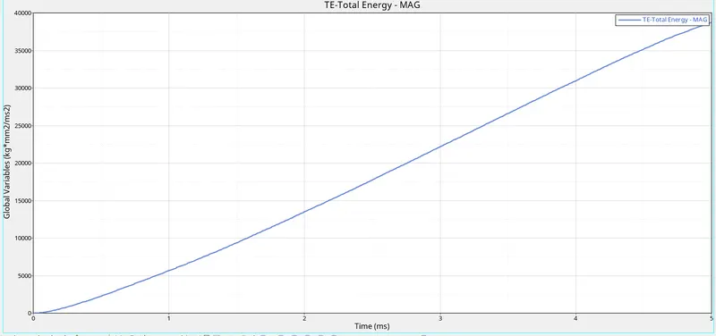
From the above graphs, we can see that the internal energy is increasing with respect to time.
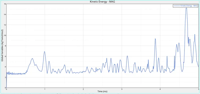
The kinetic energy of the elements is zero in the beginning because the plate is stationary in this case and the rigid ball is moving. We get the sudden kinetic energy when the ball got an impact on the plate before that kinetic energy is very low that is because there is some movement in the plate caused by some disturbance and vibration. After the sudden increase in the kinetic energy, it again gets decreases. Kinetic energy is getting increase and decrease after the impact that's happening because of the contact between elements and rigid ball.
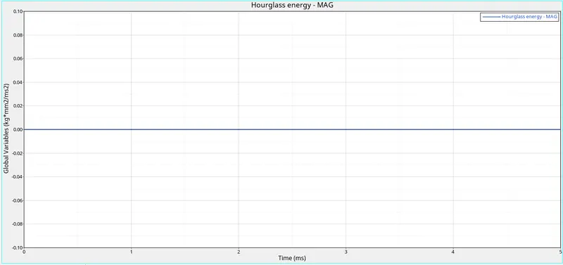
We have taken the shell element to be QEPH so we get hourglass energy to be zero.
In this case, the total energy is also increased with respect to time. Because it is the sum of kinetic energy, and internal energy. So with the increase in the potential energy our total energy also get increases.
Rigid Wall Forces
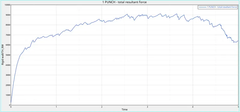
Rigid wall forces are the forces that are acting on the rigid wall by the other object.
In this case, the rigid wall is moving. So to move any object there should be some external force is applying to the object. So that is why the rigid wall forces start increasing to zero and when it collided with the plate, the energy got transferred to the elements, that's the reason the rigid wall forces get decrease.
Case-5
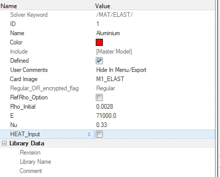
In this case, we are going to convert the model to Law1. We can use the same material values that we used in the earlier simulations.
To change the material we will go to the material card. There we will change the card image to be M1_ELAST and we are going to change the value of Young's modulus, density and Poisson's ratio.
After changing the values we will run the simulation. To run the simulation we will go to the Analysis-->Radioss

In the radioss we are going to save the rad file into another folder with the name Law1 and we are going to run the simulation.
To check the simulation we have done is correct or not we are going to check the energy error and mass error. If it is in the accepted range then we can say that our simulation is correct.
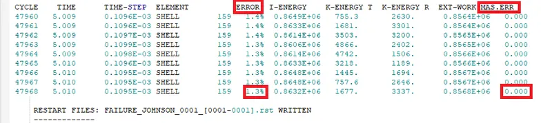
The energy error is between -15% to 5% and the mass error is 0. That is very less so we can see that the simulation we have done is right.
The total running time of the simulation was 96 seconds.
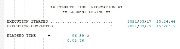
Now we have to analyze the simulation frame by frame and check the behaviour of the element after the impact.
Output
Simulation Gif
Displacement Gif
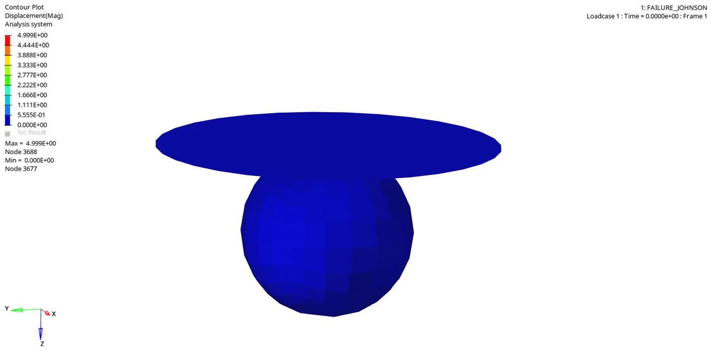
In this Gif, we can see that how many elements how much getting displaced.
Von Mises Gif
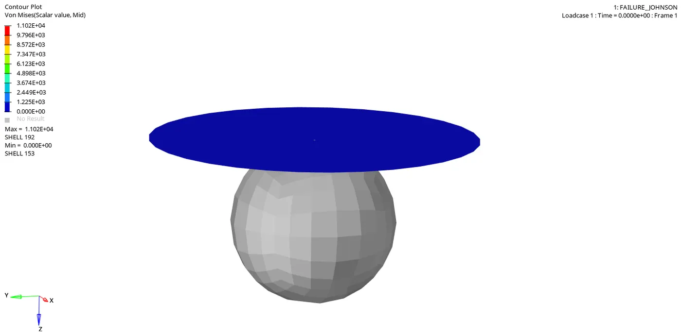
Von Mises stress is a value used to determine if a given material will yield or fracture. It is mostly used for ductile materials, such as metals. The von Mises yield criterion states that if the von Mises stress of a material under load is equal or greater than the yield limit of the same material under simple tension then the material will yield.
From both simulations, we can see that the elements are not breaking and deleting because we have taken LAW1 material which is an elastic material.
Energy Plots
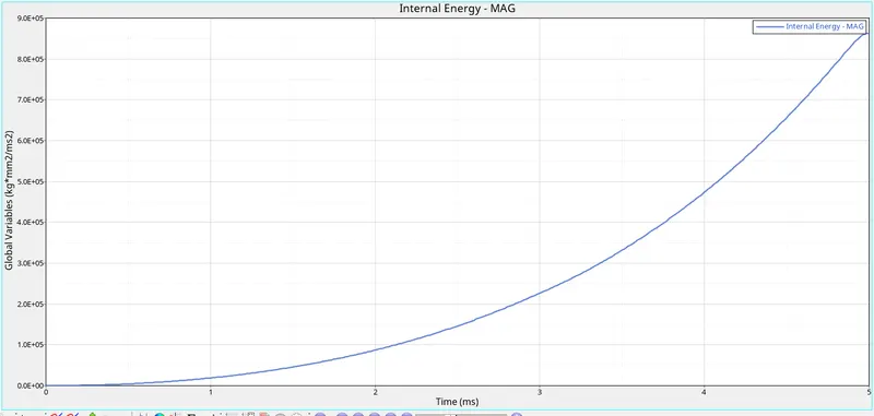
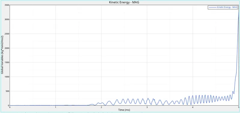
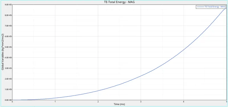
From the above graphs, we can see that the internal energy is increasing with respect to time.
The kinetic energy of the elements is zero in the beginning because the plate is stationary in this case and the rigid ball is moving. We get the sudden kinetic energy when the ball got an impact on the plate before that kinetic energy is very low that is because there is some movement in the plate caused by some disturbance and vibration. After the sudden increase in the kinetic energy, it again gets decreases. Kinetic energy is getting increase and decrease after the impact that's happening because of the contact between elements and rigid ball.
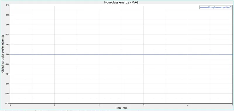
We have taken the shell element to be QEPH so we get hourglass energy to be zero.
In this case, the total energy is also increased with respect to time. Because it is the sum of kinetic energy, and internal energy. So with the increase in the potential energy our total energy also get increases.
Rigid Wall Forces
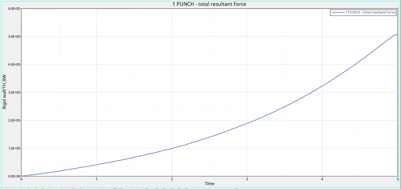
Rigid wall forces are the forces that are acting on the rigid wall by the other object.
In this case, the rigid wall is moving. So to move any object there should be some external force is applying to the object. So that is why the rigid wall forces start increasing to zero and when it collided with the plate, the energy is not decreasing. Because when they get impact elements are not breaking and they keep going attached to the rigid body. So the energy is transferring but it is not dissipating. That’s why the force keeps increasing.
Case-6
In this case, we need to convert the given model into Law36. Law 36 is elasto-plastic material. We need to define a curve in this case as well for the material properties to be applied.
To change the material we will go to the material card. There we will change the card image to be M36_PLAS_TAB.
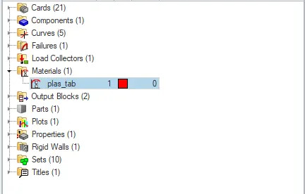
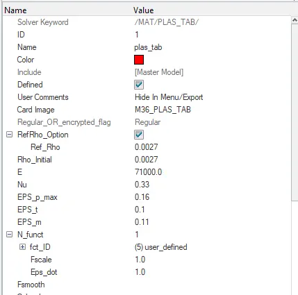
Now we are going to create the curve.
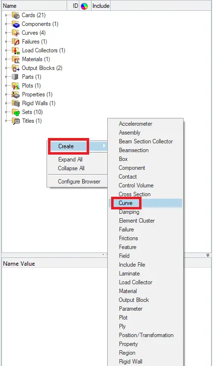
After this option was set, we then use the "New" option and set the name of the curve I have named the curve to be user-defined. Then we later give in the values that are to be fed so that we get a proper curve.
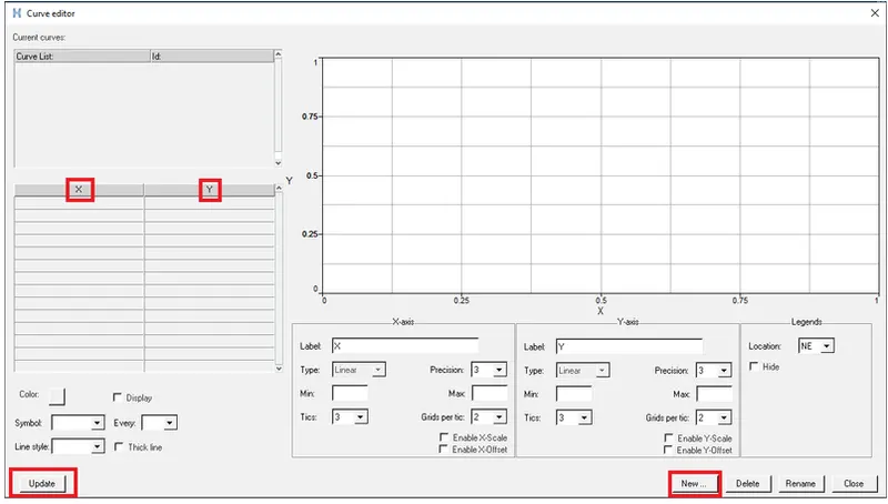
The following value we will give in the curve:
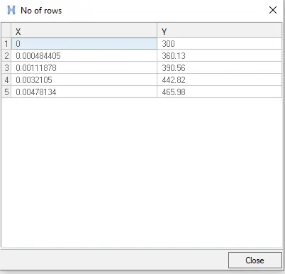
Now, this curve we are going to define in the material card in the function option. In which we are going to give the no. of function to be 1.
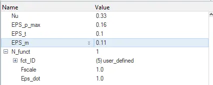
After changing the values we will run the simulation. To run the simulation we will go to the Analysis-->Radioss

In the radioss we are going to save the rad file into another folder with the name Law36 and we are going to run the simulation.
To check the simulation we have done is correct or not we are going to check the energy error and mass error. If it is in the accepted range then we can say that our simulation is correct.
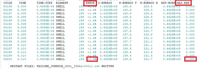
The energy error is between -15% to 5% and the mass error is 0. That is very less so we can see that the simulation we have done is right.
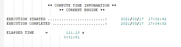
The total running time of the simulation was 111 seconds.
Now we have to analyze the simulation frame by frame and check the behaviour of the element after the impact.
Output
Simulation Gif
Displacement Gif
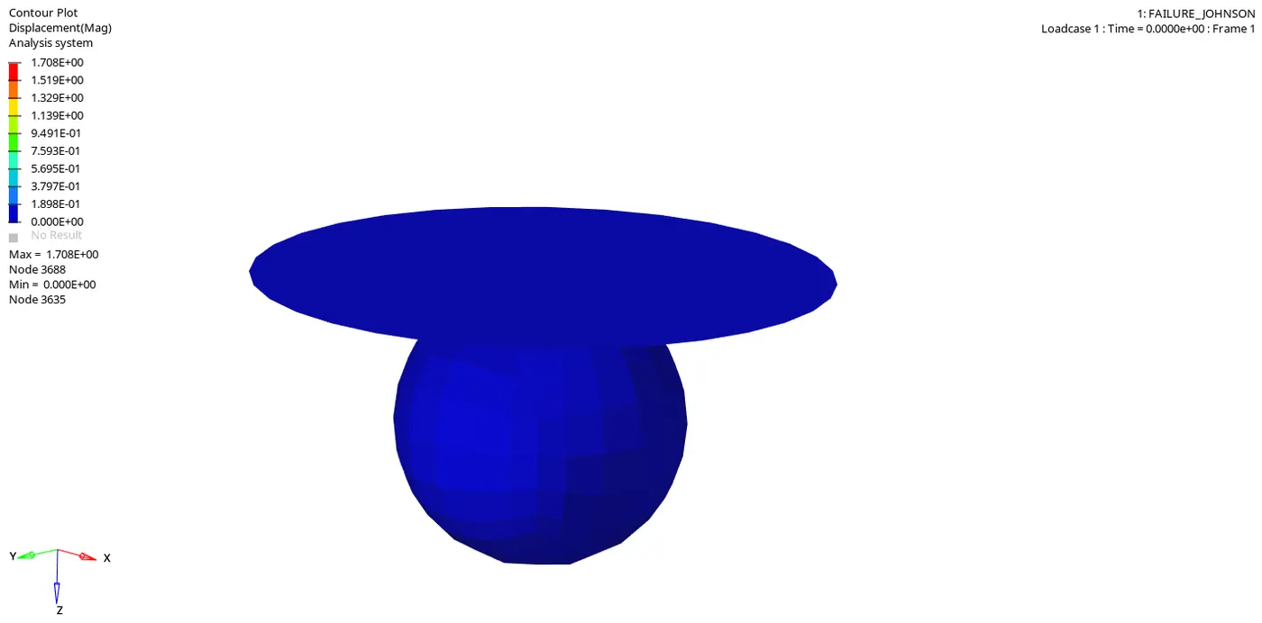
In this Gif, we can see that how many elements how much getting displaced.
Von Mises Gif
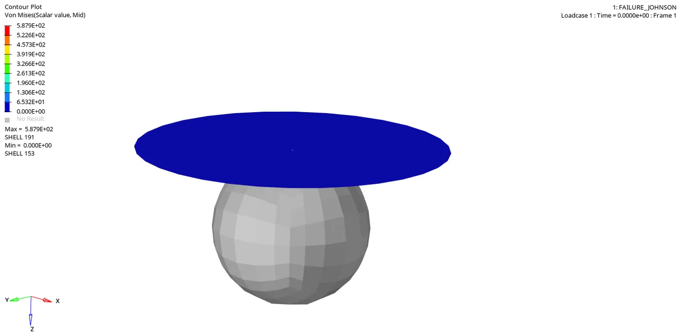
Von Mises stress is a value used to determine if a given material will yield or fracture. It is mostly used for ductile materials, such as metals. The von Mises yield criterion states that if the von Mises stress of a material under load is equal or greater than the yield limit of the same material under simple tension then the material will yield.
From both simulations, we can see that the elements failing after the impact. They are flying away and then some elements get deleted..
Energy Plots
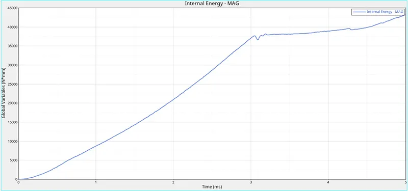
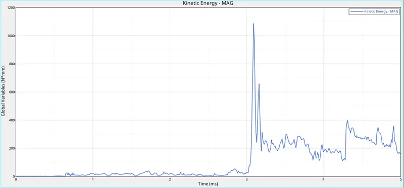
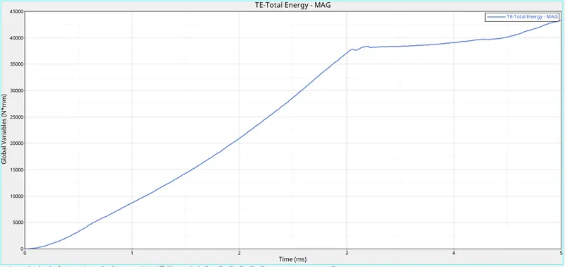
From the above graphs, we can see that the internal energy is increasing with respect to time In the end the rate of increase of the energy get decreases.
The kinetic energy of the elements is zero in the beginning because the plate is stationary in this case and the rigid ball is moving. We get the sudden kinetic energy when the ball got an impact on the plate before that kinetic energy is very low that is because there is some movement in the plate caused by some disturbance and vibration. After the sudden increase in the kinetic energy, it again gets decreases. Kinetic energy is getting increase and decrease after the impact that's happening because of the contact between elements and rigid ball.
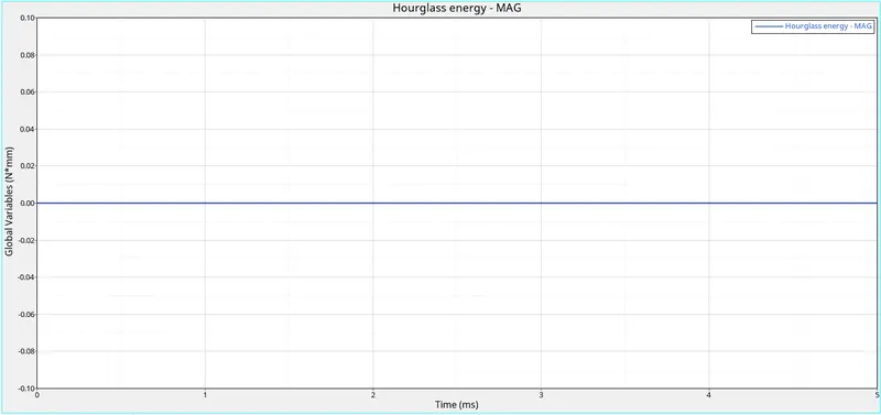
We have taken the shell element to be QEPH so we get hourglass energy to be zero.
In this case, the total energy is also increased with respect to time. Because it is the sum of kinetic energy, and internal energy. So with the increase in the potential energy our total energy also get increases.
Rigid Wall Forces
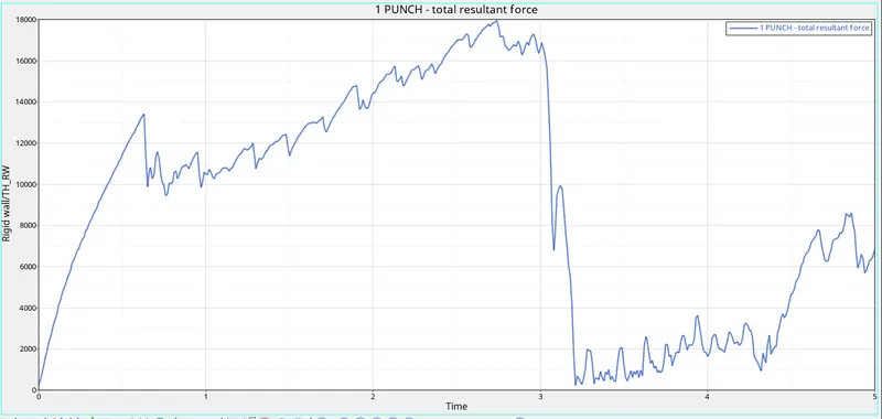
Rigid wall forces are the forces that are acting on the rigid wall by the other object.
In this case, the rigid wall is moving. So to move any object there should be some external force is applying to the object. So that is why the rigid wall forces start increasing to zero and when it collided with the plate, the energy got transferred to the elements, that's the reason the rigid wall forces get decrease.
Case-7
In this case, we need to convert the given model into Law27. Law 27 is Elasto-plastic brittle material.
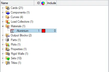
To change the material we will go to the material card. There we will change the card image to be M27_PLAS_BRIT.
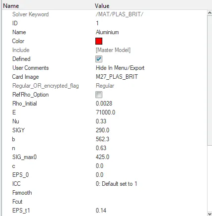
After changing the values we will run the simulation. To run the simulation we will go to the Analysis-->Radioss

In the radioss we are going to save the rad file into another folder with the name Law27 and we are going to run the simulation.
To check the simulation we have done is correct or not we are going to check the energy error and mass error. If it is in the accepted range then we can say that our simulation is correct.
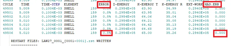
The energy error is between -15% to 5% and the mass error is 0. That is very less so we can see that the simulation we have done is right.
The total running time of the simulation was 99 seconds.
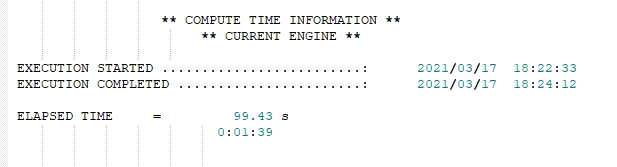
Now we have to analyze the simulation frame by frame and check the behaviour of the element after the impact.
Output
Simulation Gif
Displacement Gif
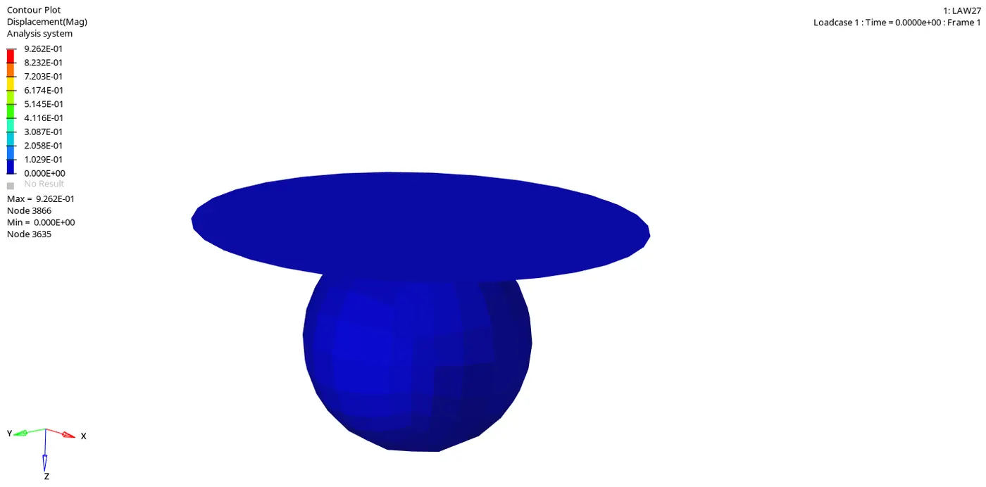
In this Gif, we can see that how many elements how much getting displaced.
Von Mises Gif
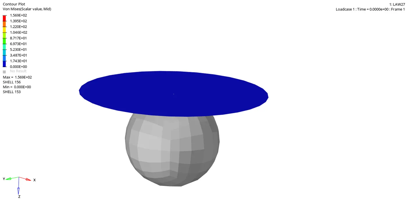
Von Mises stress is a value used to determine if a given material will yield or fracture. It is mostly used for ductile materials, such as metals. The von Mises yield criterion states that if the von Mises stress of a material under load is equal or greater than the yield limit of the same material under simple tension then the material will yield.
From both simulations, we can see that the elements failing after the impact. They are flying away and then some elements get deleted.
Energy Plots
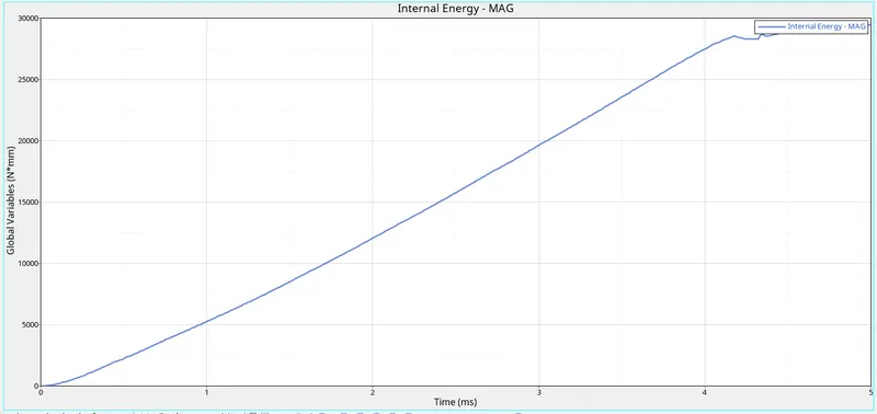
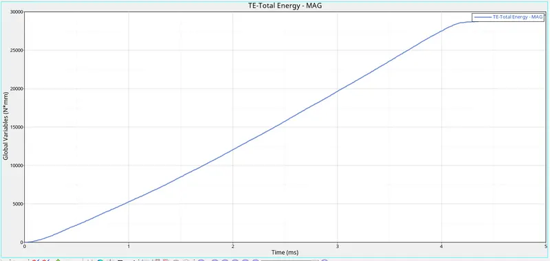
From the above graphs, we can see that the internal energy is increasing with respect to time but when they collide the internal energy gets almost constant.
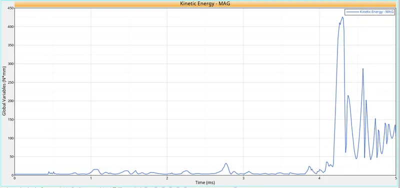
The kinetic energy of the elements is zero in the beginning because the plate is stationary in this case and the rigid ball is moving. We get the sudden kinetic energy when the ball got an impact on the plate before that kinetic energy is very low that is because there is some movement in the plate caused by some disturbance and vibration. After the sudden increase in the kinetic energy, it again gets decreases. Kinetic energy is getting increase and decrease after the impact that's happening because of the contact between elements and rigid ball.
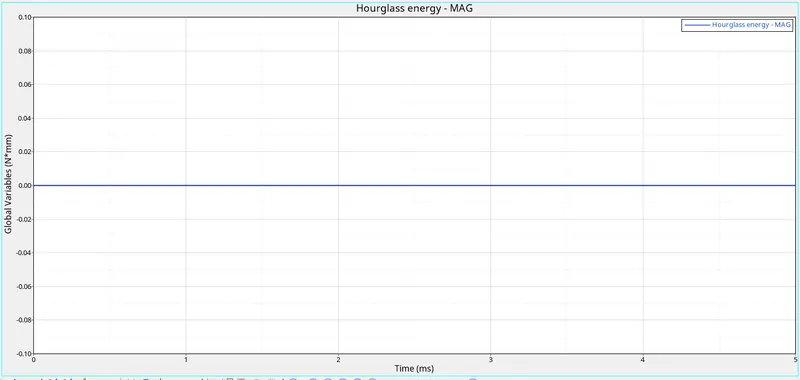
We have taken the shell element to be QEPH so we get hourglass energy to be zero.
In this case, the total energy is also increased with respect to time. Because it is the sum of kinetic energy, and internal energy. So with the increase in the potential energy our total energy also get increases.
Rigid Wall Forces
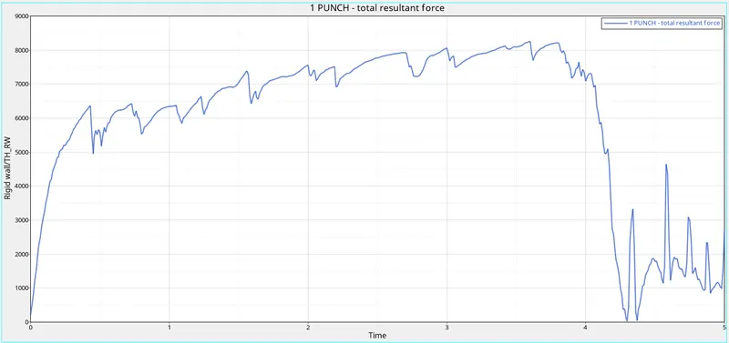
Rigid wall forces are the forces that are acting on the rigid wall by the other object.
In this case, the rigid wall is moving. So to move any object there should be some external force is applying to the object. So that is why the rigid wall forces start increasing to zero and when it collided with the plate, the energy got transferred to the elements, that's the reason the rigid wall forces get decrease.
Comparison
Now we are going to compare all 7 cases.
| Case | No. of cycles | Energy error | Mass error | Simulation time | Elements after impact |
| case-1 | 49379 | 0.8 | 0.0 | 99 | Deleting after deforming beyond the limit |
| case-2 | 49216 | 4.1 | 0.0 | 99 | Deleting after deforming beyond the limit |
| case-3 | 49407 | 0.8 | 0.0 | 99 | Deleting after deforming beyond the limit |
| case-4 | 49303 | 1.1 | 0.0 | 101 | Deforming but not deleting |
| case-5 | 47968 | 1.3 | 0.0 | 96 | Stretching |
| case-6 | 53200 | -1.4 | 0.0 | 111 | Deleting after deforming beyond the limit |
| case-7 | 49506 | 0.8 | 0.0 | 99 | Deleting after failing |
Learning Outcome:-
Learn about different type of material cards.
Learn what effects occurs with the change in the material in the outcome of the simulation.
Learn about the failue card in hypermesh.
Learn about contact energy, hourglass energy.
Learn about rigid wall forces.
Learn how to create the graphs and save Gif files in the HyperWork.